日本語
日本語 English
 Deutsch
 中文
中文 한국어
한국어


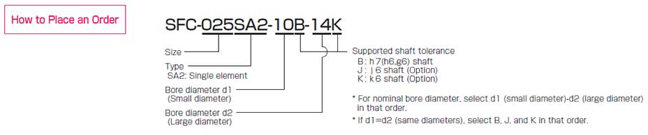
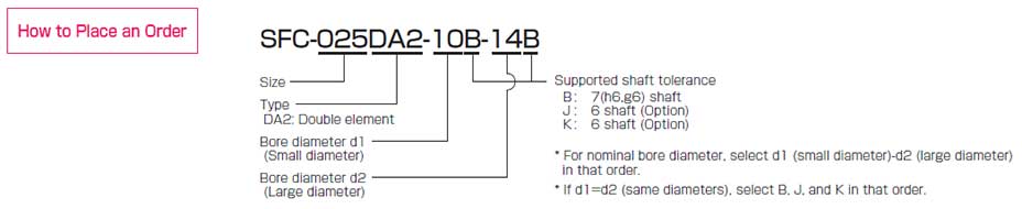
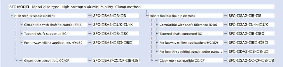
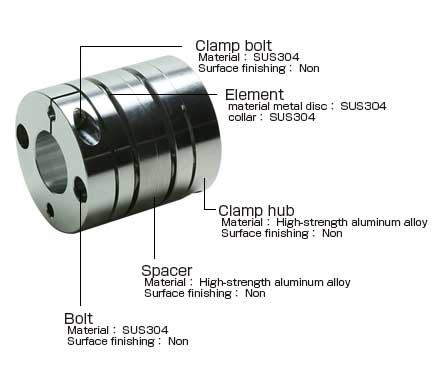
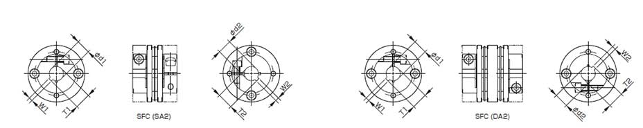
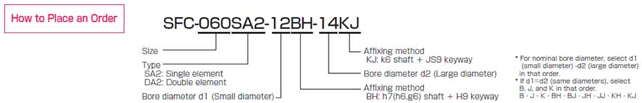
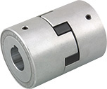
SFC Models

![]()
SFC-□SA2(BC)
[Specifications]
| Model | shape TYPE | Rated torque [N・m] |
Misalignment | Max. rotation speed [min-1] |
Torsional stiffness [N・m/rad] |
Axial stiffness [N/mm] |
Moment of inertia [kg・m2] |
Mass [kg] |
||
|---|---|---|---|---|---|---|---|---|---|---|
| Parallel [mm] |
Angular [°] |
Axial [mm] |
||||||||
| SFC-040SA2-□B-11BC | B | 12 | 0.02 | 1 | ±0.3 | 10000 | 20000 | 80 | 26.58×10⁻⁶ | 0.131 |
| C | 12 | 0.02 | 1 | ±0.3 | 10000 | 20000 | 80 | 33.28×10⁻⁶ | 0.146 | |
| SFC-050SA2-□B-11BC | B | 25 | 0.02 | 1 | ±0.4 | 10000 | 32000 | 48 | 82.91×10⁻⁶ | 0.240 |
| C | 25 | 0.02 | 1 | ±0.4 | 10000 | 32000 | 48 | 103.5×10⁻⁶ | 0.258 | |
| SFC-050SA2-□B-14BC | B | 25 | 0.02 | 1 | ±0.4 | 10000 | 32000 | 48 | 88.72×10⁻⁶ | 0.271 |
| C | 25 | 0.02 | 1 | ±0.4 | 10000 | 32000 | 48 | 111.5×10⁻⁶ | 0.301 | |
| SFC-050SA2-□B-16BC | B | 25 | 0.02 | 1 | ±0.4 | 10000 | 32000 | 48 | 95.44×10⁻⁶ | 0.309 |
| C | 25 | 0.02 | 1 | ±0.4 | 10000 | 32000 | 48 | 118.2×10⁻⁶ | 0.338 | |
| SFC-055SA2-□B-14BC | C | 40 | 0.02 | 1 | ±0.42 | 10000 | 50000 | 43 | 201.1×10⁻⁶ | 0.409 |
| SFC-055SA2-□B-16BC | C | 40 | 0.02 | 1 | ±0.42 | 10000 | 50000 | 43 | 207.8×10⁻⁶ | 0.446 |
| SFC-060SA2-□B-16BC | B | 60 | 0.02 | 1 | ±0.45 | 10000 | 70000 | 76.4 | 228.7×10⁻⁶ | 0.475 |
| C | 60 | 0.02 | 1 | ±0.45 | 10000 | 70000 | 76.4 | 287.8×10⁻⁶ | 0.517 | |
* Types B / C are automatically specified by Miki Pulley according to the bore diameter you select, and cannot be specified by the customer.
* Check the "Standard Bore Diameters" as rated torque may be restricted by the holding power of the shaft connection component.
* Max. rotation speed does not take into account dynamic balance.
* Torsional stiffness values given are measured values for the element alone.
* The moment of inertia and mass are measured for the maximum bore diameter.
[Dimensions]

| Model | d2 | W | T | WA | LA | dA | DA | LL | D | L | LF | C | A1 | A2 | M Qty - Nominal dia. |
|---|---|---|---|---|---|---|---|---|---|---|---|---|---|---|---|
| SFC-040SA2-□B-11BC | 11 | 4 | 12.2 | 18 | 16 | 17 | 22 | 44 | 44 | 34 | 15.5 | 4.5 | 11 | 17 | 1-M4 |
| SFC-050SA2-□B-11BC | 11 | 4 | 12.2 | 18 | 16 | 17 | 22 | 48.4 | 56 | 43.4 | 20.5 | 6 | 14.5 | 22 | 1-M5 |
| SFC-050SA2-□B-14BC | 14 | 4 | 15.1 | 24 | 19 | 22 | 28 | 53.4 | 56 | 43.4 | 20.5 | 6 | 14.5 | 22 | 1-M5 |
| SFC-050SA2-□B-16BC | 16 | 5 | 17.3 | 24 | 29 | 26 | 30 | 63.4 | 56 | 43.4 | 20.5 | 6 | 14.5 | 22 | 1-M5 |
| SFC-055SA2-□B-14BC | 14 | 4 | 15.1 | 24 | 19 | 22 | 28 | 56.6 | 63 | 50.6 | 24 | 7.75 | - | 23 | 1-M6 |
| SFC-055SA2-□B-16BC | 16 | 5 | 17.3 | 24 | 29 | 26 | 30 | 66.6 | 63 | 50.6 | 24 | 7.75 | - | 23 | 1-M6 |
| SFC-060SA2-□B-16BC | 16 | 5 | 17.3 | 24 | 29 | 26 | 30 | 69.6 | 68 | 53.6 | 25.2 | 7.75 | 17.5 | 26.5 | 1-M6 |
* For other dimensions, see dimensions for single element type SFC-□SA2.
[Standard bore diameter]
| Standard (option) bore diameter, d1 [mm] and restricted rated torque [N・m] | ||||||||||||||||||||||
|---|---|---|---|---|---|---|---|---|---|---|---|---|---|---|---|---|---|---|---|---|---|---|
| Nominal bore diameter | 8 | 9 | 9.525 | 10 | 11 | 12 | 13 | 14 | 15 | 16 | 17 | 18 | 19 | 20 | 22 | 24 | 25 | 28 | 30 | 32 | 35 | |
| Shaft tolerance h7(h6,g6) | B | ● | ● | ● | ● | ● | ● | ● | ● | ● | ● | ● | ● | ● | ● | ● | ● | ● | ● | ● | ● | ● |
| Shaft tolerance j6(option) | J | ○ | ○ | ○ | ○ | |||||||||||||||||
| Shaft tolerance k6(option) | K | ○ | ○ | ○ | ○ | ○ | ○ | ○ | ○ | |||||||||||||
| SFC-040SA2-□B-11BC | 9 | ● | ● | ● | ● | ● | ● | ● | ● | ● | ● | ● | ● | |||||||||
| SFC-050SA2-□B-11BC | 18 | 20 | 22 | 22 | ● | ● | ● | ● | ● | ● | ● | ● | ● | ● | ● | ● | ● | ● | ● | |||
| SFC-050SA2-□B-14BC | 18 | 20 | 22 | 22 | ● | ● | ● | ● | ● | ● | ● | ● | ● | ● | ● | ● | ● | |||||
| SFC-050SA2-□B-16BC | 18 | 20 | 22 | 22 | ● | ● | ● | ● | ● | ● | ● | ● | ● | ● | ● | ● | ● | |||||
| SFC-055SA2-□B-14BC | 31 | 34 | 36 | 38 | ● | ● | ● | ● | ● | ● | ● | ● | ● | ● | ● | ● | ||||||
| SFC-055SA2-□B-16BC | 31 | 34 | 36 | 38 | ● | ● | ● | ● | ● | ● | ● | ● | ● | ● | ● | ● | ||||||
| SFC-060SA2-□B-16BC | 50 | 51 | ● | ● | ● | ● | ● | ● | ● | ● | ● | ● | ● | ● | ● | ● | ● | |||||
* The shaft tolerance for standard bore diameter is h7 (h6 or g6): designation B. However, for a bore diameter of ø35, the shaft tolerance is -0.025 to +0.010.
* Shaft tolerances j6/k6: designations J/K are optional, and are only supported for bore diameters marked with ○ .
* Bore diameters marked with ● or numbers are supported as the standard bore diameters. Consult Miki Pulley regarding special arrangements which may be possible for other bore diameters.
* Bore diameters whose fields contain numbers are restricted in their rated torque by the holding power of the shaft connection component because the bore diameter is small. The numbers indicate the rated torque [N・m].

SFC-□DA2(BC)
[Specifications]
| Model | shape TYPE | Rated torque [N・m] |
Misalignment | Max. rotation speed [min-1] |
Torsional stiffness [N・m/rad] |
Axial stiffness [N/mm] |
Moment of inertia [kg・m2] |
Mass [kg] |
||
|---|---|---|---|---|---|---|---|---|---|---|
| Parallel [mm] |
Angular [°] |
Axial [mm] |
||||||||
| SFC-040DA2-□B-11BC | B | 12 | 0.24 | 1(On one side) | ±0.6 | 10000 | 10000 | 40 | 39.42×10⁻⁶ | 0.180 |
| C | 12 | 0.24 | 1(On one side) | ±0.6 | 10000 | 10000 | 40 | 46.12×10⁻⁶ | 0.195 | |
| SFC-050DA2-□B-11BC | B | 25 | 0.28 | 1(On one side) | ±0.8 | 10000 | 16000 | 24 | 125.5×10⁻⁶ | 0.331 |
| C | 25 | 0.28 | 1(On one side) | ±0.8 | 10000 | 16000 | 24 | 146.1×10⁻⁶ | 0.349 | |
| SFC-050DA2-□B-14BC | B | 25 | 0.28 | 1(On one side) | ±0.8 | 10000 | 16000 | 24 | 131.1×10⁻⁶ | 0.362 |
| C | 25 | 0.28 | 1(On one side) | ±0.8 | 10000 | 16000 | 24 | 154.1×10⁻⁶ | 0.392 | |
| SFC-050DA2-□B-16BC | B | 25 | 0.28 | 1(On one side) | ±0.8 | 10000 | 16000 | 24 | 138.1×10⁻⁶ | 0.400 |
| C | 25 | 0.28 | 1(On one side) | ±0.8 | 10000 | 16000 | 24 | 160.8×10⁻⁶ | 0.430 | |
| SFC-055DA2-□B-14BC | C | 40 | 0.31 | 1(On one side) | ±0.84 | 10000 | 25000 | 21.5 | 274.0×10⁻⁶ | 0.530 |
| SFC-055DA2-□B-16BC | C | 40 | 0.31 | 1(On one side) | ±0.84 | 10000 | 25000 | 21.5 | 280.5×10⁻⁶ | 0.567 |
| SFC-060DA2-□B-16BC | B | 60 | 0.34 | 1(On one side) | ±0.9 | 10000 | 35000 | 38.2 | 339.4×10⁻⁶ | 0.638 |
| C | 60 | 0.34 | 1(On one side) | ±0.9 | 10000 | 35000 | 38.2 | 398.5×10⁻⁶ | 0.681 | |
* Types B / C are automatically specified by Miki Pulley according to the bore diameter you select, and cannot be specified by the customer.
* Check the "Standard Bore Diameters" as rated torque may be restricted by the holding power of the shaft connection component.
* Max. rotation speed does not take into account dynamic balance.
* Torsional stiffness values given are measured values for the element alone.
* The moment of inertia and mass are measured for the maximum bore diameter.
[Dimensions]

| Model | d2 | W | T | WA | LA | dA | DA | LL | D | L | LF | C | A1 | A2 | M Quantity - Nominal dia. |
|---|---|---|---|---|---|---|---|---|---|---|---|---|---|---|---|
| SFC-040DA2-□B-11BC | 11 | 4 | 12.2 | 18 | 16 | 17 | 22 | 58 | 44 | 48 | 15.5 | 4.5 | 11 | 17 | 1-M4 |
| SFC-050DA2-□B-11BC | 11 | 4 | 12.2 | 18 | 16 | 17 | 22 | 64.8 | 56 | 59.8 | 20.5 | 6 | 14.5 | 22 | 1-M5 |
| SFC-050DA2-□B-14BC | 14 | 4 | 15.1 | 24 | 19 | 22 | 28 | 69.8 | 56 | 59.8 | 20.5 | 6 | 14.5 | 22 | 1-M5 |
| SFC-050DA2-□B-16BC | 16 | 5 | 17.3 | 24 | 29 | 26 | 30 | 79.8 | 56 | 59.8 | 20.5 | 6 | 14.5 | 22 | 1-M5 |
| SFC-055DA2-□B-14BC | 14 | 4 | 15.1 | 24 | 19 | 22 | 28 | 74.4 | 63 | 68.7 | 24 | 7.75 | ― | 23 | 1-M6 |
| SFC-055DA2-□B-16BC | 16 | 5 | 17.3 | 24 | 29 | 26 | 30 | 84.7 | 63 | 68.7 | 24 | 7.75 | ― | 23 | 1-M6 |
| SFC-060DA2-□B-16BC | 16 | 5 | 17.3 | 24 | 29 | 26 | 30 | 89.3 | 68 | 73.3 | 25.2 | 7.75 | 17.5 | 26.5 | 1-M6 |
* For other dimensions, see dimensions for double element type SFC-□DA2.
[Standard bore diameter]
| Standard (option) bore diameter, d1 [mm] and restricted rated torque [N・m] | ||||||||||||||||||||||
|---|---|---|---|---|---|---|---|---|---|---|---|---|---|---|---|---|---|---|---|---|---|---|
| Nominal bore diameter | 8 | 9 | 9.525 | 10 | 11 | 12 | 13 | 14 | 15 | 16 | 17 | 18 | 19 | 20 | 22 | 24 | 25 | 28 | 30 | 32 | 35 | |
| Shaft tolerance h7(h6,g6) | B | ● | ● | ● | ● | ● | ● | ● | ● | ● | ● | ● | ● | ● | ● | ● | ● | ● | ● | ● | ● | ● |
| Shaft tolerance j6(option) | J | ○ | ○ | ○ | ○ | |||||||||||||||||
| Shaft tolerance k6(option) | K | ○ | ○ | ○ | ○ | ○ | ○ | ○ | ○ | |||||||||||||
| SFC-040DA2-□B-11BC | 9 | ● | ● | ● | ● | ● | ● | ● | ● | ● | ● | ● | ● | |||||||||
| SFC-050DA2-□B-11BC | 18 | 20 | 22 | 22 | ● | ● | ● | ● | ● | ● | ● | ● | ● | ● | ● | ● | ● | ● | ● | |||
| SFC-050DA2-□B-14BC | 18 | 20 | 22 | 22 | ● | ● | ● | ● | ● | ● | ● | ● | ● | ● | ● | ● | ● | |||||
| SFC-050DA2-□B-16BC | 18 | 20 | 22 | 22 | ● | ● | ● | ● | ● | ● | ● | ● | ● | ● | ● | ● | ● | |||||
| SFC-055DA2-□B-14BC | 31 | 34 | 36 | 38 | ● | ● | ● | ● | ● | ● | ● | ● | ● | ● | ● | ● | ||||||
| SFC-055DA2-□B-16BC | 31 | 34 | 36 | 38 | ● | ● | ● | ● | ● | ● | ● | ● | ● | ● | ● | ● | ||||||
| SFC-060DA2-□B-16BC | 50 | 51 | ● | ● | ● | ● | ● | ● | ● | ● | ● | ● | ● | ● | ● | ● | ● | |||||
* The shaft tolerance for standard bore diameter is h7 (h6 or g6): designation B. However, for a bore diameter of ø35, the shaft tolerance is -0.025 to +0.010.
* Shaft tolerances j6/k6: designations J/K are optional, and are only supported for bore diameters marked with ○ .
* Bore diameters marked with ● or numbers are supported as the standard bore diameters. Consult Miki Pulley regarding special arrangements which may be possible for other bore diameters.
* Bore diameters whose fields contain numbers are restricted in their rated torque by the holding power of the shaft connection component because the bore diameter is small. The numbers indicate the rated torque [N・m].

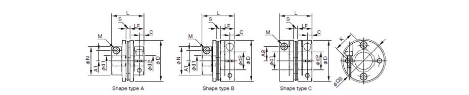
SFC-□DA2(L)
[Specifications]
| Model | shape TYPE | Rated torque [N・m] |
Misalignment | Max. rotation speed [min-1] |
Moment of inertia [kg・m2] |
Mass [kg] |
|||||
|---|---|---|---|---|---|---|---|---|---|---|---|
| Parallel[mm] | Angular [°] |
Axial [mm] |
|||||||||
| LMin. | LMax. | LMin. | LMax. | LMin. | LMax. | ||||||
| SFC-005DA2 | C | 0.6 | 0.03 | 0.20 | 0.5(On one side) | ±0.1 | 10000 | 0.33×10⁻⁶ | 0.62×10⁻⁶ | 0.009 | 0.017 |
| SFC-010DA2 | C | 1 | 0.08 | 0.44 | 1(On one side) | ±0.2 | 10000 | 0.72×10⁻⁶ | 1.38×10⁻⁶ | 0.014 | 0.026 |
| SFC-020DA2 | C | 2 | 0.10 | 0.46 | 1(On one side) | ±0.33 | 10000 | 3.02×10⁻⁶ | 5.30×10⁻⁶ | 0.031 | 0.054 |
| SFC-025DA2 | C | 4 | 0.09 | 0.46 | 1(On one side) | ±0.38 | 10000 | 4.55×10⁻⁶ | 7.95×10⁻⁶ | 0.036 | 0.061 |
| SFC-030DA2 | A | 5 | 0.11 | 0.48 | 1(On one side) | ±0.4 | 10000 | 6.09×10⁻⁶ | 12.80×10⁻⁶ | 0.046 | 0.085 |
| B | 8.11×10⁻⁶ | 14.82×10⁻⁶ | 0.053 | 0.091 | |||||||
| C | 10.22×10⁻⁶ | 16.93×10⁻⁶ | 0.061 | 0.099 | |||||||
| SFC-035DA2 | C | 10 | 0.15 | 0.54 | 1(On one side) | ±0.5 | 10000 | 23.85×10⁻⁶ | 35.97×10⁻⁶ | 0.108 | 0.161 |
| SFC-040DA2 | A | 12 | 0.15 | 0.54 | 1(On one side) | ±0.6 | 10000 | 25.06×10⁻⁶ | 44.76×10⁻⁶ | 0.107 | 0.174 |
| B | 30.89×10⁻⁶ | 50.62×10⁻⁶ | 0.116 | 0.182 | |||||||
| C | 37.58×10⁻⁶ | 57.31×10⁻⁶ | 0.130 | 0.197 | |||||||
| SFC-050DA2 | A | 25 | 0.16 | 0.63 | 1(On one side) | ±0.8 | 10000 | 77.42×10⁻⁶ | 144.3×10⁻⁶ | 0.205 | 0.347 |
| B | 97.97×10⁻⁶ | 164.8×10⁻⁶ | 0.225 | 0.365 | |||||||
| C | 120.8×10⁻⁶ | 187.6×10⁻⁶ | 0.252 | 0.394 | |||||||
| SFC-055DA2 | C | 40 | 0.16 | 0.60 | 1(On one side) | ±0.84 | 10000 | 226.8×10⁻⁶ | 325.0×10⁻⁶ | 0.378 | 0.538 |
| SFC-060DA2 | A | 60 | 0.19 | 0.63 | 1(On one side) | ±0.9 | 10000 | 210.8×10⁻⁶ | 340.1×10⁻⁶ | 0.382 | 0.567 |
| B | 269.9×10⁻⁶ | 399.2×10⁻⁶ | 0.424 | 0.609 | |||||||
| C | 333.5×10⁻⁶ | 462.8×10⁻⁶ | 0.484 | 0.669 | |||||||
* Types A / B / C are automatically specified by Miki Pulley according to the combination of bore diameters you select, and cannot be specified by the customer.
* Check the "Standard Bore Diameters" for SFC-□DA2 as there may be limitations on the rated torque caused by the holding power of the coupling shaft section.
* Max. rotation speed does not take into account dynamic balance.
* The moment of inertia and mass are measured for the maximum bore diameter.
* See "Specifications" for SFC-□DA2 for stiffness values.
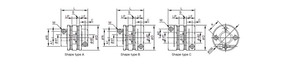
[Dimensions]
| Model | shape TYPE | d1 | d2 | D | N | L | LF | S | A1 | A2 | C | d3 | K | M | Tightening torque [N・m] |
||||
|---|---|---|---|---|---|---|---|---|---|---|---|---|---|---|---|---|---|---|---|
| Min. | Max. | Min. | Max. | Std. | Min. | Max. | |||||||||||||
| SFC-005DA2 | C | 3 | 6 | 3 | 6 | 16 | - | 23.2 | 21 | 40 | 7.85 | 1 | - | 4.8 | 2.5 | 6.5 | 6.5 | 1-M2 | 0.4 to 0.5 |
| SFC-010DA2 | C | 3 | 8 | 3 | 8 | 19 | - | 25.9 | 24 | 45 | 9.15 | 1.05 | - | 5.8(6) | 3.15 | 8.5 | 8.5 | 1-M2.5(M2) | 1.0 to 1.1(0.4 to 0.5) |
| SFC-020DA2 | C | 4 | 10 | 4 | 11 | 26 | - | 32.3 | 29 | 50 | 10.75 | 1.65 | - | 9.5 | 3.3 | 10.6 | 10.6 | 1-M2.5 | 1.0 to 1.1 |
| SFC-025DA2 | C | 5 | 14 | 5 | 14 | 29 | - | 32.8 | 29 | 50 | 10.75 | 1.9 | - | 11 | 3.3 | 15 | 14.5 | 1-M2.5 | 1.0 to 1.1 |
| SFC-030DA2 | A | 5 | 10 | 5 | 10 | 34 | 21.6 | 37.8 | 34 | 55 | 12.4 | 2.5 | 8 | - | 3.75 | 15 | 14.5 | 1-M3 | 1.5 to 1.9 |
| B | Over 10 | 16 | 12.5 | ||||||||||||||||
| C | Over 10 | 14 | - | - | |||||||||||||||
| SFC-035DA2 | C | 6 | 16 | 6 | 19 | 39 | - | 48 | 43 | 65 | 15.5 | 3 | - | 14 | 4.5 | 17 | 17 | 1-M4 | 3.4 to 4.1 |
| SFC-040DA2 | A | 8 | 15 | 8 | 15 | 44 | 29.6 | 48 | 43 | 65 | 15.5 | 3 | 11 | - | 4.5 | 20 | 19.5 | 1-M4 | 3.4 to 4.1 |
| B | Over 15 | 24 | 17 | ||||||||||||||||
| C | Over 15 | 19 | - | - | |||||||||||||||
| SFC-050DA2 | A | 8 | 19 | 8 | 19 | 56 | 38 | 59.8 | 53 | 80 | 20.5 | 2.4 | 14.5 | - | 6 | 26 | 26 | 1-M5 | 7.0 to 8.5 |
| B | Over 19 | 30 | 22 | ||||||||||||||||
| C | Over 19 | 25 | - | - | |||||||||||||||
| SFC-055DA2 | C | 10 | 30 | 10 | 30 | 63 | - | 68.7 | 60 | 85 | 24 | 2.6 | - | 23 | 7.75 | 31 | 31 | 1-M6 | 14 to 15 |
| SFC-060DA2 | A | 11 | 24 | 11 | 24 | 68 | 46 | 73.3 | 65 | 90 | 25.2 | 3.2 | 17.5 | - | 7.75 | 31 | 31 | 1-M6 | 14 to 15 |
| B | Over 24 | 35 | 26.5 | ||||||||||||||||
| C | Over 24 | 30 | - | - | |||||||||||||||
* Types A / B / C are automatically specified by Miki Pulley according to the combination of bore diameters you select, and cannot be specified by the customer.
* The nominal diameter for the clamping bolt M is equal to the quantity minus the nominal diameter of the screw threads, where the quantity is for a hub on one side.
* The figures in parentheses ( ) for the SFC-010 are the values when d1 or d2 is ø8 mm.
* Compatible lengths L range from the minimum L dimension to the maximum L dimension shown in the above table. Specify in 1 mm units.
* When the L dimension is shorter than the standard, the left/right clamping bolt phases will be off by 45°.
* Check "Standard Bore Diameters" for SFC-□DA2 for the standard bore diameters.

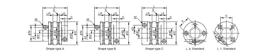
SFC-□SA2/DA2
[Dimensions]
| H9 keyway width standards | JS9 keyway width standards | ||||||||||||||||||||||||||||||||||||||||||||||||||||||||||||||||||||||||||||||||||||||||||||||||||||||||||||||||||||||||||||||||||||||||||||||||||||||||||||||||||||||||||||||||||||||||||||||||||||||||||||||||||||||||||||||||||||||||||||||||||||||||||||||||||||||||||||||||||||||||||||||||||||||||
|---|---|---|---|---|---|---|---|---|---|---|---|---|---|---|---|---|---|---|---|---|---|---|---|---|---|---|---|---|---|---|---|---|---|---|---|---|---|---|---|---|---|---|---|---|---|---|---|---|---|---|---|---|---|---|---|---|---|---|---|---|---|---|---|---|---|---|---|---|---|---|---|---|---|---|---|---|---|---|---|---|---|---|---|---|---|---|---|---|---|---|---|---|---|---|---|---|---|---|---|---|---|---|---|---|---|---|---|---|---|---|---|---|---|---|---|---|---|---|---|---|---|---|---|---|---|---|---|---|---|---|---|---|---|---|---|---|---|---|---|---|---|---|---|---|---|---|---|---|---|---|---|---|---|---|---|---|---|---|---|---|---|---|---|---|---|---|---|---|---|---|---|---|---|---|---|---|---|---|---|---|---|---|---|---|---|---|---|---|---|---|---|---|---|---|---|---|---|---|---|---|---|---|---|---|---|---|---|---|---|---|---|---|---|---|---|---|---|---|---|---|---|---|---|---|---|---|---|---|---|---|---|---|---|---|---|---|---|---|---|---|---|---|---|---|---|---|---|---|---|---|---|---|---|---|---|---|---|---|---|---|---|---|---|---|---|---|---|---|---|---|---|---|---|---|---|---|---|---|---|---|---|---|---|---|---|---|---|---|---|---|---|---|---|---|---|---|---|
| Nominal bore dia. | bore dia. d1/d2 [mm] |
Keyway width W1/W2 [mm] |
Keyway height T1/T2 [mm] |
Nominal bore dia. | bore dia. d1/d2 [mm] |
Keyway width W1/W2 [mm] |
Keyway height T1/T2 [mm] |
Nominal bore dia. | bore dia. d1/d2 [mm] |
Keyway width W1/W2 [mm] |
Keyway height T1/T2 [mm] |
Nominal bore dia. | bore dia. d1/d2 [mm] |
Keyway width W1/W2 [mm] |
Keyway height T1/T2 [mm] |
||||||||||||||||||||||||||||||||||||||||||||||||||||||||||||||||||||||||||||||||||||||||||||||||||||||||||||||||||||||||||||||||||||||||||||||||||||||||||||||||||||||||||||||||||||||||||||||||||||||||||||||||||||||||||||||||||||||||||||||||||||||||||||||||||||||||||||||||||||||||||
| bore dia. |
Shaft tolerance |
bore dia. |
Shaft tolerance |
bore dia. |
Shaft tolerance |
bore dia. |
Shaft tolerance |
||||||||||||||||||||||||||||||||||||||||||||||||||||||||||||||||||||||||||||||||||||||||||||||||||||||||||||||||||||||||||||||||||||||||||||||||||||||||||||||||||||||||||||||||||||||||||||||||||||||||||||||||||||||||||||||||||||||||||||||||||||||||||||||||||||||||||||||||||||||||||||||||||
| h7 | j6 | k6 | h7 | j6 | k6 | h7 | j6 | k6 | h7 | j6 | k6 | ||||||||||||||||||||||||||||||||||||||||||||||||||||||||||||||||||||||||||||||||||||||||||||||||||||||||||||||||||||||||||||||||||||||||||||||||||||||||||||||||||||||||||||||||||||||||||||||||||||||||||||||||||||||||||||||||||||||||||||||||||||||||||||||||||||||||||||||||||||||||||||||
| 8 | BH | - | KH | 8 | 3+0.0250 | 9.4+0.30 | 20 | BH | - | - | 20 | 6+0.0300 | 22.8+0.30 | 8 | BJ | - | KJ | 8 | 3±0.0125 | 9.4+0.30 | 20 | BJ | - | - | 20 | 6±0.0150 | 22.8+0.30 | ||||||||||||||||||||||||||||||||||||||||||||||||||||||||||||||||||||||||||||||||||||||||||||||||||||||||||||||||||||||||||||||||||||||||||||||||||||||||||||||||||||||||||||||||||||||||||||||||||||||||||||||||||||||||||||||||||||||||||||||||||||||||||||||||||||||||||||||
| 9 | BH | - | KH | 9 | 3+0.0250 | 10.4+0.30 | 22 | BH | JH | KH | 22 | 6+0.0300 | 24.8+0.30 | 9 | BJ | - | KJ | 9 | 3±0.0125 | 10.4+0.30 | 22 | BJ | JJ | KJ | 22 | 6±0.0150 | 24.8+0.30 | ||||||||||||||||||||||||||||||||||||||||||||||||||||||||||||||||||||||||||||||||||||||||||||||||||||||||||||||||||||||||||||||||||||||||||||||||||||||||||||||||||||||||||||||||||||||||||||||||||||||||||||||||||||||||||||||||||||||||||||||||||||||||||||||||||||||||||||||
| 10 | BH | - | - | 10 | 3+0.0250 | 11.4+0.30 | 24 | BH | JH | KH | 24 | 8+0.0360 | 27.3+0.30 | 10 | BJ | - | - | 10 | 3±0.0125 | 11.4+0.30 | 24 | BJ | JJ | KJ | 24 | 8±0.0180 | 27.3+0.30 | ||||||||||||||||||||||||||||||||||||||||||||||||||||||||||||||||||||||||||||||||||||||||||||||||||||||||||||||||||||||||||||||||||||||||||||||||||||||||||||||||||||||||||||||||||||||||||||||||||||||||||||||||||||||||||||||||||||||||||||||||||||||||||||||||||||||||||||||
| 11 | BH | - | - | 11 | 4+0.0300 | 12.8+0.30 | 25 | BH | - | - | 25 | 8+0.0360 | 28.3+0.30 | 11 | BJ | - | - | 11 | 4±0.0150 | 12.8+0.30 | 25 | BJ | - | - | 25 | 8±0.0180 | 28.3+0.30 | ||||||||||||||||||||||||||||||||||||||||||||||||||||||||||||||||||||||||||||||||||||||||||||||||||||||||||||||||||||||||||||||||||||||||||||||||||||||||||||||||||||||||||||||||||||||||||||||||||||||||||||||||||||||||||||||||||||||||||||||||||||||||||||||||||||||||||||||
| 12 | BH | - | - | 12 | 4+0.0300 | 13.8+0.30 | 28 | BH | JH | - | 28 | 8+0.0360 | 31.3+0.30 | 12 | BJ | - | - | 12 | 4±0.0150 | 13.8+0.30 | 28 | BJ | JJ | - | 28 | 8±0.0180 | 31.3+0.30 | ||||||||||||||||||||||||||||||||||||||||||||||||||||||||||||||||||||||||||||||||||||||||||||||||||||||||||||||||||||||||||||||||||||||||||||||||||||||||||||||||||||||||||||||||||||||||||||||||||||||||||||||||||||||||||||||||||||||||||||||||||||||||||||||||||||||||||||||
| 13 | BH | - | - | 13 | 5+0.0300 | 15.3+0.30 | 30 | BH | - | - | 30 | 8+0.0360 | 33.3+0.30 | 13 | BJ | - | - | 13 | 5±0.0150 | 15.3+0.30 | 30 | BJ | - | - | 30 | 8±0.0180 | 33.3+0.30 | ||||||||||||||||||||||||||||||||||||||||||||||||||||||||||||||||||||||||||||||||||||||||||||||||||||||||||||||||||||||||||||||||||||||||||||||||||||||||||||||||||||||||||||||||||||||||||||||||||||||||||||||||||||||||||||||||||||||||||||||||||||||||||||||||||||||||||||||
| 14 | BH | - | KH | 14 | 5+0.0300 | 16.3+0.30 | 32 | BH | - | KH | 32 | 10+0.0360 | 35.3+0.30 | 14 | BJ | - | KJ | 14 | 5±0.0150 | 16.3+0.30 | 32 | BJ | - | KJ | 32 | 10±0.0180 | 35.3+0.30 | ||||||||||||||||||||||||||||||||||||||||||||||||||||||||||||||||||||||||||||||||||||||||||||||||||||||||||||||||||||||||||||||||||||||||||||||||||||||||||||||||||||||||||||||||||||||||||||||||||||||||||||||||||||||||||||||||||||||||||||||||||||||||||||||||||||||||||||||
| 15 | BH | - | - | 15 | 5+0.0300 | 17.3+0.30 | 35 | BH | - | - | 35 | 10+0.0360 | 38.3+0.30 | 15 | BJ | - | - | 15 | 5±0.0150 | 17.3+0.30 | 35 | BJ | - | - | 35 | 10±0.0180 | 38.3+0.30 | ||||||||||||||||||||||||||||||||||||||||||||||||||||||||||||||||||||||||||||||||||||||||||||||||||||||||||||||||||||||||||||||||||||||||||||||||||||||||||||||||||||||||||||||||||||||||||||||||||||||||||||||||||||||||||||||||||||||||||||||||||||||||||||||||||||||||||||||
| 16 | BH | - | KH | 16 | 5+0.0300 | 18.3+0.30 | 38 | BH | - | KH | 38 | 10+0.0360 | 41.3+0.30 | 16 | BJ | - | KJ | 16 | 5±0.0150 | 18.3+0.30 | 38 | BJ | - | KJ | 38 | 10±0.0180 | 41.3+0.30 | ||||||||||||||||||||||||||||||||||||||||||||||||||||||||||||||||||||||||||||||||||||||||||||||||||||||||||||||||||||||||||||||||||||||||||||||||||||||||||||||||||||||||||||||||||||||||||||||||||||||||||||||||||||||||||||||||||||||||||||||||||||||||||||||||||||||||||||||
| 17 | BH | - | - | 17 | 5+0.0300 | 19.3+0.30 | 40 | BH | - | - | 40 | 12+0.4300 | 43.3+0.30 | 17 | BJ | - | - | 17 | 5±0.0150 | 19.3+0.30 | 40 | BJ | - | - | 40 | 12±0.0215 | 43.3+0.30 | ||||||||||||||||||||||||||||||||||||||||||||||||||||||||||||||||||||||||||||||||||||||||||||||||||||||||||||||||||||||||||||||||||||||||||||||||||||||||||||||||||||||||||||||||||||||||||||||||||||||||||||||||||||||||||||||||||||||||||||||||||||||||||||||||||||||||||||||
| 18 | BH | - | - | 18 | 6+0.0300 | 20.8+0.30 | 42 | BH | - | - | 42 | 12+0.4300 | 45.3+0.30 | 18 | BJ | - | - | 18 | 6±0.0150 | 20.8+0.30 | 42 | BJ | - | - | 42 | 12±0.0215 | 45.3+0.30 | ||||||||||||||||||||||||||||||||||||||||||||||||||||||||||||||||||||||||||||||||||||||||||||||||||||||||||||||||||||||||||||||||||||||||||||||||||||||||||||||||||||||||||||||||||||||||||||||||||||||||||||||||||||||||||||||||||||||||||||||||||||||||||||||||||||||||||||||
| 19 | BH | JH | KH | 19 | 6+0.0300 | 21.8+0.30 | 45 | BH | - | - | 45 | 14+0.4300 | 48.8+0.30 | 19 | BJ | JJ | KJ | 19 | 6±0.0150 | 21.8+0.30 | 45 | BJ | - | - | 45 | 14±0.0215 | 48.8+0.30 | ||||||||||||||||||||||||||||||||||||||||||||||||||||||||||||||||||||||||||||||||||||||||||||||||||||||||||||||||||||||||||||||||||||||||||||||||||||||||||||||||||||||||||||||||||||||||||||||||||||||||||||||||||||||||||||||||||||||||||||||||||||||||||||||||||||||||||||||
* Bore diameter of φ35 (nominal diameter B), the shaft tolerance is -0.025 to +0.010 .
* We can also handle standards not listed above. Consult MIKI PULLEY.
[Standard bore diameters]
| Standard (option) bore diameter, d1/d2 [mm] and restricted rated torque [N·m] | ||||||||||||||||||||||||||
|---|---|---|---|---|---|---|---|---|---|---|---|---|---|---|---|---|---|---|---|---|---|---|---|---|---|---|
| Nominal bore dia. | 8 | 9 | 9.525 | 10 | 11 | 12 | 13 | 14 | 15 | 16 | 17 | 18 | 19 | 20 | 22 | 24 | 25 | 28 | 30 | 32 | 35 | 38 | 40 | 42 | 45 | |
| Shaft tolerance h7(h6/g6) | B | ● | ● | ● | ● | ● | ● | ● | ● | ● | ● | ● | ● | ● | ● | ● | ● | ● | ● | ● | ● | ● | ● | ● | ● | ● |
| Shaft tolerance j6(option) | J | ○ | ○ | ○ | ○ | |||||||||||||||||||||
| Shaft tolerance k6(option) | K | ○ | ○ | ○ | ○ | ○ | ○ | ○ | ○ | ○ | ||||||||||||||||
| SFC-025 | d1 | ● | ● | ● | ● | ● | ● | ● | ● | |||||||||||||||||
| d2 | ● | ● | ● | ● | ● | ● | ● | ● | ||||||||||||||||||
| SFC-030 | d1 | ● | ● | ● | ● | ● | ● | ● | ● | |||||||||||||||||
| d2 | ● | ● | ● | ● | ● | ● | ● | ● | ● | ● | ||||||||||||||||
| SFC-035 | d1 | ● | ● | ● | ● | ● | ● | ● | ● | ● | ● | |||||||||||||||
| d2 | ● | ● | ● | ● | ● | ● | ● | ● | ● | ● | ● | ● | ● | |||||||||||||
| SFC-040 | d1 | 9 | ● | ● | ● | ● | ● | ● | ● | ● | ● | ● | ● | ● | ||||||||||||
| d2 | 9 | ● | ● | ● | ● | ● | ● | ● | ● | ● | ● | ● | ● | ● | ● | ● | ||||||||||
| SFC-050 | d1 | 18 | 20 | 22 | 22 | ● | ● | ● | ● | ● | ● | ● | ● | ● | ● | ● | ● | ● | ||||||||
| d2 | 18 | 20 | 22 | 22 | ● | ● | ● | ● | ● | ● | ● | ● | ● | ● | ● | ● | ● | ● | ● | |||||||
| SFC-055 | d1 | 31 | 34 | 36 | 38 | ● | ● | ● | ● | ● | ● | ● | ● | ● | ● | ● | ● | |||||||||
| d2 | 31 | 34 | 36 | 38 | ● | ● | ● | ● | ● | ● | ● | ● | ● | ● | ● | ● | ||||||||||
| SFC-060 | d1 | 50 | 51 | ● | ● | ● | ● | ● | ● | ● | ● | ● | ● | ● | ● | ● | ||||||||||
| d2 | 50 | 51 | ● | ● | ● | ● | ● | ● | ● | ● | ● | ● | ● | ● | ● | ● | ● | |||||||||
| SFC-080 | d1 | ● | ● | ● | ● | ● | ● | ● | ● | ● | ● | |||||||||||||||
| d2 | ● | ● | ● | ● | ● | ● | ● | ● | ● | ● | ● | ● | ||||||||||||||
| SFC-090 | d1 | ● | ● | ● | ● | ● | ● | ● | ||||||||||||||||||
| d2 | ● | ● | ● | ● | ● | ● | ● | ● | ● | |||||||||||||||||
| SFC-100 | d1 | 226 | ● | ● | ● | ● | ● | |||||||||||||||||||
| d2 | 226 | ● | ● | ● | ● | ● | ||||||||||||||||||||
* The shaft tolerance for standard bore diameter is h7 (h6 or g6): designation B. However, for a bore diameter of ø35, the shaft tolerance is -0.025 to +0.010.
* Shaft tolerances j6/k6: designations J/K are optional, and are only supported for bore diameters marked with ○ .
* Bore diameters marked with ● or numbers are supported as the standard bore diameters. Consult Miki Pulley regarding special arrangements which may be possible for other bore diameters.
* Bore diameters whose fields contain numbers are restricted in their rated torque by the holding power of the shaft connection component because the bore diameter is small. The numbers indicate the rated torque [N・m].
SFC-□SA2(CC/CF)
[Specifications]
| Model | shape TYPE | Rated torque [N・m] |
Misalignment | Max. rotation speed [min-1] |
Torsional stiffness [N・m/rad] |
Axial stiffness [N/mm] |
Moment of inertia [kg・m2] |
Mass [kg] |
||
|---|---|---|---|---|---|---|---|---|---|---|
| Parallel [mm] |
Angular [°] |
Axial [mm] |
||||||||
| SFC-020SA2 | C | 2 | 0.02 | 1 | ±0.15 | 10000 | 3700 | 64 | 2.39×10⁻⁶ | 0.025 |
| SFC-025SA2 | C | 4 | 0.02 | 1 | ±0.19 | 10000 | 5600 | 60 | 3.67×10⁻⁶ | 0.029 |
| SFC-030SA2 | A | 5 | 0.02 | 1 | ±0.2 | 10000 | 8000 | 64 | 4.09×10⁻⁶ | 0.034 |
| B | 6.11×10⁻⁶ | 0.040 | ||||||||
| C | 8.23×10⁻⁶ | 0.048 | ||||||||
| SFC-035SA2 | C | 10 | 0.02 | 1 | ±0.25 | 10000 | 18000 | 112 | 18.50×10⁻⁶ | 0.083 |
| SFC-040SA2 | A | 12 | 0.02 | 1 | ±0.3 | 10000 | 20000 | 80 | 16.71×10⁻⁶ | 0.077 |
| B | 22.59×10⁻⁶ | 0.085 | ||||||||
| C | 29.28×10⁻⁶ | 0.100 | ||||||||
| SFC-050SA2 | A | 25 | 0.02 | 1 | ±0.4 | 10000 | 32000 | 48 | 56.26×10⁻⁶ | 0.160 |
| B | 76.71×10⁻⁶ | 0.178 | ||||||||
| C | 99.38×10⁻⁶ | 0.207 | ||||||||
| SFC-055SA2 | C | 40 | 0.02 | 1 | ±0.42 | 10000 | 50000 | 43 | 188.7×10⁻⁶ | 0.315 |
| SFC-060SA2 | A | 60 | 0.02 | 1 | ±0.45 | 10000 | 70000 | 76.4 | 147.0×10⁻⁶ | 0.285 |
| B | 206.3×10⁻⁶ | 0.328 | ||||||||
| C | 270.0×10⁻⁶ | 0.387 | ||||||||
| SFC-080SA2 | C | 100 | 0.02 | 1 | ±0.55 | 10000 | 140000 | 128 | 716.3×10⁻⁶ | 0.720 |
* Types A / B / C are automatically specified by Miki Pulley according to the combination of bore diameters you select, and cannot be specified by the customer.
* Check the Standard Bore Diameter list as rated torque may be restricted by the holding power of the shaft connection component.
* Max. rotation speed does not take into account dynamic balance. * Torsional stiffness values given are measured values for the element alone.
* The moment of inertia and mass are measured for the maximum bore diameter.
[Dimensions]
| Model | shape TYPE | d1 | d2 | D | N | L | LF | S | A1 | A2 | C | K | M | Tightening torque [N・m] |
|||
|---|---|---|---|---|---|---|---|---|---|---|---|---|---|---|---|---|---|
| Min. | Max. | Min. | Max. | CC Low dust | CF Fluorine | ||||||||||||
| SFC-020SA2 | C | 5 | 10 | 5 | 11 | 26 | - | 23.15 | 10.75 | 1.65 | - | 9.5 | 3.3 | 10.6 | 1-M2.5 | 0.5 | 0.9 |
| SFC-025SA2 | C | 5 | 14 | 5 | 14 | 29 | - | 23.4 | 10.75 | 1.9 | - | 11 | 3.3 | 14.5 | 1-M2.5 | 0.5 | 0.9 |
| SFC-030SA2 | A | 5 | 10 | 5 | 10 | 34 | 21.6 | 27.3 | 12.4 | 2.5 | 8 | - | 3.75 | 14.5 | 1-M3 | 1.5 | 3.2 |
| B | Over 10 | 16 | 12.5 | ||||||||||||||
| C | Over 10 | 14 | - | - | |||||||||||||
| SFC-035SA2 | C | 6 | 16 | 6 | 19 | 39 | - | 34 | 15.5 | 3 | - | 14 | 4.5 | 17 | 1-M4 | 4 | 7.7 |
| SFC-040SA2 | A | 8 | 15 | 8 | 15 | 44 | 29.6 | 34 | 15.5 | 3 | 11 | - | 4.5 | 19.5 | 1-M4 | 4 | 7.7 |
| B | Over 15 | 24 | 17 | ||||||||||||||
| C | Over 15 | 19 | - | - | |||||||||||||
| SFC-050SA2 | A | 8 | 19 | 8 | 19 | 56 | 38 | 43.4 | 20.5 | 2.4 | 14.5 | - | 6 | 26 | 1-M5 | 7 | 12 |
| B | Over 19 | 30 | 22 | ||||||||||||||
| C | Over 19 | 25 | - | - | |||||||||||||
| SFC-055SA2 | C | 10 | 30 | 10 | 30 | 63 | - | 50.6 | 24 | 2.6 | - | 23 | 7.75 | 31 | 1-M6 | 13 | 22.5 |
| SFC-060SA2 | A | 11 | 24 | 11 | 24 | 68 | 46 | 53.6 | 25.2 | 3.2 | 17.5 | - | 7.75 | 31 | 1-M6 | 13 | 22.5 |
| B | Over 24 | 35 | 26.5 | ||||||||||||||
| C | Over 24 | 30 | - | - | |||||||||||||
| SFC-080SA2 | C | 18 | 35 | 18 | 40 | 82 | - | 68 | 30 | 8 | - | 28 | 9 | 38 | 1-M8 | 27 | 45 |
* Types A / B / C are automatically specified by Miki Pulley according to the combination of bore diameters you select, and cannot be specified by the customer.
* The K dimension is the inner diameter of the element. For d2 dimension exceeding this value, shaft can be inserted only up to LF dimension to the d2 side hub.
* The nominal diameter for the clamping bolt M is equal to the quantity minus the nominal diameter of the screw threads, where the quantity is for a hub on one side.
* You can choose from two types of grease for clamp bolts: low dust generation grease and fluorine grease.
[Standard bore diameters] (Low dust generation grease)
| Model | Standard bore diameter, d1/d2 [mm] and restricted rated torque [N・m] | |||||||||||||||||||||||||||
|---|---|---|---|---|---|---|---|---|---|---|---|---|---|---|---|---|---|---|---|---|---|---|---|---|---|---|---|---|
| d1/d2 | 5 | 6 | 6.35 | 7 | 8 | 9 | 9.525 | 10 | 11 | 12 | 13 | 14 | 15 | 16 | 17 | 18 | 19 | 20 | 22 | 24 | 25 | 28 | 30 | 32 | 35 | 38 | 40 | |
| SFC-020SA2 | d1 | 0.5 | 0.6 | 0.6 | 0.6 | 1.0 | 1.3 | 1.3 | ● | |||||||||||||||||||
| d2 | 0.5 | 0.6 | 0.6 | 0.6 | 1.0 | 1.3 | 1.3 | ● | ● | |||||||||||||||||||
| SFC-025SA2 | d1 | 0.5 | 0.5 | 0.5 | 0.5 | 0.8 | 0.8 | 0.8 | 1.8 | 1.8 | 2.3 | 2.3 | ● | |||||||||||||||
| d2 | 0.5 | 0.5 | 0.5 | 0.5 | 0.8 | 0.8 | 0.8 | 1.8 | 1.8 | 2.3 | 2.3 | ● | ||||||||||||||||
| SFC-030SA2 | d1 | 0.8 | 1.6 | 2 | 2.6 | 3.4 | 4.4 | 4.9 | ● | ● | ● | ● | ● | |||||||||||||||
| d2 | 0.8 | 1.6 | 2 | 2.6 | 3.4 | 4.4 | 4.9 | ● | ● | ● | ● | ● | ● | ● | ||||||||||||||
| SFC-035SA2 | d1 | 3.3 | 3.8 | 4.8 | 6.3 | 7.7 | 8.5 | 9.2 | ● | ● | ● | ● | ● | ● | ||||||||||||||
| d2 | 3.3 | 3.8 | 4.8 | 6.3 | 7.7 | 8.5 | 9.2 | ● | ● | ● | ● | ● | ● | ● | ● | ● | ||||||||||||
| SFC-040SA2 | d1 | 9 | 9 | 9 | 9 | 9 | ● | ● | ● | ● | ● | ● | ● | ● | ||||||||||||||
| d2 | 9 | 9 | 9 | 9 | 9 | ● | ● | ● | ● | ● | ● | ● | ● | ● | ● | ● | ||||||||||||
| SFC-050SA2 | d1 | 11 | 16 | 17 | 19 | 19 | 24 | 24 | 24 | ● | ● | ● | ● | ● | ● | ● | ● | ● | ||||||||||
| d2 | 11 | 16 | 17 | 19 | 19 | 24 | 24 | 24 | ● | ● | ● | ● | ● | ● | ● | ● | ● | ● | ● | |||||||||
| SFC-055SA2 | d1 | 20 | 24 | 29 | 33 | 37 | ● | ● | ● | ● | ● | ● | ● | ● | ● | ● | ● | |||||||||||
| d2 | 20 | 24 | 29 | 33 | 37 | ● | ● | ● | ● | ● | ● | ● | ● | ● | ● | ● | ||||||||||||
| SFC-060SA2 | d1 | 38 | 41 | 44 | 48 | 55 | 55 | 58 | ● | ● | ● | ● | ● | ● | ● | ● | ||||||||||||
| d2 | 38 | 41 | 44 | 48 | 55 | 55 | 58 | ● | ● | ● | ● | ● | ● | ● | ● | ● | ● | |||||||||||
| SFC-080SA2 | d1 | 54 | 60 | 65 | 75 | 85 | 90 | ● | ● | ● | ● | |||||||||||||||||
| d2 | 54 | 60 | 65 | 75 | 85 | 90 | ● | ● | ● | ● | ● | ● | ||||||||||||||||
* The shaft tolerance for standard bore diameter is h7 (h6 or g6): designation B. However, for a bore diameter of ø35, the shaft tolerance is -0.025 to +0.010.
* Bore diameters marked with ● or numbers are supported as the standard bore diameters. Consult Miki Pulley regarding special arrangements which may be possible for other bore diameters.
* Bore diameters whose fields contain numbers are restricted in their rated torque by the holding power of the shaft connection component because the bore diameter is small. The numbers indicate the rated torque [N・m].
[Standard bore diameters] (Fluorine grease)
| Model | Standard bore diameter, d1/d2 [mm] and restricted rated torque [N・m] | |||||||||||||||||||||||||||
|---|---|---|---|---|---|---|---|---|---|---|---|---|---|---|---|---|---|---|---|---|---|---|---|---|---|---|---|---|
| d1/d2 | 5 | 6 | 6.35 | 7 | 8 | 9 | 9.525 | 10 | 11 | 12 | 13 | 14 | 15 | 16 | 17 | 18 | 19 | 20 | 22 | 24 | 25 | 28 | 30 | 32 | 35 | 38 | 40 | |
| SFC-020SA2 | d1 | 0.7 | 0.7 | 0.7 | 0.8 | ● | ● | ● | ● | |||||||||||||||||||
| d2 | 0.7 | 0.7 | 0.7 | 0.8 | ● | ● | ● | ● | ● | |||||||||||||||||||
| SFC-025SA2 | d1 | 0.5 | 0.5 | 0.5 | 1.1 | 1.6 | 1.6 | 1.6 | 3.2 | 3.2 | ● | ● | ● | |||||||||||||||
| d2 | 0.5 | 0.5 | 0.5 | 1.1 | 1.6 | 1.6 | 1.6 | 3.2 | 3.2 | ● | ● | ● | ||||||||||||||||
| SFC-030SA2 | d1 | 0.8 | 2 | 2.4 | 3.1 | 4.3 | ● | ● | ● | ● | ● | ● | ● | |||||||||||||||
| d2 | 0.8 | 2 | 2.4 | 3.1 | 4.3 | ● | ● | ● | ● | ● | ● | ● | ● | ● | ||||||||||||||
| SFC-035SA2 | d1 | 3.6 | 5.2 | 6.4 | 8.2 | ● | ● | ● | ● | ● | ● | ● | ● | ● | ||||||||||||||
| d2 | 3.6 | 5.2 | 6.4 | 8.2 | ● | ● | ● | ● | ● | ● | ● | ● | ● | ● | ● | ● | ||||||||||||
| SFC-040SA2 | d1 | ● | ● | ● | ● | ● | ● | ● | ● | ● | ● | ● | ● | ● | ||||||||||||||
| d2 | ● | ● | ● | ● | ● | ● | ● | ● | ● | ● | ● | ● | ● | ● | ● | ● | ||||||||||||
| SFC-050SA2 | d1 | 11 | 17 | 19 | 20 | 22 | ● | ● | ● | ● | ● | ● | ● | ● | ● | ● | ● | ● | ||||||||||
| d2 | 11 | 17 | 19 | 20 | 22 | ● | ● | ● | ● | ● | ● | ● | ● | ● | ● | ● | ● | ● | ● | |||||||||
| SFC-055SA2 | d1 | 28 | 37 | ● | ● | ● | ● | ● | ● | ● | ● | ● | ● | ● | ● | ● | ● | |||||||||||
| d2 | 28 | 37 | ● | ● | ● | ● | ● | ● | ● | ● | ● | ● | ● | ● | ● | ● | ||||||||||||
| SFC-060SA2 | d1 | 40 | 44 | 49 | 53 | ● | ● | ● | ● | ● | ● | ● | ● | ● | ● | ● | ||||||||||||
| d2 | 40 | 44 | 49 | 53 | ● | ● | ● | ● | ● | ● | ● | ● | ● | ● | ● | ● | ● | |||||||||||
| SFC-080SA2 | d1 | 60 | 66 | 71 | 81 | 90 | 95 | ● | ● | ● | ● | |||||||||||||||||
| d2 | 60 | 66 | 71 | 81 | 90 | 95 | ● | ● | ● | ● | ● | ● | ||||||||||||||||
* The shaft tolerance for standard bore diameter is h7 (h6 or g6): designation B. However, for a bore diameter of ø35, the shaft tolerance is -0.025 to +0.010.
* Bore diameters marked with ● or numbers are supported as the standard bore diameters. Consult Miki Pulley regarding special arrangements which may be possible for other bore diameters.
* Bore diameters whose fields contain numbers are restricted in their rated torque by the holding power of the shaft connection component because the bore diameter is small. The numbers indicate the rated torque [N・m].
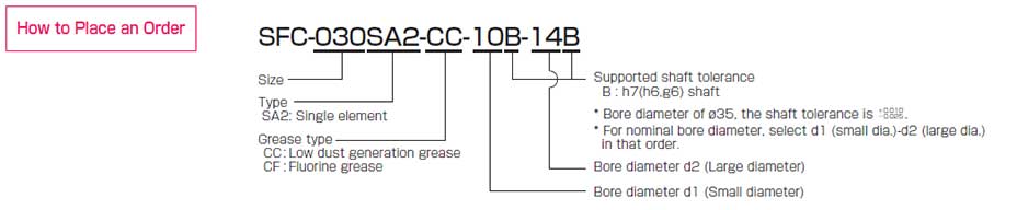
SFC-□DA2(CC/CF)
[Specifications]
| Model | shape TYPE | Rated torque [N・m] |
Misalignment | Max. rotation speed [min-1] |
Torsional stiffness [N・m/rad] |
Axial stiffness [N/mm] |
Moment of inertia [kg・m2] |
Mass [kg] |
||
|---|---|---|---|---|---|---|---|---|---|---|
| Parallel [mm] |
Angular [°] |
Axial [mm] |
||||||||
| SFC-020DA2 | C | 2 | 0.15 | 1(On one side) | ±0.33 | 10000 | 1850 | 32 | 3.43×10⁻⁶ | 0.035 |
| SFC-025DA2 | C | 4 | 0.16 | 1(On one side) | ±0.38 | 10000 | 2800 | 30 | 5.26×10⁻⁶ | 0.040 |
| SFC-030DA2 | A | 5 | 0.18 | 1(On one side) | ±0.4 | 10000 | 4000 | 32 | 7.46×10⁻⁶ | 0.054 |
| B | 9.49×10⁻⁶ | 0.060 | ||||||||
| C | 11.60×10⁻⁶ | 0.069 | ||||||||
| SFC-035DA2 | C | 10 | 0.24 | 1(On one side) | ±0.5 | 10000 | 9000 | 562 | 27.03×10⁻⁶ | 0.122 |
| SFC-040DA2 | A | 12 | 0.24 | 1(On one side) | ±0.6 | 10000 | 10000 | 40 | 30.03×10⁻⁶ | 0.124 |
| B | 35.81×10⁻⁶ | 0.132 | ||||||||
| C | 42.60×10⁻⁶ | 0.147 | ||||||||
| SFC-050DA2 | A | 25 | 0.28 | 1(On one side) | ±0.8 | 10000 | 16000 | 24 | 99.32×10⁻⁶ | 0.252 |
| B | 119.8×10⁻⁶ | 0.270 | ||||||||
| C | 142.4×10⁻⁶ | 0.299 | ||||||||
| SFC-055DA2 | C | 40 | 0.31 | 1(On one side) | ±0.84 | 10000 | 25000 | 21.5 | 262.3×10⁻⁶ | 0.436 |
| SFC-060DA2 | A | 60 | 0.34 | 1(On one side) | ±0.9 | 10000 | 35000 | 38.2 | 258.6×10⁻⁶ | 0.450 |
| B | 317.8×10⁻⁶ | 0.493 | ||||||||
| C | 381.6×10⁻⁶ | 0.552 | ||||||||
| SFC-080DA2 | C | 100 | 0.52 | 1(On one side) | ±1.10 | 10000 | 70000 | 64 | 1047×10-6 | 1.050 |
* Types A / B / C are automatically specified by Miki Pulley according to the combination of bore diameters you select, and cannot be specified by the customer.
* Check the Standard Bore Diameter list as rated torque may be restricted by the holding power of the shaft connection component.
* Max. rotation speed does not take into account dynamic balance. * Torsional stiffness values given are measured values for the element alone.
* The moment of inertia and mass are measured for the maximum bore diameter.
[Dimensions]
| Model | shape TYPE | d1 | d2 | D | N | L | LF | LP | S | A1 | A2 | C | d3 | K | M | Tightening torque [N・m] |
|||
|---|---|---|---|---|---|---|---|---|---|---|---|---|---|---|---|---|---|---|---|
| Min. | Max. | Min. | Max. | CC Low dust | CF Fluorine | ||||||||||||||
| SFC-020DA2 | C | 5 | 10 | 5 | 11 | 26 | - | 32.3 | 10.75 | 7.5 | 1.65 | - | 9.5 | 3.3 | 10.6 | 10.6 | 1-M2.5 | 0.5 | 0.9 |
| SFC-025DA2 | C | 5 | 14 | 5 | 14 | 29 | - | 32.8 | 10.75 | 7.5 | 1.9 | - | 11 | 3.3 | 15 | 14.5 | 1-M2.5 | 0.5 | 0.9 |
| SFC-030DA2 | A | 5 | 10 | 5 | 10 | 34 | 21.6 | 37.8 | 12.4 | 8 | 2.5 | 8 | - | 3.75 | 15 | 14.5 | 1-M3 | 1.5 | 3.2 |
| B | Over 10 | 16 | 12.5 | ||||||||||||||||
| C | Over 10 | 14 | - | - | |||||||||||||||
| SFC-035DA2 | C | 6 | 16 | 6 | 19 | 39 | - | 48 | 15.5 | 11 | 3 | - | 14 | 4.5 | 17 | 17 | 1-M4 | 4 | 7.7 |
| SFC-040DA2 | A | 8 | 15 | 8 | 15 | 44 | 29.6 | 48 | 15.5 | 11 | 3 | 11 | - | 4.5 | 20 | 19.5 | 1-M4 | 4 | 7.7 |
| B | Over 15 | 24 | 17 | ||||||||||||||||
| C | Over 15 | 24 | - | - | |||||||||||||||
| SFC-050DA2 | A | 8 | 19 | 8 | 19 | 56 | 38 | 59.8 | 20.5 | 14 | 2.4 | 14.5 | - | 6 | 26 | 26 | 1-M5 | 7 | 12 |
| B | Over 19 | 30 | 22 | ||||||||||||||||
| C | Over 19 | 25 | - | - | |||||||||||||||
| SFC-055DA2 | C | 10 | 30 | 10 | 30 | 63 | - | 68.7 | 24 | 15.5 | 2.6 | - | 23 | 7.75 | 31 | 31 | 1-M6 | 13 | 22.5 |
| SFC-060DA2 | A | 11 | 24 | 11 | 24 | 68 | 46 | 73.3 | 25.2 | 16.5 | 3.2 | 17.5 | - | 7.75 | 31 | 31 | 1-M6 | 13 | 22.5 |
| B | Over 24 | 35 | 26.5 | ||||||||||||||||
| C | Over 24 | 30 | - | - | |||||||||||||||
| SFC-080DA2 | C | 18 | 35 | 18 | 40 | 82 | - | 98 | 30 | 22 | 8 | - | 28 | 9 | 40 | 38 | 1-M8 | 27 | 45 |
* Types A / B / C are automatically specified by Miki Pulley according to the combination of bore diameters you select, and cannot be specified by the customer.
* The K dimension is the inner diameter of the element. For d2 dimension exceeding this value, shaft can be inserted only up to LF dimension to the d2 side hub.
* The nominal diameter for the clamping bolt M is equal to the quantity minus the nominal diameter of the screw threads, where the quantity is for a hub on one side.
* You can choose from two types of grease for clamp bolts: low dust generation grease and fluorine grease.
[Standard bore diameters] (Low dust generation grease)
| Model | Standard bore diameter, d1/d2 [mm] and restricted rated torque [N・m] | |||||||||||||||||||||||||||
|---|---|---|---|---|---|---|---|---|---|---|---|---|---|---|---|---|---|---|---|---|---|---|---|---|---|---|---|---|
| d1/d2 | 5 | 6 | 6.35 | 7 | 8 | 9 | 9.525 | 10 | 11 | 12 | 13 | 14 | 15 | 16 | 17 | 18 | 19 | 20 | 22 | 24 | 25 | 28 | 30 | 32 | 35 | 38 | 40 | |
| SFC-020DA2 | d1 | 0.5 | 0.6 | 0.6 | 0.6 | 1.0 | 1.3 | 1.3 | ● | |||||||||||||||||||
| d2 | 0.5 | 0.6 | 0.6 | 0.6 | 1.0 | 1.3 | 1.3 | ● | ● | |||||||||||||||||||
| SFC-025DA2 | d1 | 0.5 | 0.5 | 0.5 | 0.5 | 0.8 | 0.8 | 0.8 | 1.8 | 1.8 | 2.3 | 2.3 | ● | |||||||||||||||
| d2 | 0.5 | 0.5 | 0.5 | 0.5 | 0.8 | 0.8 | 0.8 | 1.8 | 1.8 | 2.3 | 2.3 | ● | ||||||||||||||||
| SFC-030DA2 | d1 | 0.8 | 1.6 | 2 | 2.6 | 3.4 | 4.4 | 4.9 | ● | ● | ● | ● | ● | |||||||||||||||
| d2 | 0.8 | 1.6 | 2 | 2.6 | 3.4 | 4.4 | 4.9 | ● | ● | ● | ● | ● | ● | ● | ||||||||||||||
| SFC-035DA2 | d1 | 3.3 | 3.8 | 4.8 | 6.3 | 7.7 | 8.5 | 9.2 | ● | ● | ● | ● | ● | ● | ||||||||||||||
| d2 | 3.3 | 3.8 | 4.8 | 6.3 | 7.7 | 8.5 | 9.2 | ● | ● | ● | ● | ● | ● | ● | ● | ● | ||||||||||||
| SFC-040DA2 | d1 | 9 | 9 | 9 | 9 | 9 | ● | ● | ● | ● | ● | ● | ● | ● | ||||||||||||||
| d2 | 9 | 9 | 9 | 9 | 9 | ● | ● | ● | ● | ● | ● | ● | ● | ● | ● | ● | ||||||||||||
| SFC-050DA2 | d1 | 11 | 16 | 17 | 19 | 19 | 24 | 24 | 24 | ● | ● | ● | ● | ● | ● | ● | ● | ● | ||||||||||
| d2 | 11 | 16 | 17 | 19 | 19 | 24 | 24 | 24 | ● | ● | ● | ● | ● | ● | ● | ● | ● | ● | ● | |||||||||
| SFC-055DA2 | d1 | 20 | 24 | 29 | 33 | 37 | ● | ● | ● | ● | ● | ● | ● | ● | ● | ● | ● | |||||||||||
| d2 | 20 | 24 | 29 | 33 | 37 | ● | ● | ● | ● | ● | ● | ● | ● | ● | ● | ● | ||||||||||||
| SFC-060DA2 | d1 | 38 | 41 | 44 | 48 | 55 | 55 | 58 | ● | ● | ● | ● | ● | ● | ● | ● | ||||||||||||
| d2 | 38 | 41 | 44 | 48 | 55 | 55 | 58 | ● | ● | ● | ● | ● | ● | ● | ● | ● | ● | |||||||||||
| SFC-080DA2 | d1 | 54 | 60 | 65 | 75 | 85 | 90 | ● | ● | ● | ● | |||||||||||||||||
| d2 | 54 | 60 | 65 | 75 | 85 | 90 | ● | ● | ● | ● | ● | ● | ||||||||||||||||
* The shaft tolerance for standard bore diameter is h7 (h6 or g6): designation B. However, for a bore diameter of ø35, the shaft tolerance is -0.025 to +0.010.
* Bore diameters marked with ● or numbers are supported as the standard bore diameters. Consult Miki Pulley regarding special arrangements which may be possible for other bore diameters.
* Bore diameters whose fields contain numbers are restricted in their rated torque by the holding power of the shaft connection component because the bore diameter is small. The numbers indicate the rated torque [N・m].
[Standard bore diameters] (Fluorine grease)
| Model | Standard bore diameter, d1/d2 [mm] and restricted rated torque [N・m] | |||||||||||||||||||||||||||
|---|---|---|---|---|---|---|---|---|---|---|---|---|---|---|---|---|---|---|---|---|---|---|---|---|---|---|---|---|
| d1/d2 | 5 | 6 | 6.35 | 7 | 8 | 9 | 9.525 | 10 | 11 | 12 | 13 | 14 | 15 | 16 | 17 | 18 | 19 | 20 | 22 | 24 | 25 | 28 | 30 | 32 | 35 | 38 | 40 | |
| SFC-020DA2 | d1 | 0.7 | 0.7 | 0.7 | 0.8 | ● | ● | ● | ● | |||||||||||||||||||
| d2 | 0.7 | 0.7 | 0.7 | 0.8 | ● | ● | ● | ● | ● | |||||||||||||||||||
| SFC-025DA2 | d1 | 0.5 | 0.5 | 0.5 | 1.1 | 1.6 | 1.6 | 1.6 | 3.2 | 3.2 | ● | ● | ● | |||||||||||||||
| d2 | 0.5 | 0.5 | 0.5 | 1.1 | 1.6 | 1.6 | 1.6 | 3.2 | 3.2 | ● | ● | ● | ||||||||||||||||
| SFC-030DA2 | d1 | 0.8 | 2 | 2.4 | 3.1 | 4.3 | ● | ● | ● | ● | ● | ● | ● | |||||||||||||||
| d2 | 0.8 | 2 | 2.4 | 3.1 | 4.3 | ● | ● | ● | ● | ● | ● | ● | ● | ● | ||||||||||||||
| SFC-035DA2 | d1 | 3.6 | 5.2 | 6.4 | 8.2 | ● | ● | ● | ● | ● | ● | ● | ● | ● | ||||||||||||||
| d2 | 3.6 | 5.2 | 6.4 | 8.2 | ● | ● | ● | ● | ● | ● | ● | ● | ● | ● | ● | ● | ||||||||||||
| SFC-040DA2 | d1 | ● | ● | ● | ● | ● | ● | ● | ● | ● | ● | ● | ● | ● | ||||||||||||||
| d2 | ● | ● | ● | ● | ● | ● | ● | ● | ● | ● | ● | ● | ● | ● | ● | ● | ||||||||||||
| SFC-050DA2 | d1 | 11 | 17 | 19 | 20 | 22 | ● | ● | ● | ● | ● | ● | ● | ● | ● | ● | ● | ● | ||||||||||
| d2 | 11 | 17 | 19 | 20 | 22 | ● | ● | ● | ● | ● | ● | ● | ● | ● | ● | ● | ● | ● | ● | |||||||||
| SFC-055DA2 | d1 | 28 | 37 | ● | ● | ● | ● | ● | ● | ● | ● | ● | ● | ● | ● | ● | ● | |||||||||||
| d2 | 28 | 37 | ● | ● | ● | ● | ● | ● | ● | ● | ● | ● | ● | ● | ● | ● | ||||||||||||
| SFC-060DA2 | d1 | 40 | 44 | 49 | 53 | ● | ● | ● | ● | ● | ● | ● | ● | ● | ● | ● | ||||||||||||
| d2 | 40 | 44 | 49 | 53 | ● | ● | ● | ● | ● | ● | ● | ● | ● | ● | ● | ● | ● | |||||||||||
| SFC-080DA2 | d1 | 60 | 66 | 71 | 81 | 90 | 95 | ● | ● | ● | ● | |||||||||||||||||
| d2 | 60 | 66 | 71 | 81 | 90 | 95 | ● | ● | ● | ● | ● | ● | ||||||||||||||||
* The shaft tolerance for standard bore diameter is h7 (h6 or g6): designation B. However, for a bore diameter of ø35, the shaft tolerance is -0.025 to +0.010.
* Bore diameters marked with ● or numbers are supported as the standard bore diameters. Consult Miki Pulley regarding special arrangements which may be possible for other bore diameters.
* Bore diameters whose fields contain numbers are restricted in their rated torque by the holding power of the shaft connection component because the bore diameter is small. The numbers indicate the rated torque [N・m].
![]()
![]()
![]()
![]()
![]()
![]()