SFF Models Specifications
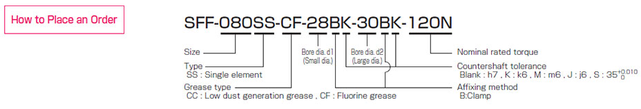
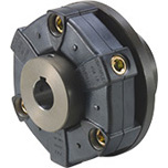
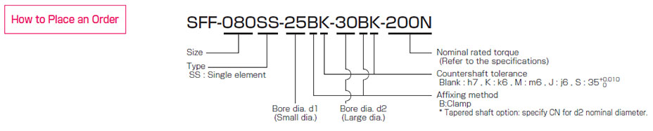
SFF-□SS (Clamping)
[Specifications]
| Model | Rated torque
[N・m] | Misalignment | Max.
rotation speed
[min-1] | Torsional
stiffness
[N・m/rad] | Axial
stiffness
[N/mm] | Moment
of inertia
[kg・m2] | Mass [kg] |
|---|
| Parallel [mm] | Angular [°] | Axial [mm] |
|---|
| SFF-040SS-□B-□B-8N | 8 | 0.02 | 1 | ±0.2 | 18000 | 15000 | 174 | 0.03×10⁻³ | 0.17 |
|---|
| SFF-040SS-□B-□B-12N | 12 | 0.02 | 1 | ±0.2 | 18000 | 15000 | 174 | 0.03×10⁻³ | 0.17 |
|---|
| SFF-050SS-□B-□B-25N | 25 | 0.02 | 1 | ±0.3 | 18000 | 32000 | 145 | 0.10×10⁻³ | 0.36 |
|---|
| SFF-060SS-□B-□B-60N | 60 | 0.02 | 1 | ±0.3 | 18000 | 104000 | 399 | 0.22×10⁻³ | 0.52 |
|---|
| SFF-060SS-□B-□B-80N | 80 | 0.02 | 1 | ±0.3 | 18000 | 104000 | 399 | 0.23×10⁻³ | 0.49 |
|---|
| SFF-070SS-□B-□B-90N | 90 | 0.02 | 1 | ±0.5 | 18000 | 240000 | 484 | 0.40×10⁻³ | 0.72 |
|---|
| SFF-070SS-□B-□B-100N | 100 | 0.02 | 1 | ±0.5 | 18000 | 240000 | 484 | 0.42×10⁻³ | 0.67 |
|---|
| SFF-080SS-□B-□B-150N | 150 | 0.02 | 1 | ±0.5 | 17000 | 120000 | 96 | 0.79×10⁻³ | 1.04 |
|---|
| SFF-080SS-□B-□B-200N | 200 | 0.02 | 1 | ±0.5 | 17000 | 310000 | 546 | 1.25×10⁻³ | 1.40 |
|---|
| SFF-090SS-□B-□B-250N | 250 | 0.02 | 1 | ±0.6 | 15000 | 520000 | 321 | 1.54×10⁻³ | 1.62 |
|---|
| SFF-090SS-□B-□B-300N | 300 | 0.02 | 1 | ±0.6 | 15000 | 520000 | 321 | 1.58×10⁻³ | 1.53 |
|---|
| SFF-100SS-□B-□B-450N | 450 | 0.02 | 1 | ±0.65 | 13000 | 740000 | 540 | 3.27×10⁻³ | 2.53 |
|---|
| SFF-120SS-□B-□B-600N | 600 | 0.02 | 1 | ±0.8 | 11000 | 970000 | 360 | 6.90×10⁻³ | 3.78 |
|---|
* Max. rotation speed does not take into account dynamic balance.
* Torsional stiffness values given are measured values for the element alone.
* The moment of inertia and mass are measured for the maximum bore diameter.
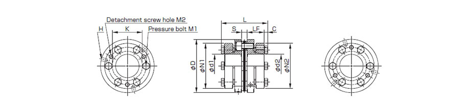
[Dimensions]

| Model | d1 [mm] | d2 [mm] | D [mm] | L [mm] | N1・N2 [mm] | LF [mm] | S [mm] | K [mm] | M1・M2 Qty
- Nominal dia. | M1・M2
Tightening
torque
[N・m] |
|---|
|
| SFF-040SS-□B-□B-8N | 8・9・9.525 | 8・9・9.525・10・11・12・14・15・16 | 38 | 38.9 | 33 | 17.5 | 3.9 | 17 | 2-M4 | 3.4 |
|---|
| SFF-040SS-□B-□B-12N | 10・11・12・14・15・16 | 10・11・12・14・15・16 | 38 | 38.9 | 33 | 17.5 | 3.9 | 17 | 2-M4 | 3.4 |
|---|
| SFF-050SS-□B-□B-25N | 10・11・12・14・15・16・17・18・19 | 10・11・12・14・15・16・17・18・19 | 48 | 48.4 | 42 | 21.5 | 5.4 | 20 | 2-M5 | 7 |
|---|
| SFF-060SS-□B-□B-60N | 12・14・15・16・17・18・19 | 12・14・15・16・17・18・19・20・22 | 58 | 53.4 | 44 | 24 | 5.4 | 32 | 2-M6 | 14 |
|---|
| - | 24・25・28 | 58 | 53.4 | 48 | 24 | 5.4 | 32 | 2-M5 | 7 |
| - | 30 | 58 | 53.4 | 52 | 24 | 5.4 | 32 | 2-M5 | 7 |
| SFF-060SS-□B-□B-80N | 20・22 | 20・22 | 58 | 53.4 | 44 | 24 | 5.4 | 32 | 2-M6 | 14 |
|---|
| 24・25・28 | 24・25・28 | 58 | 53.4 | 48 | 24 | 5.4 | 32 | 2-M5 | 7 |
| 30 | 30 | 58 | 53.4 | 52 | 24 | 5.4 | 32 | 2-M5 | 7 |
| SFF-070SS-□B-□B-90N | 18・19 | 18・19・20・22・24・25 | 68 | 55.9 | 47 | 25 | 5.9 | 38 | 2-M6 | 14 |
|---|
| - | 28・30・32・35 | 68 | 55.9 | 56 | 25 | 5.9 | 38 | 2-M6 | 14 |
| SFF-070SS-□B-□B-100N | 20・22・24・25 | 20・22・24・25 | 68 | 55.9 | 47 | 25 | 5.9 | 38 | 2-M6 | 14 |
|---|
| 28・30・32・35 | 28・30・32・35 | 68 | 55.9 | 56 | 25 | 5.9 | 38 | 2-M6 | 14 |
| SFF-080SS-□B-□B-150N | 22・24・25 | 22・24・25 | 78 | 68.3 | 53 | 30 | 8.3 | 37 | 2-M8 | 34 |
|---|
| 28・30・32・35 | 28・30・32・35 | 78 | 68.3 | 56 | 30 | 8.3 | 37 | 2-M6 | 14 |
| SFF-080SS-□B-□B-200N | 22・24・25 | 22・24・25 | 78 | 67.7 | 53 | 30 | 7.7 | 42 | 2-M8 | 34 |
|---|
| 28・30・32・35 | 28・30・32・35 | 78 | 67.7 | 70 | 30 | 7.7 | 42 | 2-M8 | 34 |
| 38 | 38 | 78 | 67.7 | 74 | 30 | 7.7 | 42 | 2-M8 | 34 |
| SFF-090SS-□B-□B-250N | 25・28 | 25・28・30・32 | 88 | 68.3 | 66 | 30 | 8.3 | 50 | 2-M8 | 34 |
|---|
| - | 35・38・40・42 | 88 | 68.3 | 74 | 30 | 8.3 | 50 | 2-M8 | 34 |
| SFF-090SS-□B-□B-300N | 30・32 | 30・32 | 88 | 68.3 | 66 | 30 | 8.3 | 50 | 2-M8 | 34 |
|---|
| 35・38・40・42 | 35・38・40・42 | 88 | 68.3 | 74 | 30 | 8.3 | 50 | 2-M8 | 34 |
| SFF-100SS-□B-□B-450N | 32・35・38・40・42・45・48 | 32・35・38・40・42・45・48 | 98 | 90.2 | 84 | 40 | 10.2 | 56 | 2-M10 | 68 |
|---|
| SFF-120SS-□B-□B-600N | 32・35・38・40・42・45 | 32・35・38・40・42・45 | 118 | 90.2 | 84 | 40 | 10.2 | 68 | 2-M10 | 68 |
|---|
| 48・50・55 | 48・50・55 | 118 | 90.2 | 100 | 40 | 10.2 | 68 | 2-M10 | 68 |
* Nominal diameter of clamping bolt M1/M2 is given as number of bolts - nominal diameter, and the number is the number for one hub.
[Standard bore diameter]
| Model | Standard bore diameter d1・d2[mm] |
|---|
Nominal
diameter | 8 | 9 | 9.525 | 10 | 11 | 12 | 14 | 15 | 16 | 17 | 18 | 19 | 20 | 22 | 24 | 25 | 28 | 30 | 32 | 35 | 38 | 40 | 42 | 45 | 48 | 50 | 55 |
|---|
| SFF-040SS-□B-□B-8N | d1 | ● | ● | ● | | | | | | | | | | | | | | | | | | | | | | | | |
|---|
| d2 | ● | ● | ● | ● | ● | ● | ● | ● | ● | | | | | | | | | | | | | | | | | | |
| SFF-040SS-□B-□B-12N | d1 | | | | ● | ● | ● | ● | ● | ● | | | | | | | | | | | | | | | | | | |
|---|
| d2 | | | | ● | ● | ● | ● | ● | ● | | | | | | | | | | | | | | | | | | |
| SFF-050SS-□B-□B-25N | d1 | | | | ● | ● | ● | ● | ● | ● | ● | ● | ● | | | | | | | | | | | | | | | |
|---|
| d2 | | | | ● | ● | ● | ● | ● | ● | ● | ● | ● | | | | | | | | | | | | | | | |
| SFF-060SS-□B-□B-60N | d1 | | | | | | ● | ● | ● | ● | ● | ● | ● | | | | | | | | | | | | | | | |
|---|
| d2 | | | | | | ● | ● | ● | ● | ● | ● | ● | ● | ● | ● | ● | ● | ● | | | | | | | | | |
| SFF-060SS-□B-□B-80N | d1 | | | | | | | | | | | | | ● | ● | ● | ● | ● | ● | | | | | | | | | |
|---|
| d2 | | | | | | | | | | | | | ● | ● | ● | ● | ● | ● | | | | | | | | | |
| SFF-070SS-□B-□B-90N | d1 | | | | | | | | | | | ● | ● | | | | | | | | | | | | | | | |
|---|
| d2 | | | | | | | | | | | ● | ● | ● | ● | ● | ● | ● | ● | ● | ● | | | | | | | |
| SFF-070SS-□B-□B-100N | d1 | | | | | | | | | | | | | ● | ● | ● | ● | ● | ● | ● | ● | | | | | | | |
|---|
| d2 | | | | | | | | | | | | | ● | ● | ● | ● | ● | ● | ● | ● | | | | | | | |
| SFF-080SS-□B-□B-150N | d1 | | | | | | | | | | | | | | ● | ● | ● | ● | ● | ● | ● | | | | | | | |
|---|
| d2 | | | | | | | | | | | | | | ● | ● | ● | ● | ● | ● | ● | | | | | | | |
| SFF-080SS-□B-□B-200N | d1 | | | | | | | | | | | | | | ● | ● | ● | ● | ● | ● | ● | ● | | | | | | |
|---|
| d2 | | | | | | | | | | | | | | ● | ● | ● | ● | ● | ● | ● | ● | | | | | | |
| SFF-090SS-□B-□B-250N | d1 | | | | | | | | | | | | | | | | ● | ● | | | | | | | | | | |
|---|
| d2 | | | | | | | | | | | | | | | | ● | ● | ● | ● | ● | ● | ● | ● | | | | |
| SFF-090SS-□B-□B-300N | d1 | | | | | | | | | | | | | | | | | | ● | ● | ● | ● | ● | ● | | | | |
|---|
| d2 | | | | | | | | | | | | | | | | | | ● | ● | ● | ● | ● | ● | | | | |
| SFF-100SS-□B-□B-450N | d1 | | | | | | | | | | | | | | | | | | | ● | ● | ● | ● | ● | ● | ● | | |
|---|
| d2 | | | | | | | | | | | | | | | | | | | ● | ● | ● | ● | ● | ● | ● | | |
| SFF-120SS-□B-□B-600N | d1 | | | | | | | | | | | | | | | | | | | ● | ● | ● | ● | ● | ● | ● | ● | ● |
|---|
| d2 | | | | | | | | | | | | | | | | | | | ● | ● | ● | ● | ● | ● | ● | ● | ● |
* The bore diameters marked with ● are supported as standard bore diameter.
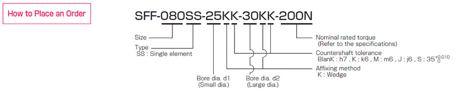
SFF-□SS (Wedge Coupling)
[Specifications]
| Model | Rated torque
[N・m] | Misalignment | Max.
rotation speed
[min-1] | Torsional
stiffness
[N・m/rad] | Axial
stiffness
[N/mm] | Moment
of inertia
[kg・m2] | Mass [kg] |
|---|
| Parallel [mm] | Angular [°] | Axial [mm] |
|---|
| SFF-070SS-□K-□K-100N | 100 | 0.02 | 1 | ±0.5 | 18000 | 240000 | 484 | 0.66×10⁻³ | 0.92 |
|---|
| SFF-080SS-□K-□K-150N | 150 | 0.02 | 1 | ±0.5 | 17000 | 120000 | 96 | 1.21×10⁻³ | 1.03 |
|---|
| SFF-080SS-□K-□K-200N | 200 | 0.02 | 1 | ±0.5 | 17000 | 310000 | 546 | 1.11×10⁻³ | 1.26 |
|---|
| SFF-090SS-□K-□K-300N | 300 | 0.02 | 1 | ±0.6 | 15000 | 520000 | 321 | 1.75×10⁻³ | 1.48 |
|---|
| SFF-100SS-□K-□K-450N | 450 | 0.02 | 1 | ±0.65 | 13000 | 740000 | 540 | 2.56×10⁻³ | 1.87 |
|---|
| SFF-120SS-□K-□K-600N | 600 | 0.02 | 1 | ±0.8 | 11000 | 970000 | 360 | 5.33×10⁻³ | 2.50 |
|---|
| SFF-140SS-□K-□K-800N | 800 | 0.02 | 1 | ±1.0 | 10000 | 1400000 | 360 | 10.28×10⁻³ | 4.66 |
|---|
| SFF-140SS-□K-□K-1000N | 1000 | 0.02 | 1 | ±1.0 | 10000 | 1400000 | 360 | 14.70×10⁻³ | 5.01 |
|---|
* Max. rotation speed does not take into account dynamic balance.
* Torsional stiffness values given are measured values for the element alone.
* The moment of inertia and mass are measured for the maximum bore diameter.
[Dimensions]
| Model | d1 [mm] | d2 [mm] | D [mm] | L [mm] | N1・N2 [mm] | LF [mm] | S [mm] | C [mm] | K [mm] | H [mm] | M1 Qty -
Nomina
dia. | M1
Tightening
torque
[N・m] | M2 Qty -
Nominal
dia. |
|---|
|
| SFF-070SS-□K-□K-100N | 18・19 | 18・19 | 68 | 62.9 | 53 | 23.5 | 5.9 | 5 | 38 | 3-5.1 | 6-M6 | 10 | 3-M6 |
|---|
| 20・22・24・25 | 20・22・24・25 | 68 | 62.9 | 58 | 23.5 | 5.9 | 5 | 38 | 3-5.1 | 6-M6 | 10 | 3-M6 |
| 28・30 | 28・30 | 68 | 62.9 | 63 | 23.5 | 5.9 | 5 | 38 | 3-5.1 | 6-M6 | 10 | 3-M6 |
| 32・35 | 32・35 | 68 | 62.9 | 68 | 23.5 | 5.9 | 5 | 38 | 3-5.1 | 6-M6 | 10 | 3-M6 |
| SFF-080SS-□K-□K-150N | 22・24・25 | 22・24・25 | 78 | 69.3 | 58 | 25.5 | 8.3 | 5 | 37 | 4-5.1 | 4-M6 | 10 | 2-M6 |
|---|
| 28・30 | 28・30 | 78 | 69.3 | 63 | 25.5 | 8.3 | 5 | 37 | 4-5.1 | 4-M6 | 10 | 2-M6 |
| 32・35 | 32・35 | 78 | 69.3 | 68 | 25.5 | 8.3 | 5 | 37 | 4-5.1 | 4-M6 | 10 | 2-M6 |
| - | 38 | 78 | 69.3 | 73 | 25.5 | 8.3 | 5 | 37 | 4-5.1 | 4-M6 | 10 | 2-M6 |
| SFF-080SS-□K-□K-200N | 22・24・25 | 22・24・25 | 78 | 68.7 | 58 | 25.5 | 7.7 | 5 | 42 | 3-5.1 | 6-M6 | 10 | 3-M6 |
|---|
| 28・30 | 28・30 | 78 | 68.7 | 63 | 25.5 | 7.7 | 5 | 42 | 3-5.1 | 6-M6 | 10 | 3-M6 |
| 32・35 | 32・35 | 78 | 68.7 | 68 | 25.5 | 7.7 | 5 | 42 | 3-5.1 | 6-M6 | 10 | 3-M6 |
| 38 | 38 | 78 | 68.7 | 73 | 25.5 | 7.7 | 5 | 42 | 3-5.1 | 6-M6 | 10 | 3-M6 |
| SFF-090SS-□K-□K-300N | 28・30 | 28・30 | 88 | 69.3 | 63 | 25.5 | 8.3 | 5 | 50 | 3-6.8 | 6-M6 | 10 | 3-M6 |
|---|
| 32・35 | 32・35 | 88 | 69.3 | 68 | 25.5 | 8.3 | 5 | 50 | 3-6.8 | 6-M6 | 10 | 3-M6 |
| 38・40・42 | 38・40・42 | 88 | 69.3 | 73 | 25.5 | 8.3 | 5 | 50 | 3-6.8 | 6-M6 | 10 | 3-M6 |
| 45 | 45 | 88 | 69.3 | 78 | 25.5 | 8.3 | 5 | 50 | 3-6.8 | 6-M6 | 10 | 3-M6 |
| 48 | 48 | 88 | 69.3 | 83 | 25.5 | 8.3 | 5 | 50 | 3-6.8 | 6-M6 | 10 | 3-M6 |
| SFF-100SS-□K-□K-450N | 32・35 | 32・35 | 98 | 75.2 | 68 | 27.5 | 10.2 | 5 | 56 | 3-6.8 | 6-M6 | 10 | 3-M6 |
|---|
| 38・40・42 | 38・40・42 | 98 | 75.2 | 73 | 27.5 | 10.2 | 5 | 56 | 3-6.8 | 6-M6 | 10 | 3-M6 |
| 45 | 45 | 98 | 75.2 | 78 | 27.5 | 10.2 | 5 | 56 | 3-6.8 | 6-M6 | 10 | 3-M6 |
| 48・50 | 48・50 | 98 | 75.2 | 83 | 27.5 | 10.2 | 5 | 56 | 3-6.8 | 6-M6 | 10 | 3-M6 |
| SFF-120SS-□K-□K-600N | 35 | 35 | 118 | 75.2 | 68 | 27.5 | 10.2 | 5 | 68 | 3-6.8 | 6-M6 | 10 | 3-M6 |
|---|
| 38・40・42 | 38・40・42 | 118 | 75.2 | 73 | 27.5 | 10.2 | 5 | 68 | 3-6.8 | 6-M6 | 10 | 3-M6 |
| 45 | 45 | 118 | 75.2 | 78 | 27.5 | 10.2 | 5 | 68 | 3-6.8 | 6-M6 | 10 | 3-M6 |
| 48・50・52 | 48・50・52 | 118 | 75.2 | 83 | 27.5 | 10.2 | 5 | 68 | 3-6.8 | 6-M6 | 10 | 3-M6 |
| 55 | 55 | 118 | 75.2 | 88 | 27.5 | 10.2 | 5 | 68 | 3-6.8 | 6-M6 | 10 | 3-M6 |
| 60・62・65 | 60・62・65 | 118 | 75.2 | 98 | 27.5 | 10.2 | 5 | 68 | 3-6.8 | 6-M6 | 10 | 3-M6 |
| - | 70 | 118 | 75.2 | 108 | 27.5 | 10.2 | 5 | 68 | 3-6.8 | 6-M6 | 10 | 3-M6 |
| SFF-140SS-□K-□K-800N | 35・38 | 35・38 | 138 | 94.6 | 83 | 36.5 | 10.6 | 5.5 | 78 | 3-8.6 | 6-M8 | 24 | 3-M8 |
|---|
| 40・42・45 | 40・42・45 | 138 | 94.6 | 88 | 36.5 | 10.6 | 5.5 | 78 | 3-8.6 | 6-M8 | 24 | 3-M8 |
| - | 48・50・52 | 138 | 94.6 | 98 | 36.5 | 10.6 | 5.5 | 78 | 3-8.6 | 6-M8 | 24 | 3-M8 |
| - | 55・60 | 138 | 94.6 | 108 | 36.5 | 10.6 | 5.5 | 78 | 3-8.6 | 6-M8 | 24 | 3-M8 |
| - | 62・65・70 | 138 | 94.6 | 118 | 36.5 | 10.6 | 5.5 | 78 | 3-8.6 | 6-M8 | 24 | 3-M8 |
| - | 75・80 | 138 | 94.6 | 128 | 36.5 | 10.6 | 5.5 | 78 | 3-8.6 | 6-M8 | 24 | 3-M8 |
| SFF-140SS-□K-□K-1000N | 48・50・52 | 48・50・52 | 138 | 94.6 | 98 | 36.5 | 10.6 | 5.5 | 78 | 3-8.6 | 6-M8 | 24 | 3-M8 |
|---|
| 55・60 | 55・60 | 138 | 94.6 | 108 | 36.5 | 10.6 | 5.5 | 78 | 3-8.6 | 6-M8 | 24 | 3-M8 |
| 62・65・70 | 62・65・70 | 138 | 94.6 | 118 | 36.5 | 10.6 | 5.5 | 78 | 3-8.6 | 6-M8 | 24 | 3-M8 |
| 75 | 75・80 | 138 | 94.6 | 128 | 36.5 | 10.6 | 5.5 | 78 | 3-8.6 | 6-M8 | 24 | 3-M8 |
* The nominal diameters of the pressure bolt M1 and detachment screw hole M2 are equal to the quantity minus the nominal diameter of the screw threads. The quantities of H, M1 and M2 are the same as the quantity for a hub on one side.
[Standard bore diameter]
| Model | Standard bore diameter d1・d2[mm] |
|---|
Nominal
diameter | 18 | 19 | 20 | 22 | 24 | 25 | 28 | 30 | 32 | 35 | 38 | 40 | 42 | 45 | 48 | 50 | 52 | 55 | 60 | 62 | 65 | 70 | 75 | 80 |
|---|
| SFF-070SS-□K-□K-100N | d1 | ● | ● | ● | ● | ● | ● | ● | ● | ● | ● | | | | | | | | | | | | | | |
|---|
| d2 | ● | ● | ● | ● | ● | ● | ● | ● | ● | ● | | | | | | | | | | | | | | |
| SFF-080SS-□K-□K-150N | d1 | | | | ● | ● | ● | ● | ● | ● | ● | | | | | | | | | | | | | | |
|---|
| d2 | | | | ● | ● | ● | ● | ● | ● | ● | ● | | | | | | | | | | | | | |
| SFF-080SS-□K-□K-200N | d1 | | | | ● | ● | ● | ● | ● | ● | ● | ● | | | | | | | | | | | | | |
|---|
| d2 | | | | ● | ● | ● | ● | ● | ● | ● | ● | | | | | | | | | | | | | |
| SFF-090SS-□K-□K-300N | d1 | | | | | | | ● | ● | ● | ● | ● | ● | ● | ● | ● | | | | | | | | | |
|---|
| d2 | | | | | | | ● | ● | ● | ● | ● | ● | ● | ● | ● | | | | | | | | | |
| SFF-100SS-□K-□K-450N | d1 | | | | | | | | | ● | ● | ● | ● | ● | ● | ● | ● | | | | | | | | |
|---|
| d2 | | | | | | | | | ● | ● | ● | ● | ● | ● | ● | ● | | | | | | | | |
| SFF-120SS-□K-□K-600N | d1 | | | | | | | | | | ● | ● | ● | ● | ● | ● | ● | ● | ● | ● | ● | ● | | | |
|---|
| d2 | | | | | | | | | | ● | ● | ● | ● | ● | ● | ● | ● | ● | ● | ● | ● | ● | | |
| SFF-140SS-□K-□K-800N | d1 | | | | | | | | | | ● | ● | ● | ● | ● | | | | | | | | | | |
|---|
| d2 | | | | | | | | | | ● | ● | ● | ● | ● | ● | ● | ● | ● | ● | ● | ● | ● | ● | ● |
| SFF-140SS-□K-□K-1000N | d1 | | | | | | | | | | | | | | | ● | ● | ● | ● | ● | ● | ● | ● | ● | |
|---|
| d2 | | | | | | | | | | | | | | | ● | ● | ● | ● | ● | ● | ● | ● | ● | ● |
* The bore diameters marked with ● are supported as standard bore diameter.
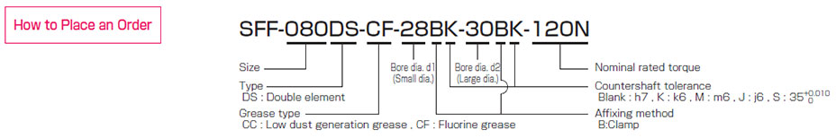
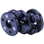
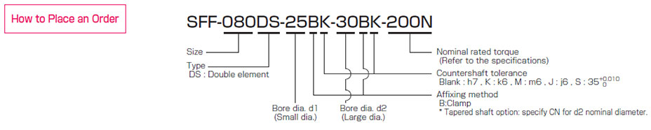
SFF-□DS (Clamping)
[Specifications]
| Model | Rated torque
[N・m] | Misalignment | Max.
rotation speed
[min-1] | Torsional
stiffness
[N・m/rad] | Axial
stiffness
[N/mm] | Moment
of inertia
[kg・m2] | Mass [kg] |
|---|
| Parallel [mm] | Angular [°] | Axial [mm] |
|---|
| SFF-040DS-□B-□B-8N | 8 | 0.10 | 1 (On one side) | ±0.4 | 14000 | 7500 | 87 | 0.04×10⁻³ | 0.22 |
|---|
| SFF-040DS-□B-□B-12N | 12 | 0.10 | 1 (On one side) | ±0.4 | 14000 | 7500 | 87 | 0.04×10⁻³ | 0.22 |
|---|
| SFF-050DS-□B-□B-25N | 25 | 0.20 | 1 (On one side) | ±0.6 | 14000 | 16000 | 72.5 | 0.13×10⁻³ | 0.46 |
|---|
| SFF-060DS-□B-□B-60N | 60 | 0.20 | 1 (On one side) | ±0.6 | 14000 | 52000 | 199.5 | 0.28×10⁻³ | 0.64 |
|---|
| SFF-060DS-□B-□B-80N | 80 | 0.20 | 1 (On one side) | ±0.6 | 14000 | 52000 | 199.5 | 0.29×10⁻³ | 0.61 |
|---|
| SFF-070DS-□B-□B-90N | 90 | 0.25 | 1 (On one side) | ±1.0 | 14000 | 120000 | 242 | 0.53×10⁻³ | 0.90 |
|---|
| SFF-070DS-□B-□B-100N | 100 | 0.25 | 1 (On one side) | ±1.0 | 14000 | 120000 | 242 | 0.55×10⁻³ | 0.85 |
|---|
| SFF-080DS-□B-□B-150N | 150 | 0.32 | 1 (On one side) | ±1.0 | 13000 | 60000 | 48 | 1.10×10⁻³ | 1.37 |
|---|
| SFF-080DS-□B-□B-200N | 200 | 0.31 | 1 (On one side) | ±1.0 | 13000 | 155000 | 273 | 1.50×10⁻³ | 1.72 |
|---|
| SFF-090DS-□B-□B-250N | 250 | 0.32 | 1 (On one side) | ±1.2 | 12000 | 260000 | 160.5 | 2.03×10⁻³ | 2.02 |
|---|
| SFF-090DS-□B-□B-300N | 300 | 0.32 | 1 (On one side) | ±1.2 | 12000 | 260000 | 160.5 | 2.10×10⁻³ | 1.92 |
|---|
| SFF-100DS-□B-□B-450N | 450 | 0.38 | 1 (On one side) | ±1.3 | 10000 | 370000 | 270 | 4.18×10⁻³ | 3.12 |
|---|
| SFF-120DS-□B-□B-600N | 600 | 0.38 | 1 (On one side) | ±1.6 | 9000 | 485000 | 180 | 8.87×10⁻³ | 4.60 |
|---|
* Max. rotation speed does not take into account dynamic balance.
* Torsional stiffness values given are measured values for the element alone.
* The moment of inertia and mass are measured for the maximum bore diameter.
[Dimensions]

| Model | d1
[mm] | d2
[mm] | D
[mm] | L
[mm] | N1・N2
[mm] | LF
[mm] | LP
[mm] | S
[mm] | d3
[mm] | K
[mm] | M1・M2 Qty
- Nominal dia. | M1・M2
Tightening
torque
[N・m] |
|---|
|
| SFF-040DS-□B-□B-8N | 8・9・9.525 | 8・9・9.525・10・11・12・14・15・16 | 38 | 48.8 | 33 | 17.5 | 6 | 3.9 | 17 | 17 | 2-M4 | 3.4 |
|---|
| SFF-040DS-□B-□B-12N | 10・11・12・14・15・16 | 10・11・12・14・15・16 | 38 | 48.8 | 33 | 17.5 | 6 | 3.9 | 17 | 17 | 2-M4 | 3.4 |
|---|
| SFF-050DS-□B-□B-25N | 10・11・12・14・15・16・17・18・19 | 10・11・12・14・15・16・17・18・19 | 48 | 60.8 | 42 | 21.5 | 7 | 5.4 | 20 | 20 | 2-M5 | 7 |
|---|
| SFF-060DS-□B-□B-60N | 12・14・15・16・17・18・19 | 12・14・15・16・17・18・19・20・22 | 58 | 65.8 | 44 | 24 | 7 | 5.4 | 31 | 32 | 2-M6 | 14 |
|---|
| - | 24・25・28 | 58 | 65.8 | 48 | 24 | 7 | 5.4 | 31 | 32 | 2-M5 | 7 |
| - | 30 | 58 | 65.8 | 52 | 24 | 7 | 5.4 | 31 | 32 | 2-M5 | 7 |
| SFF-060DS-□B-□B-80N | 20・22 | 20・22 | 58 | 65.8 | 44 | 24 | 7 | 5.4 | 31 | 32 | 2-M6 | 14 |
|---|
| 24・25・28 | 24・25・28 | 58 | 65.8 | 48 | 24 | 7 | 5.4 | 31 | 32 | 2-M5 | 7 |
| 30 | 30 | 58 | 65.8 | 52 | 24 | 7 | 5.4 | 31 | 32 | 2-M5 | 7 |
| SFF-070DS-□B-□B-90N | 18・19 | 18・19・20・22・24・25 | 68 | 69.8 | 47 | 25 | 8 | 5.9 | 37 | 38 | 2-M6 | 14 |
|---|
| - | 28・30・32・35 | 68 | 69.8 | 56 | 25 | 8 | 5.9 | 37 | 38 | 2-M6 | 14 |
| SFF-070DS-□B-□B-100N | 20・22・24・25 | 20・22・24・25 | 68 | 69.8 | 47 | 25 | 8 | 5.9 | 37 | 38 | 2-M6 | 14 |
|---|
| 28・30・32・35 | 28・30・32・35 | 68 | 69.8 | 56 | 25 | 8 | 5.9 | 37 | 38 | 2-M6 | 14 |
| SFF-080DS-□B-□B-150N | 22・24・25 | 22・24・25 | 78 | 86.6 | 53 | 30 | 10 | 8.3 | 40 | 37 | 2-M8 | 34 |
|---|
| 28・30・32・35 | 28・30・32・35 | 78 | 86.6 | 56 | 30 | 10 | 8.3 | 40 | 37 | 2-M6 | 14 |
| SFF-080DS-□B-□B-200N | 22・24・25 | 22・24・25 | 78 | 85.4 | 53 | 30 | 10 | 7.7 | 40 | 42 | 2-M8 | 34 |
|---|
| 28・30・32・35 | 28・30・32・35 | 78 | 85.4 | 70 | 30 | 10 | 7.7 | 40 | 42 | 2-M8 | 34 |
| 38 | 38 | 78 | 85.4 | 74 | 30 | 10 | 7.7 | 40 | 42 | 2-M8 | 34 |
| SFF-090DS-□B-□B-250N | 25・28 | 25・28・30・32 | 88 | 86.6 | 66 | 30 | 10 | 8.3 | 50 | 50 | 2-M8 | 34 |
|---|
| - | 35・38・40・42 | 88 | 86.6 | 74 | 30 | 10 | 8.3 | 50 | 50 | 2-M8 | 34 |
| SFF-090DS-□B-□B-300N | 30・32 | 30・32 | 88 | 86.6 | 66 | 30 | 10 | 8.3 | 50 | 50 | 2-M8 | 34 |
|---|
| 35・38・40・42 | 35・38・40・42 | 88 | 86.6 | 74 | 30 | 10 | 8.3 | 50 | 50 | 2-M8 | 34 |
| SFF-100DS-□B-□B-450N | 32・35・38・40・42・45・48 | 32・35・38・40・42・45・48 | 98 | 112.4 | 84 | 40 | 12 | 10.2 | 52 | 56 | 2-M10 | 68 |
|---|
| SFF-120DS-□B-□B-600N | 32・35・38・40・42・45 | 32・35・38・40・42・45 | 118 | 112.4 | 84 | 40 | 12 | 10.2 | 72 | 68 | 2-M10 | 68 |
|---|
| 48・50・55 | 48・50・55 | 118 | 112.4 | 100 | 40 | 12 | 10.2 | 72 | 68 | 2-M10 | 68 |
* Nominal diameter of clamping bolt M1/M2 is given as number of bolts - nominal diameter, and the number is the number for one hub.
[Standard bore diameter]
| Model | Standard bore diameter d1・d2[mm] |
|---|
Nominal
diameter | 8 | 9 | 9.525 | 10 | 11 | 12 | 14 | 15 | 16 | 17 | 18 | 19 | 20 | 22 | 24 | 25 | 28 | 30 | 32 | 35 | 38 | 40 | 42 | 45 | 48 | 50 | 55 |
|---|
| SFF-040DS-□B-□B-8N | d1 | ● | ● | ● | | | | | | | | | | | | | | | | | | | | | | | | |
|---|
| d2 | ● | ● | ● | ● | ● | ● | ● | ● | ● | | | | | | | | | | | | | | | | | | |
| SFF-040DS-□B-□B-12N | d1 | | | | ● | ● | ● | ● | ● | ● | | | | | | | | | | | | | | | | | | |
|---|
| d2 | | | | ● | ● | ● | ● | ● | ● | | | | | | | | | | | | | | | | | | |
| SFF-050DS-□B-□B-25N | d1 | | | | ● | ● | ● | ● | ● | ● | ● | ● | ● | | | | | | | | | | | | | | | |
|---|
| d2 | | | | ● | ● | ● | ● | ● | ● | ● | ● | ● | | | | | | | | | | | | | | | |
| SFF-060DS-□B-□B-60N | d1 | | | | | | ● | ● | ● | ● | ● | ● | ● | | | | | | | | | | | | | | | |
|---|
| d2 | | | | | | ● | ● | ● | ● | ● | ● | ● | ● | ● | ● | ● | ● | ● | | | | | | | | | |
| SFF-060DS-□B-□B-80N | d1 | | | | | | | | | | | | | ● | ● | ● | ● | ● | ● | | | | | | | | | |
|---|
| d2 | | | | | | | | | | | | | ● | ● | ● | ● | ● | ● | | | | | | | | | |
| SFF-070DS-□B-□B-90N | d1 | | | | | | | | | | | ● | ● | | | | | | | | | | | | | | | |
|---|
| d2 | | | | | | | | | | | ● | ● | ● | ● | ● | ● | ● | ● | ● | ● | | | | | | | |
| SFF-070DS-□B-□B-100N | d1 | | | | | | | | | | | | | ● | ● | ● | ● | ● | ● | ● | ● | | | | | | | |
|---|
| d2 | | | | | | | | | | | | | ● | ● | ● | ● | ● | ● | ● | ● | | | | | | | |
| SFF-080DS-□B-□B-150N | d1 | | | | | | | | | | | | | | ● | ● | ● | ● | ● | ● | ● | | | | | | | |
|---|
| d2 | | | | | | | | | | | | | | ● | ● | ● | ● | ● | ● | ● | | | | | | | |
| SFF-080DS-□B-□B-200N | d1 | | | | | | | | | | | | | | ● | ● | ● | ● | ● | ● | ● | ● | | | | | | |
|---|
| d2 | | | | | | | | | | | | | | ● | ● | ● | ● | ● | ● | ● | ● | | | | | | |
| SFF-090DS-□B-□B-250N | d1 | | | | | | | | | | | | | | | | ● | ● | | | | | | | | | | |
|---|
| d2 | | | | | | | | | | | | | | | | ● | ● | ● | ● | ● | ● | ● | ● | | | | |
| SFF-090DS-□B-□B-300N | d1 | | | | | | | | | | | | | | | | | | ● | ● | ● | ● | ● | ● | | | | |
|---|
| d2 | | | | | | | | | | | | | | | | | | ● | ● | ● | ● | ● | ● | | | | |
| SFF-100DS-□B-□B-450N | d1 | | | | | | | | | | | | | | | | | | | ● | ● | ● | ● | ● | ● | ● | | |
|---|
| d2 | | | | | | | | | | | | | | | | | | | ● | ● | ● | ● | ● | ● | ● | | |
| SFF-120DS-□B-□B-600N | d1 | | | | | | | | | | | | | | | | | | | ● | ● | ● | ● | ● | ● | ● | ● | ● |
|---|
| d2 | | | | | | | | | | | | | | | | | | | ● | ● | ● | ● | ● | ● | ● | ● | ● |
* The bore diameters marked with ● are supported as standard bore diameter.
SFF-□DS (Wedge Coupling)
[Specifications]
| Model | Rated torque
[N・m] | Misalignment | Max.
rotation speed
[min-1] | Torsional
stiffness
[N・m/rad] | Axial
stiffness
[N/mm] | Moment
of inertia
[kg・m2] | Mass [kg] |
|---|
| Parallel [mm] | Angular [°] | Axial [mm] |
|---|
| SFF-070DS-□K-□K-100N | 100 | 0.25 | 1 (On one side) | ±1.0 | 14000 | 120000 | 242 | 0.80×10⁻³ | 1.10 |
|---|
| SFF-080DS-□K-□K-150N | 150 | 0.32 | 1 (On one side) | ±1.0 | 13000 | 60000 | 48 | 1.36×10⁻³ | 1.56 |
|---|
| SFF-080DS-□K-□K-200N | 200 | 0.31 | 1 (On one side) | ±1.0 | 13000 | 155000 | 273 | 1.42×10⁻³ | 1.60 |
|---|
| SFF-090DS-□K-□K-300N | 300 | 0.32 | 1 (On one side) | ±1.2 | 12000 | 260000 | 160.5 | 2.24×10⁻³ | 1.87 |
|---|
| SFF-100DS-□K-□K-450N | 450 | 0.38 | 1 (On one side) | ±1.3 | 10000 | 370000 | 270 | 3.51×10⁻³ | 2.49 |
|---|
| SFF-120DS-□K-□K-600N | 600 | 0.38 | 1 (On one side) | ±1.6 | 9000 | 485000 | 180 | 7.17×10⁻³ | 3.29 |
|---|
| SFF-140DS-□K-□K-800N | 800 | 0.44 | 1 (On one side) | ±2.0 | 8000 | 700000 | 180 | 14.68×10⁻³ | 6.05 |
|---|
| SFF-140DS-□K-□K-1000N | 1000 | 0.44 | 1 (On one side) | ±2.0 | 8000 | 700000 | 180 | 19.11×10⁻³ | 6.39 |
|---|
* Max. rotation speed does not take into account dynamic balance.
* Torsional stiffness values given are measured values for the element alone.
* The moment of inertia and mass are measured for the maximum bore diameter.
[Dimensions]
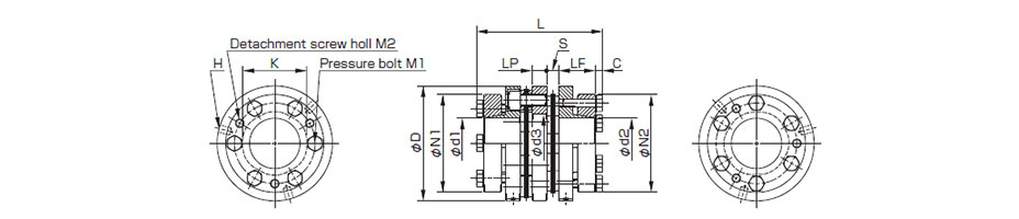
| Model | d1 [mm] | d2 [mm] | D [mm] | L [mm] | N1・N2 [mm] | LF [mm] | LP [mm] | S [mm] | C [mm] | d3 [mm] | K [mm] | H [mm] | M1 Qty -
Nomina
dia. | M1
Tightening
torque
[N・m] | M2 Qty -
Nominal
dia. |
|---|
|
| SFF-070DS-□K-□K-100N | 18・19 | 18・19 | 68 | 76.8 | 53 | 23.5 | 8 | 5.9 | 5 | 37 | 38 | 3-5.1 | 6-M6 | 10 | 3-M6 |
|---|
| 20・22・24・25 | 20・22・24・25 | 68 | 76.8 | 58 | 23.5 | 8 | 5.9 | 5 | 37 | 38 | 3-5.1 | 6-M6 | 10 | 3-M6 |
| 28・30 | 28・30 | 68 | 76.8 | 63 | 23.5 | 8 | 5.9 | 5 | 37 | 38 | 3-5.1 | 6-M6 | 10 | 3-M6 |
| 32・35 | 32・35 | 68 | 76.8 | 68 | 23.5 | 8 | 5.9 | 5 | 37 | 38 | 3-5.1 | 6-M6 | 10 | 3-M6 |
| SFF-080DS-□K-□K-150N | 22・24・25 | 22・24・25 | 78 | 87.6 | 58 | 25.5 | 10 | 8.3 | 5 | 40 | 37 | 4-5.1 | 4-M6 | 10 | 2-M6 |
|---|
| 28・30 | 28・30 | 78 | 87.6 | 63 | 25.5 | 10 | 8.3 | 5 | 40 | 37 | 4-5.1 | 4-M6 | 10 | 2-M6 |
| 32・35 | 32・35 | 78 | 87.6 | 68 | 25.5 | 10 | 8.3 | 5 | 40 | 37 | 4-5.1 | 4-M6 | 10 | 2-M6 |
| - | 38 | 78 | 87.6 | 73 | 25.5 | 10 | 8.3 | 5 | 40 | 37 | 4-5.1 | 4-M6 | 10 | 2-M6 |
| SFF-080DS-□K-□K-200N | 22・24・25 | 22・24・25 | 78 | 86.4 | 58 | 25.5 | 10 | 7.7 | 5 | 40 | 42 | 3-5.1 | 6-M6 | 10 | 3-M6 |
|---|
| 28・30 | 28・30 | 78 | 86.4 | 63 | 25.5 | 10 | 7.7 | 5 | 40 | 42 | 3-5.1 | 6-M6 | 10 | 3-M6 |
| 32・35 | 32・35 | 78 | 86.4 | 68 | 25.5 | 10 | 7.7 | 5 | 40 | 42 | 3-5.1 | 6-M6 | 10 | 3-M6 |
| 38 | 38 | 78 | 86.4 | 73 | 25.5 | 10 | 7.7 | 5 | 40 | 42 | 3-5.1 | 6-M6 | 10 | 3-M6 |
| SFF-090DS-□K-□K-300N | 28・30 | 28・30 | 88 | 87.6 | 63 | 25.5 | 10 | 8.3 | 5 | 50 | 50 | 3-6.8 | 6-M6 | 10 | 3-M6 |
|---|
| 32・35 | 32・35 | 88 | 87.6 | 68 | 25.5 | 10 | 8.3 | 5 | 50 | 50 | 3-6.8 | 6-M6 | 10 | 3-M6 |
| 38・40・42 | 38・40・42 | 88 | 87.6 | 73 | 25.5 | 10 | 8.3 | 5 | 50 | 50 | 3-6.8 | 6-M6 | 10 | 3-M6 |
| 45 | 45 | 88 | 87.6 | 78 | 25.5 | 10 | 8.3 | 5 | 50 | 50 | 3-6.8 | 6-M6 | 10 | 3-M6 |
| 48 | 48 | 88 | 87.6 | 83 | 25.5 | 10 | 8.3 | 5 | 50 | 50 | 3-6.8 | 6-M6 | 10 | 3-M6 |
| SFF-100DS-□K-□K-450N | 32・35 | 32・35 | 98 | 97.4 | 68 | 27.5 | 12 | 10.2 | 5 | 52 | 56 | 3-6.8 | 6-M6 | 10 | 3-M6 |
|---|
| 38・40・42 | 38・40・42 | 98 | 97.4 | 73 | 27.5 | 12 | 10.2 | 5 | 52 | 56 | 3-6.8 | 6-M6 | 10 | 3-M6 |
| 45 | 45 | 98 | 97.4 | 78 | 27.5 | 12 | 10.2 | 5 | 52 | 56 | 3-6.8 | 6-M6 | 10 | 3-M6 |
| 48・50 | 48・50 | 98 | 97.4 | 83 | 27.5 | 12 | 10.2 | 5 | 52 | 56 | 3-6.8 | 6-M6 | 10 | 3-M6 |
| SFF-120DS-□K-□K-600N | 35 | 35 | 118 | 97.4 | 68 | 27.5 | 12 | 10.2 | 5 | 72 | 68 | 3-6.8 | 6-M6 | 10 | 3-M6 |
|---|
| 38・40・42 | 38・40・42 | 118 | 97.4 | 73 | 27.5 | 12 | 10.2 | 5 | 72 | 68 | 3-6.8 | 6-M6 | 10 | 3-M6 |
| 45 | 45 | 118 | 97.4 | 78 | 27.5 | 12 | 10.2 | 5 | 72 | 68 | 3-6.8 | 6-M6 | 10 | 3-M6 |
| 48・50・52 | 48・50・52 | 118 | 97.4 | 83 | 27.5 | 12 | 10.2 | 5 | 72 | 68 | 3-6.8 | 6-M6 | 10 | 3-M6 |
| 55 | 55 | 118 | 97.4 | 88 | 27.5 | 12 | 10.2 | 5 | 72 | 68 | 3-6.8 | 6-M6 | 10 | 3-M6 |
| 60・62・65 | 60・62・65 | 118 | 97.4 | 98 | 27.5 | 12 | 10.2 | 5 | 72 | 68 | 3-6.8 | 6-M6 | 10 | 3-M6 |
| - | 70 | 118 | 97.4 | 108 | 27.5 | 12 | 10.2 | 5 | 72 | 68 | 3-6.8 | 6-M6 | 10 | 3-M6 |
| SFF-140DS-□K-□K-800N | 35・38 | 35・38 | 138 | 120 | 83 | 36.5 | 15 | 10.6 | 5.5 | 80 | 78 | 3-8.6 | 6-M8 | 24 | 3-M8 |
|---|
| 40・42・45 | 40・42・45 | 138 | 120 | 88 | 36.5 | 15 | 10.6 | 5.5 | 80 | 78 | 3-8.6 | 6-M8 | 24 | 3-M8 |
| - | 48・50・52 | 138 | 120 | 98 | 36.5 | 15 | 10.6 | 5.5 | 80 | 78 | 3-8.6 | 6-M8 | 24 | 3-M8 |
| - | 55・60 | 138 | 120 | 108 | 36.5 | 15 | 10.6 | 5.5 | 80 | 78 | 3-8.6 | 6-M8 | 24 | 3-M8 |
| - | 62・65・70 | 138 | 120 | 118 | 36.5 | 15 | 10.6 | 5.5 | 80 | 78 | 3-8.6 | 6-M8 | 24 | 3-M8 |
| - | 75・80 | 138 | 120 | 128 | 36.5 | 15 | 10.6 | 5.5 | 80 | 78 | 3-8.6 | 6-M8 | 24 | 3-M8 |
| SFF-140DS-□K-□K-1000N | 48・50・52 | 48・50・52 | 138 | 120 | 98 | 36.5 | 15 | 10.6 | 5.5 | 80 | 78 | 3-8.6 | 6-M8 | 24 | 3-M8 |
|---|
| 55・60 | 55・60 | 138 | 120 | 108 | 36.5 | 15 | 10.6 | 5.5 | 80 | 78 | 3-8.6 | 6-M8 | 24 | 3-M8 |
| 62・65・70 | 62・65・70 | 138 | 120 | 118 | 36.5 | 15 | 10.6 | 5.5 | 80 | 78 | 3-8.6 | 6-M8 | 24 | 3-M8 |
| 75 | 75・80 | 138 | 120 | 128 | 36.5 | 15 | 10.6 | 5.5 | 80 | 78 | 3-8.6 | 6-M8 | 24 | 3-M8 |
* The nominal diameters of the pressure bolt M1 and detachment screw hole M2 are equal to the quantity minus the nominal diameter of the screw threads. The quantities of H, M1 and M2 are the same as the quantity for a hub on one side.
[Standard bore diameter]
| Model | Standard bore diameter d1・d2[mm] |
|---|
Nominal
diameter | 18 | 19 | 20 | 22 | 24 | 25 | 28 | 30 | 32 | 35 | 38 | 40 | 42 | 45 | 48 | 50 | 52 | 55 | 60 | 62 | 65 | 70 | 75 | 80 |
|---|
| SFF-070DS-□K-□K-100N | d1 | ● | ● | ● | ● | ● | ● | ● | ● | ● | ● | | | | | | | | | | | | | | |
|---|
| d2 | ● | ● | ● | ● | ● | ● | ● | ● | ● | ● | | | | | | | | | | | | | | |
| SFF-080DS-□K-□K-150N | d1 | | | | ● | ● | ● | ● | ● | ● | ● | | | | | | | | | | | | | | |
|---|
| d2 | | | | ● | ● | ● | ● | ● | ● | ● | ● | | | | | | | | | | | | | |
| SFF-080DS-□K-□K-200N | d1 | | | | ● | ● | ● | ● | ● | ● | ● | ● | | | | | | | | | | | | | |
|---|
| d2 | | | | ● | ● | ● | ● | ● | ● | ● | ● | | | | | | | | | | | | | |
| SFF-090DS-□K-□K-300N | d1 | | | | | | | ● | ● | ● | ● | ● | ● | ● | ● | ● | | | | | | | | | |
|---|
| d2 | | | | | | | ● | ● | ● | ● | ● | ● | ● | ● | ● | | | | | | | | | |
| SFF-100DS-□K-□K-450N | d1 | | | | | | | | | ● | ● | ● | ● | ● | ● | ● | ● | | | | | | | | |
|---|
| d2 | | | | | | | | | ● | ● | ● | ● | ● | ● | ● | ● | | | | | | | | |
| SFF-120DS-□K-□K-600N | d1 | | | | | | | | | | ● | ● | ● | ● | ● | ● | ● | ● | ● | ● | ● | ● | | | |
|---|
| d2 | | | | | | | | | | ● | ● | ● | ● | ● | ● | ● | ● | ● | ● | ● | ● | ● | | |
| SFF-140DS-□K-□K-800N | d1 | | | | | | | | | | ● | ● | ● | ● | ● | | | | | | | | | | |
|---|
| d2 | | | | | | | | | | ● | ● | ● | ● | ● | ● | ● | ● | ● | ● | ● | ● | ● | ● | ● |
| SFF-140DS-□K-□K-1000N | d1 | | | | | | | | | | | | | | | ● | ● | ● | ● | ● | ● | ● | ● | ● | |
|---|
| d2 | | | | | | | | | | | | | | | ● | ● | ● | ● | ● | ● | ● | ● | ● | ● |
* The bore diameters marked with ● are supported as standard bore diameter.
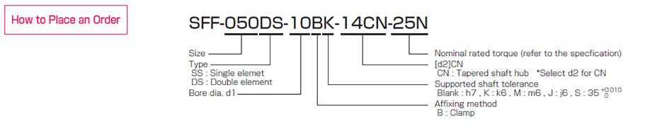
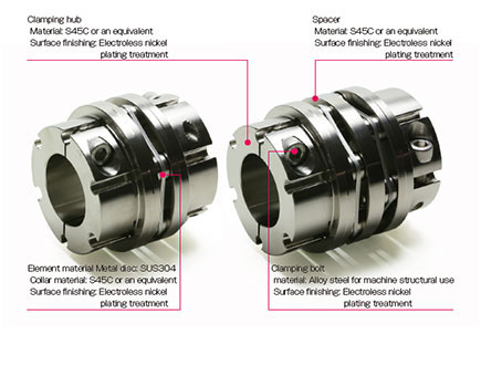
Options of SFF Models
Tapered shaft supported Single elementSupports servo motor tapered shafts.
[Specifications]
| Model |
Rated Torque
[N・m] |
Misalignment |
Max. rotation speed
[min-1] |
Torsional stiffness
[N・m/rad] |
Axial stiffness
[N/mm] |
Moment of inertia
[kg/m2] |
Mass
[kg] |
| Parallel [mm] |
Angular [°] |
Axial [mm] |
| SFF-040SS-□B-11CN-8N |
8 |
0.02 |
1 |
±0.2 |
18000 |
15000 |
174 |
0.03×10⁻³ |
0.2 |
| SFF-040SS-□B-11CN-12N |
12 |
0.02 |
1 |
±0.2 |
18000 |
15000 |
174 |
0.03×10⁻³ |
0.18 |
| SFF-050SS-□B-14CN-25N |
25 |
0.02 |
1 |
±0.3 |
18000 |
32000 |
145 |
0.09×10⁻³ |
0.36 |
| SFF-050SS-□B-16CN-25N |
25 |
0.02 |
1 |
±0.3 |
18000 |
32000 |
145 |
0.10×10⁻³ |
0.41 |
| SFF-060SS-□B-16CN-60N |
60 |
0.02 |
1 |
±0.3 |
18000 |
104000 |
399 |
0.18×10⁻³ |
0.54 |
| SFF-060SS-□B-16CN-80N |
80 |
0.02 |
1 |
±0.3 |
18000 |
104000 |
399 |
0.19×10⁻³ |
0.52 |
* Max. rotation speed does not take into account dynamic balance.
* Torsional stiffness values given are measured values for the element alone.
* The moment of inertia and mass are measured for the maximum bore diameter.
[Dimensions]
| Model |
d1
[mm] |
d2
[mm] |
W
[mm] |
T
[mm] |
D
[mm] |
L
[mm] |
N1
[mm] |
N2
[mm] |
LF1
[mm] |
LF2
[mm] |
S
[mm] |
K
[mm] |
H
[mm] |
M Qty - nominal dia |
M Tightening torque [N・m] |
DA
[mm] |
WA
[mm] |
J Nominal x pitch |
J Tightening torque [N・m] |
| SFF-040SS-□B-11CN-8N |
8~9.525 |
11 |
4 |
12.2 |
38 |
46.4 |
33 |
22 |
17.5 |
25 |
3.9 |
17 |
5.1 |
2-M4 |
3.4 |
12 |
6 |
M6×1.0 |
10 |
| SFF-040SS-□B-11CN-12N |
10~16 |
11 |
4 |
12.2 |
38 |
46.4 |
33 |
22 |
17.5 |
25 |
3.9 |
17 |
5.1 |
2-M4 |
3.4 |
12 |
6 |
M6×1.0 |
10 |
| SFF-050SS-□B-14CN-25N |
10~19 |
14 |
4 |
15.1 |
48 |
56.9 |
42 |
27.5 |
21.5 |
30 |
5.4 |
20 |
5.1 |
2-M5 |
7 |
15 |
8 |
M8×1.0 |
20 |
| SFF-050SS-□B-16CN-25N |
10~19 |
16 |
5 |
17.3 |
48 |
67.9 |
42 |
29.5 |
21.5 |
41 |
5.4 |
20 |
6.8 |
2-M5 |
7 |
16 |
10 |
M10×1.25 |
30 |
| SFF-060SS-□B-16CN-60N |
12~19 |
16 |
5 |
17.3 |
58 |
70.4 |
44 |
29.5 |
24 |
41 |
5.4 |
32 |
6.8 |
2-M6 |
14 |
16 |
10 |
M10×1.25 |
30 |
| SFF-060SS-□B-16CN-80N |
20~22 |
16 |
5 |
17.3 |
58 |
70.4 |
44 |
29.5 |
24 |
41 |
5.4 |
32 |
6.8 |
2-M6 |
14 |
16 |
10 |
M10×1.25 |
30 |
| 24~28 |
48 |
2-M5 |
7 |
| 30 |
52 |
[Standard bore diameter]
| Model |
Standard bore diameter d1[mm] |
| 8 |
9 |
9.525 |
10 |
11 |
12 |
14 |
15 |
16 |
17 |
18 |
19 |
20 |
22 |
24 |
25 |
28 |
30 |
| SFF-040SS-□B-11CN-8N |
● |
● |
● |
|
|
|
|
|
|
|
|
|
|
|
|
|
|
|
| SFF-040SS-□B-11CN-12N |
|
|
|
● |
● |
● |
● |
● |
● |
|
|
|
|
|
|
|
|
|
| SFF-050SS-□B-14CN-25N |
|
|
|
● |
● |
● |
● |
● |
● |
● |
● |
● |
|
|
|
|
|
|
| SFF-050SS-□B-16CN-25N |
|
|
|
● |
● |
● |
● |
● |
● |
● |
● |
● |
|
|
|
|
|
|
| SFF-060SS-□B-16CN-60N |
|
|
|
|
|
● |
● |
● |
● |
● |
● |
● |
|
|
|
|
|
|
| SFF-060SS-□B-16CN-80N |
|
|
|
|
|
|
|
|
|
|
|
|
● |
● |
● |
● |
● |
● |
* The bore diameters marked with ● are supported as standard bore diameter.
Tapered shaft supported Double elementSupports servo motor tapered shafts.
[Specifications]
| Model |
Rated Torque
[N・m] |
Misalignment |
Max. rotation speed
[min-1] |
Torsional stiffness
[N・m/rad] |
Axial stiffness
[N/mm] |
Moment of inertia
[kg/m2] |
Mass
[kg] |
| Parallel [mm] |
Angular [°] |
Axial [mm] |
| SFF-040DS-□B-11CN-8N |
8 |
0.10 |
1(On one side) |
±0.4 |
14000 |
7500 |
87 |
0.04×10⁻³ |
0.25 |
| SFF-040DS-□B-11CN-12N |
12 |
0.10 |
(On one side) |
±0.4 |
14000 |
7500 |
87 |
0.04×10⁻³ |
0.23 |
| SFF-050DS-□B-14CN-25N |
25 |
0.20 |
1(On one side) |
±0.6 |
14000 |
16000 |
72.5 |
0.12×10⁻³ |
0.45 |
| SFF-050DS-□B-16CN-25N |
25 |
0.20 |
1(On one side) |
±0.6 |
14000 |
16000 |
72.5 |
0.13×10⁻³ |
0.49 |
| SFF-060DS-□B-16CN-60N |
60 |
0.20 |
1(On one side) |
±0.6 |
14000 |
52000 |
199.5 |
0.24×10⁻³ |
0.67 |
| SFF-060DS-□B-16CN-80N |
80 |
0.20 |
1(On one side) |
±0.6 |
14000 |
52000 |
199.5 |
0.26×10⁻³ |
0.64 |
* Max. rotation speed does not take into account dynamic balance.
* Torsional stiffness values given are measured values for the element alone.
* The moment of inertia and mass are measured for the maximum bore diameter.
[Dimensions]
| Model |
d1
[mm] |
d2
[mm] |
W
[mm] |
T
[mm] |
D
[mm] |
L
[mm] |
N1
[mm] |
N2
[mm] |
LF1
[mm] |
LF2
[mm] |
LP
[mm] |
S
[mm] |
d3
[mm] |
K
[mm] |
H
[mm] |
M Qty - nominal dia |
M Tightening torque [N・m] |
DA
[mm] |
WA
[mm] |
J Nominal x pitch |
J Tightening torque[N・m] |
| SFF-040DS-□B-11CN-8N |
8~9.525 |
11 |
4 |
12.2 |
38 |
56.3 |
33 |
22 |
17.5 |
25 |
6 |
3.9 |
17 |
17 |
5.1 |
2-M4 |
3.4 |
12 |
6 |
M6×1.0 |
10 |
| SFF-040DS-□B-11CN-12N |
10~16 |
11 |
4 |
12.2 |
38 |
56.3 |
33 |
22 |
17.5 |
25 |
6 |
3.9 |
17 |
17 |
5.1 |
2-M4 |
3.4 |
12 |
6 |
M6×1.0 |
10 |
| SFF-050DS-□B-14CN-25N |
10~19 |
14 |
4 |
15.1 |
48 |
69.3 |
42 |
27.5 |
21.5 |
30 |
7 |
5.4 |
20 |
20 |
5.1 |
2-M5 |
7 |
15 |
8 |
M8×1.0 |
20 |
| SFF-050DS-□B-16CN-25N |
10~19 |
15 |
5 |
17.3 |
48 |
80.3 |
42 |
29.5 |
21.5 |
41 |
7 |
5.4 |
20 |
20 |
6.8 |
2-M5 |
7 |
16 |
10 |
M10×1.25 |
30 |
| SFF-060DS-□B-16CN-60N |
12~19 |
16 |
5 |
17.3 |
58 |
82.8 |
44 |
29.5 |
24 |
41 |
7 |
5.4 |
31 |
32 |
6.8 |
2-M6 |
14 |
16 |
10 |
M10×1.25 |
30 |
| SFF-060DS-□B-16CN-80N |
20~22 |
16 |
5 |
17.3 |
58 |
82.8 |
44 |
29.5 |
24 |
41 |
7 |
5.4 |
31 |
32 |
6.8 |
2-M6 |
14 |
16 |
10 |
M10×1.25 |
30 |
| 24~28 |
48 |
2-M5 |
7 |
| 30 |
52 |
[Standard bore diameter]
| Model |
Standard bore diameter d1[mm] |
| 8 |
9 |
9.525 |
10 |
11 |
12 |
14 |
15 |
16 |
17 |
18 |
19 |
20 |
22 |
24 |
25 |
28 |
30 |
| SFF-040DS-□B-11CN-8N |
● |
● |
● |
|
|
|
|
|
|
|
|
|
|
|
|
|
|
|
| SFF-040DS-□B-11CN-12N |
|
|
|
● |
● |
● |
● |
● |
● |
|
|
|
|
|
|
|
|
|
| SFF-050DS-□B-14CN-25N |
|
|
|
● |
● |
● |
● |
● |
● |
● |
● |
● |
|
|
|
|
|
|
| SFF-050DS-□B-16CN-25N |
|
|
|
● |
● |
● |
● |
● |
● |
● |
● |
● |
|
|
|
|
|
|
| SFF-060DS-□B-16CN-60N |
|
|
|
|
|
● |
● |
● |
● |
● |
● |
● |
|
|
|
|
|
|
| SFF-060DS-□B-16CN-80N |
|
|
|
|
|
|
|
|
|
|
|
|
● |
● |
● |
● |
● |
● |
* The bore diameters marked with ● are supported as standard bore diameter.
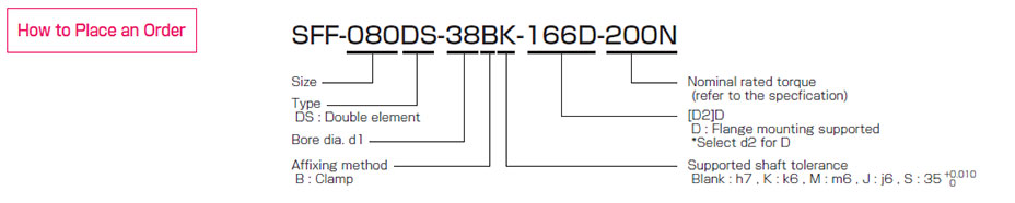
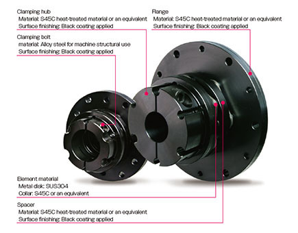
Flange mounting supportedSupports direct drive motor and speed reducer.
[Specifications]
| Model |
Rated Torque
[N・m] |
Misalignment |
Max. rotation speed
[min-1] |
Torsional stiffness
[N・m/rad] |
Axial stiffness
[N/mm] |
Moment of inertia
[kg/m2] |
Mass
[kg] |
| Parallel [mm] |
Angular [°] |
Axial [mm] |
| SFF-070DS-□B-105D-100N |
100 |
0.25 |
1(On one side) |
±1.0 |
1000 |
120000 |
242 |
1.20×10⁻³ |
1.08 |
| SFF-080DS-□B-166D-200N |
200 |
0.31 |
1(On one side) |
±1.0 |
1000 |
155000 |
273 |
8.35×10⁻³ |
3.11 |
| SFF-090DS-□B-166D-300N |
300 |
0.32 |
1(On one side) |
±1.2 |
1000 |
260000 |
160.5 |
8.69×10⁻³ |
3.18 |
| SFF-100DS-□B-166D-450N |
450 |
0.38 |
1(On one side) |
±1.3 |
1000 |
370000 |
270 |
10.01×10⁻³ |
3.91 |
| SFF-120DS-□B-166D-600N |
600 |
0.38 |
1(On one side) |
±1.6 |
1000 |
485000 |
180 |
12.66×10⁻³ |
4.57 |
* Max. rotation speed does not take into account dynamic balance.
* Torsional stiffness values given are measured values for the element alone.
* The moment of inertia and mass are measured for the maximum bore diameter.
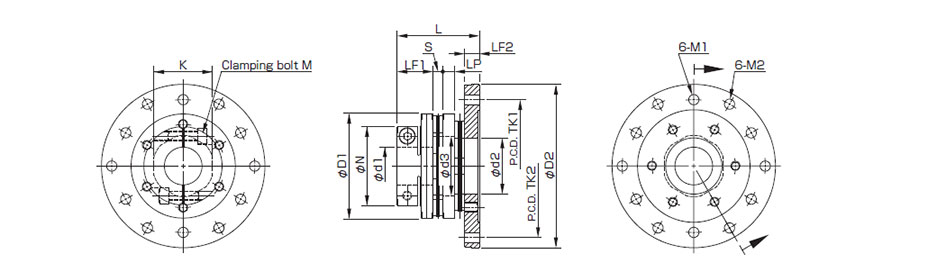
[Dimensions]
| Model |
d1
[mm] |
d2
[mm] |
D1
[mm] |
D2
[mm] |
L
[mm] |
N
[mm] |
LF1
[mm] |
LF2
[mm] |
LP
[mm] |
S
[mm] |
d3
[mm] |
K
[mm] |
M1
[mm] |
TK1
[mm] |
M2
[mm] |
TK2
[mm] |
M
Qty - nominal dia |
M Tightening
torque [N・m] |
| SFF-070DS-□B-105D-100N |
28~35 |
36 |
68 |
105 |
54.8 |
56 |
25 |
10 |
8 |
5.9 |
37 |
38 |
6.4 |
86 |
6.4 |
92 |
2-M6 |
14 |
| SFF-080DS-□B-166D-200N |
28~38 |
39 |
78 |
166 |
68.9 |
70(74) |
30 |
13.5 |
10 |
7.7 |
40 |
42 |
6.4 |
150 |
8.6 |
150 |
2-M8 |
34 |
| SFF-090DS-□B-166D-300N |
35~42 |
49 |
88 |
166 |
70.1 |
74 |
30 |
13.5 |
10 |
8.3 |
50 |
50 |
6.4 |
150 |
8.6 |
150 |
2-M8 |
34 |
| SFF-100DS-□B-166D-450N |
32~48 |
51 |
98 |
166 |
85.9 |
84 |
40 |
13.5 |
12 |
10.2 |
52 |
56 |
6.4 |
150 |
8.6 |
150 |
2-M10 |
68 |
| SFF-120DS-□B-166D-600N |
48~55 |
67 |
118 |
166 |
85.9 |
100 |
40 |
13.5 |
12 |
10.2 |
72 |
68 |
6.4 |
150 |
8.6 |
150 |
2-M10 |
68 |
* The figures in parentheses ( ) for the SFF-080 are the values when d1 is φ38 mm.
* Special arrangements may be possible for mounting holes at the flange end regarding bore diameter, number, and pitch. Check if arrangements are possible.
[Standard bore diameter]
| Model |
Standard bore diameter d1 [mm] |
| 28 |
30 |
32 |
35 |
38 |
40 |
42 |
45 |
48 |
50 |
55 |
| SFF-070DS-□B-105D-100N |
● |
● |
● |
● |
|
|
|
|
|
|
|
| SFF-080DS-□B-166D-200N |
● |
● |
● |
● |
● |
|
|
|
|
|
|
| SFF-090DS-□B-166D-300N |
|
|
|
● |
● |
● |
● |
|
|
|
|
| SFF-100DS-□B-166D-450N |
|
|
● |
● |
● |
● |
● |
● |
● |
|
|
| SFF-120DS-□B-166D-600N |
|
|
|
|
|
|
|
|
● |
● |
● |
* The bore diameters marked with ● are supported as standard bore diameter.
Clean room compatible Single elementIt is a clean room compatible product that has been cleaned, assembled (ISO class 6) and packed in consideration of its use in clean rooms.
[Specifications]
| Model |
Rated Torque
[N・m] |
Misalignment |
Max. rotation speed
[min-1] |
Torsional stiffness
[N・m/rad] |
Axial stiffness
[N/mm] |
Moment of inertia
[kg/m2] |
Mass
[kg] |
| Parallel [mm] |
Angular [°] |
Axial [mm] |
| SFF-040SS-□-□B-□B-8N |
8 |
0.02 |
1 |
±0.2 |
18000 |
15000 |
174 |
0.03×10 -3 |
0.17 |
| SFF-050SS-□-□B-□B-16N |
16 |
0.02 |
1 |
±0.3 |
18000 |
32000 |
145 |
0.10×10 -3 |
0.36 |
| SFF-060SS-□-□B-□B-40N |
40 |
0.02 |
1 |
±0.3 |
18000 |
104000 |
399 |
0.22×10 -3 |
0.52 |
| SFF-060SS-□-□B-□B-50N |
50 |
0.02 |
1 |
±0.3 |
18000 |
104000 |
399 |
0.23×10 -3 |
0.49 |
| SFF-070SS-□-□B-□B-65N |
65 |
0.02 |
1 |
±0.5 |
18000 |
240000 |
484 |
0.40×10 -3 |
0.72 |
| SFF-080SS-□-□B-□B-120N |
120 |
0.02 |
1 |
±0.5 |
17000 |
310000 |
546 |
1.25×10 -3 |
1.40 |
| SFF-090SS-□-□B-□B-150N |
150 |
0.02 |
1 |
±0.6 |
15000 |
520000 |
321 |
1.58×10⁻³ |
1.53 |
| SFF-100SS-□-□B-□B-250N |
250 |
0.02 |
1 |
±0.65 |
13000 |
740000 |
540 |
3.27×10⁻³ |
2.53 |
* Max. rotation speed does not take into account dynamic balance.
* Torsional stiffness values given are measured values for the element alone.
* The moment of inertia and mass are measured for the maximum bore diameter.
[Dimensions]
| Model |
d1
[mm] |
d2
[mm] |
D
[mm] |
L
[mm] |
N1・N2
[mm] |
LF
[mm] |
S
[mm] |
K
[mm] |
M1・M2
Qty - nominal dia |
Tightening torque [N・m] |
| CC Low dust |
CF Fluorine |
| SFF-040SS-□-□B-□B-8N |
8~16 |
8~16 |
38 |
38.9 |
33 |
17.5 |
3.9 |
17 |
2-M4 |
4.5 |
4.5 |
| SFF-050SS-□-□B-□B-16N |
10~19 |
10~19 |
48 |
48.4 |
42 |
21.5 |
5.4 |
20 |
2-M5 |
9 |
8.5 |
| SFF-060SS-□-□B-□B-40N |
12~22 |
12~22 |
58 |
53.4 |
44 |
24 |
5.4 |
32 |
2-M6 |
16 |
16 |
| - |
24~28 |
58 |
53.4 |
48 |
24 |
5.4 |
32 |
2-M5 |
9 |
8.5 |
| - |
30 |
58 |
53.4 |
52 |
24 |
5.4 |
32 |
2-M5 |
9 |
8.5 |
| SFF-060SS-□-□B-□B-50N |
24~28 |
24~28 |
58 |
53.4 |
48 |
24 |
5.4 |
32 |
2-M5 |
9 |
8.5 |
| 30 |
30 |
58 |
53.4 |
52 |
24 |
5.4 |
32 |
2-M5 |
9 |
8.5 |
| SFF-070SS-□-□B-□B-65N |
18~19 |
18~25 |
68 |
55.9 |
47 |
25 |
5.9 |
38 |
2-M6 |
16 |
16 |
| - |
28~35 |
68 |
55.9 |
56 |
25 |
5.9 |
38 |
2-M6 |
16 |
16 |
| SFF-080SS-□-□B-□B-120N |
28~35 |
28~35 |
78 |
67.7 |
70 |
30 |
7.7 |
42 |
2-M8 |
37 |
45 |
| 38 |
38 |
78 |
67.7 |
74 |
30 |
7.7 |
42 |
2-M8 |
37 |
45 |
| SFF-090SS-□-□B-□B-150N |
35~42 |
35~42 |
88 |
68.3 |
74 |
30 |
8.3 |
50 |
2-M8 |
37 |
45 |
| SFF-100SS-□-□B-□B-250N |
38~48 |
38~48 |
98 |
90.2 |
84 |
40 |
10.2 |
56 |
2-M10 |
68 |
65 |
* Nominal diameter of clamping bolt M1/M2 is given as number of bolts - nominal diameter, and the number is the number for one hub.
* You can choose from two types of grease for clamp bolts : low dust generation grease and fluorine grease.
[Standard bore diameter]
| Model |
Standard bore diameter d1・d2 [mm] |
| 8 |
9 |
9.525 |
10 |
11 |
12 |
14 |
15 |
16 |
17 |
18 |
19 |
20 |
22 |
24 |
25 |
28 |
30 |
32 |
35 |
38 |
40 |
42 |
45 |
48 |
| SFF-040SS-□-□B-□B-8N |
● |
● |
● |
● |
● |
● |
● |
● |
● |
|
|
|
|
|
|
|
|
|
|
|
|
|
|
|
|
| SFF-050SS-□-□B-□B-16N |
|
|
|
● |
● |
● |
● |
● |
● |
● |
● |
● |
|
|
|
|
|
|
|
|
|
|
|
|
|
| SFF-060SS-□-□B-□B-40N |
|
|
|
|
|
● |
● |
● |
● |
● |
● |
● |
● |
● |
● |
● |
● |
● |
|
|
|
|
|
|
|
| SFF-060SS-□-□B-□B-50N |
|
|
|
|
|
|
|
|
|
|
|
|
|
|
● |
● |
● |
● |
|
|
|
|
|
|
|
| SFF-070SS-□-□B-□B-65N |
|
|
|
|
|
|
|
|
|
|
● |
● |
● |
● |
● |
● |
● |
● |
● |
● |
|
|
|
|
|
| SFF-080SS-□-□B-□B-120N |
|
|
|
|
|
|
|
|
|
|
|
|
|
|
|
|
● |
● |
● |
● |
● |
|
|
|
|
| SFF-090SS-□-□B-□B-150N |
|
|
|
|
|
|
|
|
|
|
|
|
|
|
|
|
|
|
|
● |
● |
● |
● |
|
|
| SFF-100SS-□-□B-□B-250N |
|
|
|
|
|
|
|
|
|
|
|
|
|
|
|
|
|
|
|
|
● |
● |
● |
● |
● |
* The bore diameters marked with ● are supported as standard bore diameter.
Clean room compatible Double elementIt is a clean room compatible product that has been cleaned, assembled (ISO class 6) and packed in consideration of its use in clean rooms.
[Specifications]
| Model |
Rated Torque
[N・m] |
Misalignment |
Max. rotation speed
[min-1] |
Torsional stiffness
[N・m/rad] |
Axial stiffness
[N/mm] |
Moment of inertia
[kg/m2] |
Mass
[kg] |
| Parallel [mm] |
Angular [°] |
Axial [mm] |
| SFF-040DS-□-□B-□B-8N |
8 |
0.1 |
1(On one side) |
±0.4 |
14000 |
7500 |
87 |
0.04×10 -3 |
0.22 |
| SFF-050DS-□-□B-□B-16N |
16 |
0.2 |
1(On one side) |
±0.6 |
14000 |
16000 |
72.5 |
0.13×10 -3 |
0.46 |
| SFF-060DS-□-□B-□B-40N |
40 |
0.2 |
1(On one side) |
±0.6 |
14000 |
52000 |
199.5 |
0.28×10 -3 |
0.64 |
| SFF-060DS-□-□B-□B-50N |
50 |
0.2 |
1(On one side) |
±0.6 |
14000 |
52000 |
199.5 |
0.29×10 -3 |
0.61 |
| SFF-070DS-□-□B-□B-65N |
65 |
0.25 |
1(On one side) |
±1.0 |
14000 |
120000 |
242 |
0.53×10 -3 |
0.90 |
| SFF-080DS-□-□B-□B-120N |
120 |
0.31 |
1(On one side) |
±1.0 |
13000 |
155000 |
273 |
1.50×10⁻³ |
1.72 |
| SFF-090DS-□-□B-□B-150N |
150 |
0.32 |
1(On one side) |
±1.2 |
12000 |
260000 |
160.5 |
2.03×10⁻³ |
2.02 |
| SFF-100DS-□-□B-□B-250N |
250 |
0.38 |
1(On one side) |
±1.3 |
10000 |
370000 |
270 |
4.18×10⁻³ |
3.12 |
* Max. rotation speed does not take into account dynamic balance.
* Torsional stiffness values given are measured values for the element alone.
* The moment of inertia and mass are measured for the maximum bore diameter.
[Dimensions]
| Model |
d1
[mm] |
d2
[mm] |
D
[mm] |
L
[mm] |
N1・N2
[mm] |
LF
[mm] |
LP
[mm] |
S
[mm] |
d3
[mm] |
K
[mm] |
M1・M2
Qty - nominal dia |
Tightening torque [N・m] |
| CC Low dust |
CF Fluorine |
| SFF-040DS-□-□B-□B-8N |
8~16 |
8~16 |
38 |
48.8 |
33 |
17.5 |
6 |
3.9 |
17 |
17 |
2-M4 |
4.5 |
4.5 |
| SFF-050DS-□-□B-□B-16N |
10~19 |
10~19 |
48 |
60.8 |
42 |
21.5 |
7 |
5.4 |
20 |
20 |
2-M5 |
9 |
8.5 |
| SFF-060DS-□-□B-□B-40N |
12~22 |
12~22 |
58 |
65.8 |
44 |
24 |
7 |
5.4 |
31 |
32 |
2-M6 |
16 |
16 |
| - |
24~28 |
58 |
65.8 |
48 |
24 |
7 |
5.4 |
31 |
32 |
2-M5 |
9 |
8.5 |
| - |
30 |
58 |
65.8 |
52 |
24 |
7 |
5.4 |
31 |
32 |
2-M5 |
9 |
8.5 |
| SFF-060DS-□-□B-□B-50N |
24~28 |
24~28 |
58 |
65.8 |
48 |
24 |
7 |
5.4 |
31 |
32 |
2-M5 |
9 |
8.5 |
| 30 |
30 |
58 |
68.5 |
52 |
24 |
7 |
5.4 |
31 |
32 |
2-M5 |
9 |
8.5 |
| SFF-070DS-□-□B-□B-65N |
18~19 |
18~25 |
68 |
69.8 |
47 |
25 |
8 |
5.9 |
37 |
38 |
2-M6 |
16 |
16 |
| - |
28~35 |
68 |
69.8 |
56 |
25 |
8 |
5.9 |
37 |
38 |
2-M6 |
16 |
16 |
| SFF-080DS-□-□B-□B-120N |
28~35 |
28~35 |
78 |
85.4 |
70 |
30 |
10 |
7.7 |
40 |
42 |
2-M8 |
37 |
45 |
| 38 |
38 |
78 |
85.4 |
74 |
30 |
10 |
7.7 |
40 |
42 |
2-M8 |
37 |
45 |
| SFF-090DS-□-□B-□B-150N |
35~42 |
35~42 |
88 |
86.6 |
74 |
30 |
10 |
8.3 |
50 |
50 |
2-M8 |
37 |
45 |
| SFF-100DS-□-□B-□B-250N |
38~48 |
38~48 |
98 |
112.4 |
84 |
40 |
12 |
10.2 |
52 |
56 |
2-M10 |
68 |
65 |
* Nominal diameter of clamping bolt M1/M2 is given as number of bolts - nominal diameter, and the number is the number for one hub.
* You can choose from two types of grease for clamp bolts : low dust generation grease and fluorine grease.
[Standard bore diameter]
| Model |
Standard bore diameter d1・d2 [mm] |
| 8 |
9 |
9.525 |
10 |
11 |
12 |
14 |
15 |
16 |
17 |
18 |
19 |
20 |
22 |
24 |
25 |
28 |
30 |
32 |
35 |
38 |
40 |
42 |
45 |
48 |
| SFF-040DS-□-□B-□B-8N |
● |
● |
● |
● |
● |
● |
● |
● |
● |
|
|
|
|
|
|
|
|
|
|
|
|
|
|
|
|
| SFF-050DS-□-□B-□B-16N |
|
|
|
● |
● |
● |
● |
● |
● |
● |
● |
● |
|
|
|
|
|
|
|
|
|
|
|
|
|
| SFF-060DS-□-□B-□B-40N |
|
|
|
|
|
● |
● |
● |
● |
● |
● |
● |
● |
● |
● |
● |
● |
● |
|
|
|
|
|
|
|
| SFF-060DS-□-□B-□B-50N |
|
|
|
|
|
|
|
|
|
|
|
|
|
|
● |
● |
● |
● |
|
|
|
|
|
|
|
| SFF-070DS-□-□B-□B-65N |
|
|
|
|
|
|
|
|
|
|
● |
● |
● |
● |
● |
● |
● |
● |
● |
● |
|
|
|
|
|
| SFF-080DS-□-□B-□B-120N |
|
|
|
|
|
|
|
|
|
|
|
|
|
|
|
|
● |
● |
● |
● |
● |
|
|
|
|
| SFF-090DS-□-□B-□B-150N |
|
|
|
|
|
|
|
|
|
|
|
|
|
|
|
|
|
|
|
● |
● |
● |
● |
|
|
| SFF-100DS-□-□B-□B-250N |
|
|
|
|
|
|
|
|
|
|
|
|
|
|
|
|
|
|
|
|
● |
● |
● |
● |
● |
* The bore diameters marked with ● are supported as standard bore diameter.
 日本語
日本語 English
 Deutsch
 中文
中文 한국어
한국어