日本語
日本語 English
 Deutsch
 中文
中文 한국어
한국어


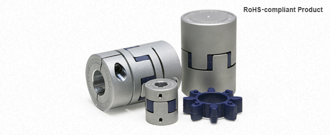
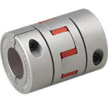
ALS (B) Type

![]()
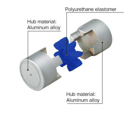
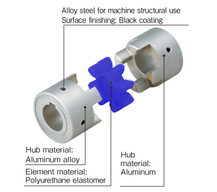
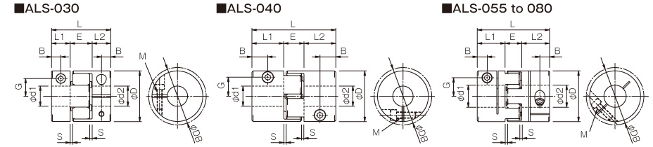
ALS (B) Types (key/set screw type)
[Specifications]
| Model | Torque | Misalignment | Max. rotation speed [min-1] | Static torsional stiffness [N・m/rad] | Radial stiffness [N/mm] | Moment of inertia [kg・m2] | Mass [kg] | |||
|---|---|---|---|---|---|---|---|---|---|---|
| Nominal [N・m] | Max. [N・m] | Parallel [mm] | Angular [°] | Axial [mm] | ||||||
| ALS-030-B | 12.5 | 25 | 0.17 | 1 | -0.2 to +1.0 | 15900 | 90 | 460 | 6.13×10⁻⁶ | 0.045 |
| ALS-040-B | 17 | 34 | 0.20 | 1 | -0.5 to +1.2 | 11900 | 400 | 640 | 3.86×10⁻⁵ | 0.15 |
| ALS-055-B | 60 | 120 | 0.22 | 1 | -0.2 to +1.4 | 8700 | 1150 | 400 | 1.66×10⁻⁴ | 0.35 |
| ALS-065-B | 160 | 320 | 0.25 | 1 | -0.6 to +1.5 | 7400 | 2000 | 800 | 3.57×10⁻⁴ | 0.51 |
| ALS-080-B | 325 | 650 | 0.28 | 1 | -0.9 to +1.8 | 6000 | 4550 | 600 | 1.06×10⁻³ | 1.01 |
| ALS-095-B | 450 | 900 | 0.32 | 1 | -0.5 to +2.0 | 5000 | 12000 | 800 | 2.22×10⁻³ | 1.48 |
| ALS-105-B | 525 | 1050 | 0.36 | 1 | -0.9 to +2.0 | 4500 | 15000 | 2000 | 3.70×10⁻³ | 2.02 |
*Max. rotation speed does not take into account dynamic balance.
*Stiffness values given are from measurements taken at 20℃.
*The moment of inertia and mass are measured for the maximum bore diameter.
[Dimensions]
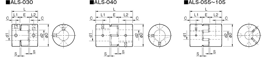
| Model | d1, d2 | D | L | L1, L2 | E | S | C | ||
|---|---|---|---|---|---|---|---|---|---|
| Pilot bore | Min. | Max. | |||||||
| ALS-030-B | 5 | 6 | 14 | 30 | 35 | 11 | 13 | 1.5 | 5.5 |
| ALS-040-B | 5 | 8 | 22 | 40 | 66 | 25 | 16 | 2 | 12.5 |
| ALS-055-B | 5 | 10 | 28 | 55 | 78 | 30 | 18 | 2 | 15 |
| ALS-065-B | 5 | 14 | 38 | 65 | 90 | 35 | 20 | 2.5 | 17.5 |
| ALS-080-B | 10 | 19 | 45 | 80 | 114 | 45 | 24 | 3 | 22.5 |
| ALS-095-B | 8 | 19 | 55 | 95 | 126 | 50 | 26 | 3 | 25 |
| ALS-105-B | 10 | 19 | 60 | 105 | 140 | 56 | 28 | 3.5 | 28 |
*"Pilot bore" refers to center processing.
[Standard bore diameter]
| Model | Standard bore diameter d1, d2 [mm] | |||||||||||||||||||||||||||||||
|---|---|---|---|---|---|---|---|---|---|---|---|---|---|---|---|---|---|---|---|---|---|---|---|---|---|---|---|---|---|---|---|---|
| 6 | 6.35 | 7 | 8 | 9 | 9.525 | 10 | 11 | 12 | 14 | 15 | 16 | 17 | 18 | 19 | 20 | 22 | 24 | 25 | 28 | 30 | 32 | 35 | 38 | 40 | 42 | 45 | 48 | 50 | 55 | 56 | 60 | |
| ALS-030-B | ● | ● | ● | ● | ● | ● | ● | ● | ● | ● | ||||||||||||||||||||||
| ALS-040-B | ● | ● | ● | ● | ● | ● | ● | ● | ● | ● | ● | ● | ● | ● | ||||||||||||||||||
| ALS-055-B | ● | ● | ● | ● | ● | ● | ● | ● | ● | ● | ● | ● | ● | ● | ||||||||||||||||||
| ALS-065-B | ● | ● | ● | ● | ● | ● | ● | ● | ● | ● | ● | ● | ● | ● | ● | |||||||||||||||||
| ALS-080-B | ● | ● | ● | ● | ● | ● | ● | ● | ● | ● | ● | ● | ● | |||||||||||||||||||
| ALS-095-B | ● | ● | ● | ● | ● | ● | ● | ● | ● | ● | ● | ● | ● | ● | ● | ● | ||||||||||||||||
| ALS-105-B | ● | ● | ● | ● | ● | ● | ● | ● | ● | ● | ● | ● | ● | ● | ● | ● | ● | ● | ||||||||||||||
*The bore diameters marked with ● are supported as standard bore diameter.
*ø11 and below have no keyway; ø12 and above can be processed for old JIS standards, new JIS standards, and new standard motors.
[Element]
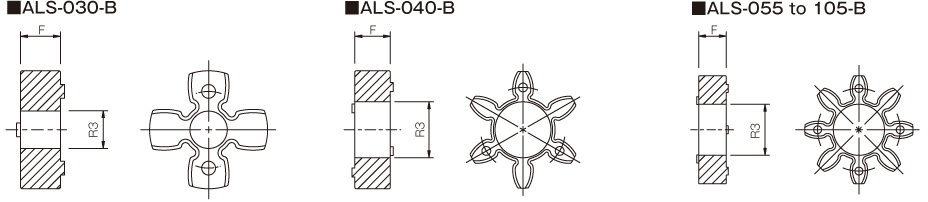
| Model | F | R3 |
|---|---|---|
| ALS-030-B-EL | 10.2 | 10.5 |
| ALS-040-B-EL | 12 | 18.5 |
| ALS-055-B-EL | 14 | 27.5 |
| ALS-065-B-EL | 15 | 32 |
| ALS-080-B-EL | 18 | 41 |
| ALS-095-B-EL | 20 | 47 |
| ALS-105-B-EL | 21 | 50 |

[Standard Hole-drilling Standards]
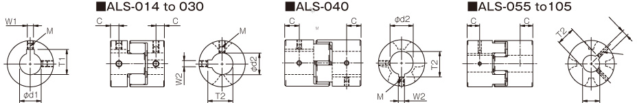
| Models compliant with the old JIS standard (class 2) JIS B 1301 1959 | Models compliant with the new JIS standard (H9) JIS B 1301 1996 | Models compliant with the new JIS standard (JS9) JIS B 1301 1996 | Models compliant with the motor standard JIS C 4210 2001 | ||||||||||||||||
|---|---|---|---|---|---|---|---|---|---|---|---|---|---|---|---|---|---|---|---|
| Nominal bore diameter | Bore diameter [d1・d2] | Keyway width [W1・W2] | Keyway height [T1・T2] | Set screw hole [M] | Nominal bore diameter | Bore diameter [d1・d2] | Keyway width [W1・W2] | Keyway height [T1・T2] | Set screw hole [M] | Nominal bore diameter | Bore diameter [d1・d2] | Keyway width [W1・W2] | Keyway height [T1・T2] | Set screw hole [M] | Nominal bore diameter | Bore diameter [d1・d2] | Keyway width [W1・W2] | Keyway height [T1・T2] | Set screw hole [M] |
| Tolerance H7,H8 | Tolerance E9 | - | - | Tolerance H7 | Tolerance H9 | - | - | Tolerance H7 | Tolerance JS9 | - | - | Tolerance G7,F7 | Tolerance H9 | - | - | ||||
| 3 | 3+0.0180 | - | - | 1-M3 | - | - | - | - | - | - | - | - | - | - | - | - | - | - | - |
| 4 | 4+0.0180 | - | - | 2-M3 | - | - | - | - | - | - | - | - | - | - | - | - | - | - | - |
| 5 | 5+0.0180 | - | - | 2-M3 | - | - | - | - | - | - | - | - | - | - | - | - | - | - | - |
| 6 | 6+0.0180 | - | - | 2-M4 | - | - | - | - | - | - | - | - | - | - | - | - | - | - | - |
| 6.35 | 6.35+0.0220 | - | - | 2-M4 | - | - | - | - | - | - | - | - | - | - | - | - | - | - | - |
| 7 | 7+0.0220 | - | - | 2-M4 | - | - | - | - | - | - | - | - | - | - | - | - | - | - | - |
| 8 | 8+0.0220 | - | - | 2-M4 | - | - | - | - | - | - | - | - | - | - | - | - | - | - | - |
| 9 | 9+0.0220 | - | - | 2-M4 | - | - | - | - | - | - | - | - | - | - | - | - | - | - | - |
| 9.525 | 9.525+0.0220 | - | - | 2-M4 | - | - | - | - | - | - | - | - | - | - | - | - | - | - | - |
| 10 | 10+0.0220 | - | - | 2-M4 | - | - | - | - | - | - | - | - | - | - | - | - | - | - | - |
| 11 | 11+0.0180 | - | - | 2-M4 | - | - | - | - | - | - | - | - | - | - | - | - | - | - | - |
| 12 | 12+0.0180 | 4+0.050+0.020 | 13.5+0.30 | 2-M4 | 12H | 12+0.0180 | 4+0.0300 | 13.8+0.30 | 2-M4 | 12J | 12+0.0180 | 4±0.0150 | 13.8+0.30 | 2-M4 | - | - | - | - | - |
| 14 | 14+0.0180 | 5+0.050+0.020 | 16.0+0.30 | 2-M4 | 14H | 14+0.0180 | 5+0.0300 | 16.3+0.30 | 2-M4 | 14J | 14+0.0180 | 5±0.0150 | 16.3+0.30 | 2-M4 | 14N | 14+0.024+0.006 | 5+0.0300 | 16.3+0.30 | 2-M4 |
| 15 | 15+0.0180 | 5+0.050+0.020 | 17.0+0.30 | 2-M4 | 15H | 15+0.0180 | 5+0.0300 | 17.3+0.30 | 2-M4 | 15J | 15+0.0180 | 5±0.0150 | 17.3+0.30 | 2-M4 | - | - | - | - | - |
| 16 | 16+0.0180 | 5+0.050+0.020 | 18.0+0.30 | 2-M4 | 16H | 16+0.0180 | 5+0.0300 | 18.3+0.30 | 2-M4 | 16J | 16+0.0180 | 5±0.0150 | 18.3+0.30 | 2-M4 | - | - | - | - | - |
| 17 | 17+0.0180 | 5+0.050+0.020 | 19.0+0.30 | 2-M4 | 17H | 17+0.0180 | 5+0.0300 | 19.3+0.30 | 2-M4 | 17J | 17+0.0180 | 5±0.0150 | 19.3+0.30 | 2-M4 | - | - | - | - | - |
| 18 | 18+0.0180 | 5+0.050+0.020 | 20.0+0.30 | 2-M4 | 18H | 18+0.0180 | 6+0.0300 | 20.8+0.30 | 2-M5 | 18J | 18+0.0180 | 6±0.0150 | 20.8+0.30 | 2-M5 | - | - | - | - | - |
| 19 | 19+0.0210 | 5+0.050+0.020 | 21.0+0.30 | 2-M4 | 19H | 19+0.0210 | 6+0.0300 | 21.8+0.30 | 2-M5 | 19J | 19+0.0210 | 6±0.0150 | 21.8+0.30 | 2-M5 | 19N | 19+0.028+0.007 | 6+0.0300 | 21.8+0.30 | 2-M5 |
| 20 | 20+0.0210 | 5+0.050+0.020 | 22.0+0.30 | 2-M4 | 20H | 20+0.0210 | 6+0.0300 | 22.8+0.30 | 2-M5 | 20J | 20+0.0210 | 6±0.0150 | 22.8+0.30 | 2-M5 | - | - | - | - | - |
| 22 | 22+0.0210 | 7+0.061+0.025 | 25.0+0.30 | 2-M6 | 22H | 22+0.0210 | 6+0.0300 | 24.8+0.30 | 2-M5 | 22J | 22+0.0210 | 6±0.0150 | 24.8+0.30 | 2-M5 | - | - | - | - | - |
| 24 | 24+0.0210 | 7+0.061+0.025 | 27.0+0.30 | 2-M6 | 24H | 24+0.0210 | 8+0.0360 | 27.3+0.30 | 2-M6 | 24J | 24+0.0210 | 8±0.0180 | 27.3+0.30 | 2-M6 | 24N | 24+0.028+0.007 | 8+0.0360 | 27.3+0.30 | 2-M6 |
| 25 | 25+0.0210 | 7+0.061+0.025 | 28.0+0.30 | 2-M6 | 25H | 25+0.0210 | 8+0.0360 | 28.3+0.30 | 2-M6 | 25J | 25+0.0210 | 8±0.0180 | 28.3+0.30 | 2-M6 | - | - | - | - | - |
| 28 | 28+0.0210 | 7+0.061+0.025 | 31.0+0.30 | 2-M6 | 28H | 28+0.0210 | 8+0.0360 | 31.3+0.30 | 2-M6 | 28J | 28+0.0210 | 8±0.0180 | 31.3+0.30 | 2-M6 | 28N | 28+0.028+0.007 | 8+0.0360 | 31.3+0.30 | 2-M6 |
| 30 | 30+0.0210 | 7+0.061+0.025 | 33.0+0.30 | 2-M6 | 30H | 30+0.0210 | 8+0.0360 | 33.3+0.30 | 2-M6 | 30J | 30+0.0210 | 8±0.0180 | 33.3+0.30 | 2-M6 | - | - | - | - | - |
| 32 | 32+0.0250 | 10+0.061+0.025 | 35.5+0.30 | 2-M8 | 32H | 32+0.0250 | 10+0.0360 | 35.3+0.30 | 2-M8 | 32J | 32+0.0250 | 10±0.0180 | 35.3+0.30 | 2-M8 | - | - | - | - | - |
| 35 | 35+0.0250 | 10+0.061+0.025 | 38.5+0.30 | 2-M8 | 35H | 35+0.0250 | 10+0.0360 | 38.3+0.30 | 2-M8 | 35J | 35+0.0250 | 10±0.0180 | 38.3+0.30 | 2-M8 | - | - | - | - | - |
| 38 | 38+0.0250 | 10+0.061+0.025 | 41.5+0.30 | 2-M8 | 38H | 38+0.0250 | 10+0.0360 | 41.3+0.30 | 2-M8 | 38J | 38+0.0250 | 10±0.0180 | 41.3+0.30 | 2-M8 | 38N | 38+0.050+0.025 | 10+0.0360 | 41.3+0.30 | 2-M8 |
| 40 | 40+0.0250 | 10+0.061+0.025 | 43.5+0.30 | 2-M8 | 40H | 40+0.0250 | 12+0.0430 | 43.3+0.30 | 2-M8 | 40J | 40+0.0250 | 12±0.0215 | 43.3+0.30 | 2-M8 | - | - | - | - | - |
| 42 | 42+0.0250 | 12+0.075+0.032 | 45.5+0.30 | 2-M8 | 42H | 42+0.0250 | 12+0.0430 | 45.3+0.30 | 2-M8 | 42J | 42+0.0250 | 12±0.0215 | 45.3+0.30 | 2-M8 | 42N | 42+0.050+0.025 | 12+0.0430 | 45.3+0.30 | 2-M8 |
| 45 | 45+0.0250 | 12+0.075+0.032 | 48.5+0.30 | 2-M8 | 45H | 45+0.0250 | 14+0.0430 | 48.8+0.30 | 2-M10 | 45J | 45+0.0250 | 14±0.0215 | 48.8+0.30 | 2-M10 | - | - | - | - | - |
| 48 | 48+0.0250 | 12+0.075+0.032 | 51.5+0.30 | 2-M8 | 48H | 48+0.0250 | 14+0.0430 | 51.8+0.30 | 2-M10 | 48J | 48+0.0250 | 14±0.0215 | 51.8+0.30 | 2-M10 | 48N | 48+0.050+0.025 | 14+0.0430 | 51.8+0.30 | 2-M10 |
| 50 | 50+0.0250 | 12+0.075+0.032 | 53.5+0.30 | 2-M8 | 50H | 50+0.0250 | 14+0.0430 | 53.8+0.30 | 2-M10 | 50J | 50+0.0250 | 14±0.0215 | 53.8+0.30 | 2-M10 | - | - | - | - | - |
| 55 | 55+0.0300 | 15+0.075+0.032 | 60.0+0.30 | 2-M10 | 55H | 55+0.0300 | 16+0.0430 | 59.3+0.30 | 2-M10 | 55J | 55+0.0300 | 16±0.0215 | 59.3+0.30 | 2-M10 | 55N | 55+0.060+0.030 | 16+0.0430 | 59.3+0.30 | 2-M10 |
| 56 | 56+0.0300 | 15+0.075+0.032 | 61.0+0.30 | 2-M10 | 56H | 56+0.0300 | 16+0.0430 | 60.3+0.30 | 2-M10 | 56J | 56+0.0300 | 16±0.0215 | 60.3+0.30 | 2-M10 | - | - | - | - | - |
| 60 | 60+0.0300 | 15+0.075+0.032 | 65.0+0.30 | 2-M10 | 60H | 60+0.0300 | 18+0.0430 | 64.4+0.30 | 2-M10 | 60J | 60+0.0300 | 18±0.0215 | 64.4+0.30 | 2-M10 | 60N | 60+0.060+0.030 | 18+0.0430 | 64.4+0.30 | 2-M10 |
*All standards starting from ø11 are the same as those in the old JIS standards column.
*For ALS-014, set screw size is M3.
*Positions of set screws and keyways are not on the same plane.
*Set screws are included with the product.
*Positioning precision for keyway milling is determined by sight.
*Contact Miki Pulley when the keyway requires a positioning precision for a particular flange hub.
*Consult the technical documentation at the end of this volume for standard dimensions for bore drilling other than those given here.
[Set screw position]
| Model | Distance C from edge[mm] |
|---|---|
| ALS-014 | 3.5 |
| ALS-020 | 5 |
| ALS-030 | 5.5 |
| ALS-040 | 12.5 |
| ALS-055 | 15 |
| ALS-065 | 17.5 |
| ALS-080 | 22.5 |
| ALS-095 | 25 |
| ALS-105 | 28 |
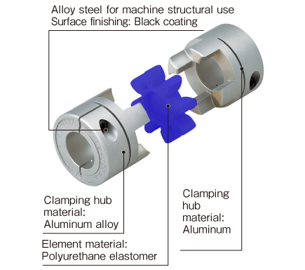
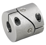
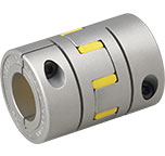
ALS (B) Types (clamp types)
[Specifications]
| Model | Misalignment | Max. rotation speed [min-1] | Static torsional stiffness [N・m/rad] | Radial stiffness [N/mm] | Moment of inertia [kg・m2] | Mass [kg] | ||
|---|---|---|---|---|---|---|---|---|
| Parallel [mm] | Angular [°] | Axial [mm] | ||||||
| ALS-030-B | 0.17 | 1 | -0.2 to +1.0 | 10000 | 90 | 460 | 6.07×10⁻⁶ | 0.043 |
| ALS-040-B | 0.2 | 1 | -0.5 to +1.2 | 10000 | 400 | 640 | 4.00×10⁻⁵ | 0.16 |
| ALS-055-B | 0.22 | 1 | -0.2 to +1.4 | 7000 | 1,150 | 400 | 1.63×10⁻⁴ | 0.34 |
| ALS-065-B | 0.25 | 1 | -0.6 to +1.5 | 5900 | 2,000 | 800 | 3.69×10⁻⁴ | 0.54 |
| ALS-080-B | 0.28 | 1 | -0.9 to +1.8 | 4800 | 4,550 | 600 | 1.04×10⁻³ | 1.00 |
*Max. rotation speed does not take into account dynamic balance.
*Stiffness values given are from measurements taken at 20℃.
*The moment of inertia and mass are measured for the maximum bore diameter.
[Dimensions]
| Model | d1, d2 | D | DB | L | L1, L2 | E | S | B | G | M | Tightening torque [N・m] | |
|---|---|---|---|---|---|---|---|---|---|---|---|---|
| Min. | Max. | |||||||||||
| ALS-030-B | 6 | 14 | 30 | 30 | 35 | 11 | 13 | 1.5 | 5.5 | 10.5 | 1-M3 | 1.5 |
| ALS-040-B | 8 | 20 | 40 | 43.2 | 66 | 25 | 16 | 2 | 12.5 | 15 | 1-M5 | 7 |
| ALS-055-B | 10 | 28 | 55 | 55 | 78 | 30 | 18 | 2 | 10.5 | 20 | 1-M6 | 14 |
| ALS-065-B | 14 | 35 | 65 | 69.8 | 90 | 35 | 20 | 2.5 | 11.5 | 24.5 | 1-M8 | 30 |
| ALS-080-B | 19 | 45 | 80 | 80 | 114 | 45 | 24 | 3 | 11.5 | 30 | 1-M8 | 30 |
*The øDB value is measured assuming that the head of the clamping bolt is larger than the external diameter of the hub.
*The nominal diameter for the clamping bolt M is equal to the quantity minus the nominal diameter of the screw threads, where the quantity is for a hub on one side.
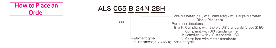
Standard bore diameter and allowable transmission torque
| Model | Standard bore diameters d1, d2 [mm] and rated transmission torque [N・m] | |||||||||||||||||||||||||
|---|---|---|---|---|---|---|---|---|---|---|---|---|---|---|---|---|---|---|---|---|---|---|---|---|---|---|
| 6 | 6.35 | 7 | 8 | 9 | 9.525 | 10 | 11 | 12 | 14 | 15 | 16 | 18 | 19 | 20 | 22 | 24 | 25 | 28 | 30 | 32 | 35 | 38 | 40 | 42 | 45 | |
| ALS-030-B | 2.0 | 2.2 | 2.7 | 3.4 | 4 | 4.4 | 4.7 | 5.4 | 6.0 | 7.4 | ||||||||||||||||
| ALS-040-B | 8 | 12 | 14 | 16 | 19 | 23 | 31 | 34 | 34 | 34 | 34 | 34 | ||||||||||||||
| ALS-055-B | 21 | 25 | 28 | 35 | 38 | 41 | 48 | 51 | 54 | 61 | 67 | 71 | 80 | |||||||||||||
| ALS-065-B | 40 | 44 | 47 | 54 | 58 | 61 | 68 | 75 | 79 | 89 | 96 | 103 | 114 | |||||||||||||
| ALS-080-B | 53 | 59 | 72 | 84 | 90 | 108 | 121 | 133 | 151 | 170 | 182 | 194 | 212 | |||||||||||||
*Bore diameters whose fields contain numbers are supported as the standard bore diameters.
*Bore diameters whose fields contain numbers are restricted in their rated transmission torque by the holding power of the shaft connection component. The numbers indicate the rated transmission torque value [N·m].
*The recommended processing tolerance for paired mounting shafts is the h7 class. However, for a bore diameter of ø35, the shaft tolerance is -0.025 to +0.010
*Bore diameters between the minimum and maximums shown in the dimensions table are compatible, but bore diameters other than those shown in the above table require other arrangements. Contact Miki Pulley for details.
[Element]
| Model | F | R3 |
|---|---|---|
| ALS-030-B-EL | 10.2 | 10.5 |
| ALS-040-B-EL | 12 | 18.5 |
| ALS-055-B-EL | 14 | 27.5 |
| ALS-065-B-EL | 15 | 32 |
| ALS-080-B-EL | 18 | 41 |
| ALS-095-B-EL | 20 | 47 |
| ALS-105-B-EL | 21 | 50 |
![]()
![]()
![]()
![]()
![]()
![]()