
SFS [G] Specified Overall Length Type

This design uses a Floating Shaft Coupling to increase the distance between shafts, replacing the double element type spacer. Because the distance between elements is greater than in the W-type spacer design, it can accommodate greater eccentricity than the single element version, which does not allow for any eccentricity. You may also specify the Specified Overall Length.
specifications
| models | Permissible (operating) torque [N·m] | Permissible Tolerance | Max. rotation speed [min⁻¹] | Torsional stiffness [N·m/rad] | Axial stiffness [N/mm] | Moment of inertia [kg·m²] | Mass [kg] | ||
|---|---|---|---|---|---|---|---|---|---|
| Eccentricity [mm] | Angular Misalignment [°] | In the axial direction [mm] | |||||||
| SFS-05G | 20 | 0.5 | 1 (one side) | ±1.2 | 20,000 | 8,000 | 21.000 | 0.20 × 10⁻³ | 0.50 |
| SFS-06G | 40 | 0.5 | 1 (one side) | ±1.6 | 16,000 | 14,000 | 22.000 | 0.55 × 10⁻³ | 0.90 |
| SFS-08G | 80 | 0.5 | 1 (one side) | ±2.0 | 13,000 | 41,000 | 30.000 | 1.50 × 10⁻³ | 1.70 |
| SFS-09G | 180 | 0.6 | 1 (per side) | ±2.4 | 12,000 | 85,000 | 61.000 | 2.90 × 10⁻³ | 2.40 |
| SFS-10G | 250 | 0.6 | 1 (per side) | ±2.8 | 10,000 | 125,000 | 80.000 | 4.60 × 10⁻³ | 3.30 |
| SFS-12G | 450 | 0.8 | 1 (per side) | ±3.2 | 8,000 | 215,000 | 98.000 | 11.80 × 10⁻³ | 5.80 |
| SFS-14G | 800 | 0.9 | 1 (per side) | ±3.6 | 7,000 | 390,000 | 156.000 | 21.20 × 10⁻³ | 8.60 |
- The max. rotation speed does not take dynamic balance into account.
- The moment of inertia and mass are the values at the maximum bore diameter.
Dimensions

| models | d1・d2 | D | N | L | LF | LS | S | F | K | M | ||
|---|---|---|---|---|---|---|---|---|---|---|---|---|
| Pilot hole | Minimum | Maximum | ||||||||||
| SFS-05G | 7 | 8 | 20 | 56 | 32 | 74 | 20 | 24 | 5 | 11 | 24 | 8-M5×22 |
| SFS-06G | 7 | 8 | 25 | 68 | 40 | 86 | 25 | 24 | 6 | 10 | 30 | 8-M6×25 |
| SFS-08G | 10 | 11 | 35 | 82 | 54 | 98 | 30 | 26 | 6 | 11 | 38 | 8-M6×29 |
| SFS-09G | 10 | 11 | 38 | 94 | 58 | 106 | 30 | 30 | 8 | 21 | 42 | 8-M8×36 |
| SFS-10G | 15 | 16 | 42 | 104 | 68 | 120 | 35 | 30 | 10 | 16 | 48 | 8-M8×36 |
| SFS-12G | 18 | 19 | 50 | 126 | 78 | 140 | 40 | 38 | 11 | 23 | 54 | 8-M10×45 |
| SFS-14G | 20 | 22 | 60 | 144 | 88 | 160 | 45 | 46 | 12 | 31 | 61 | 8-M12×54 |
- The pilot hole is a drill hole. For machined holes, please refer to the Standard hole machining specifications.
- The nominal size of a Reema Bolt M is calculated as: quantity × thread size × nominal length.
standard bore size
| models | Standard Bore Sizes: d1, d2 | |||||||||||||||||||||||||||
|---|---|---|---|---|---|---|---|---|---|---|---|---|---|---|---|---|---|---|---|---|---|---|---|---|---|---|---|---|
| 8 | 9 | 10 | 11 | 12 | 14 | 15 | 16 | 17 | 18 | 19 | 20 | 22 | 24 | 25 | 28 | 30 | 32 | 35 | 38 | 40 | 42 | 45 | 48 | 50 | 55 | 56 | 60 | |
| SFS-05G | ● | ● | ● | ● | ● | ● | ● | ● | ● | ● | ● | ● | ||||||||||||||||
| SFS-06G | ● | ● | ● | ● | ● | ● | ● | ● | ● | ● | ● | ● | ● | ● | ● | |||||||||||||
| SFS-08G | ● | ● | ● | ● | ● | ● | ● | ● | ● | ● | ● | ● | ● | ● | ● | ● | ||||||||||||
| SFS-09G | ● | ● | ● | ● | ● | ● | ● | ● | ● | ● | ● | ● | ● | ● | ● | ● | ● | |||||||||||
| SFS-10G | ● | ● | ● | ● | ● | ● | ● | ● | ● | ● | ● | ● | ● | ● | ● | |||||||||||||
| SFS-12G | ● | ● | ● | ● | ● | ● | ● | ● | ● | ● | ● | ● | ● | ● | ● | |||||||||||||
| SFS-14G | ● | ● | ● | ● | ● | ● | ● | ● | ● | ● | ● | ● | ● | ● | ● | ● | ||||||||||||
- The bore sizes in the fields marked with a ● are supported as standard bore sizes. For details, please refer to the standard hole machining specifications.

Standard Hole Machining Specifications
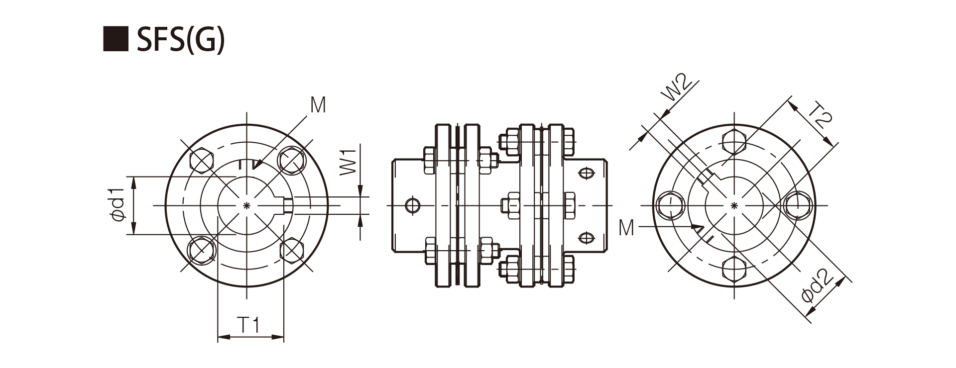
| Compliant with the former JIS Standard Type 2 (JIS B 1301, 1959) |
New JIS Standard H9 , compliant with JIS B 1301 1996 |
New JIS Standard JS9 (Compliant with JIS B 1301, 1996) |
New JIS Standard P9 : Compliant with JIS B 1301 (1996) |
Motor Standard : Compliant with JIS C 4210 (2001) |
||||||||||||||||||||
|---|---|---|---|---|---|---|---|---|---|---|---|---|---|---|---|---|---|---|---|---|---|---|---|---|
| Nominal Bore Size | Bore Size (d1, d2) |
Keyway width (W1, W2) |
Keyway height (T1, T2) |
Set screw hole (M) |
Nominal Bore Size | Bore size (d1, d2) |
Keyway width (W1, W2) |
Keyway height (T1, T2) |
Set screw hole (M) |
Nominal bore size | Bore Size (d1, d2) |
Keyway width (W1, W2) |
Keyway height (T1, T2) |
Set screw hole (M) |
Nominal bore size | Bore Size (d1, d2) |
Keyway width (W1, W2) |
Keyway height (T1, T2) |
Set screw hole (M) |
Nominal Bore Size | Bore Size (d1, d2) |
Keyway width (W1, W2) |
Keyway height (T1, T2) |
Set screw hole (M) |
| Tolerances H7, H8 | Tolerance E9 | - | - | Tolerances H7, H8 | Tolerance H9 | - | - | Tolerance H7, H8 | Tolerance JS9 | - | - | Tolerance H7, H8 | Tolerance P9 | - | - | Tolerance G7, F7 | Tolerance H9 | - | - | |||||
| 8 | 8 + 0.0220 | - | - | 2–M4 | 8H | 8+0.0220 | 3 + 0.0250 | 9.4 + 0.30 | 2-M4 | 8J | 8 + 0.0220 | 3 ± 0.0125 | 9.4 + 0.30 | 2-M4 | 8P | 8 + 0.0220 | 3–0.006–0.031 | 9.4 + 0.30 | 2-M4 | - | - | - | - | - |
| 9 | 9 + 0.0220 | - | - | 2-M4 | 9H | 9 + 0.0220 | 3 + 0.0250 | 10.4 + 0.30 | 2-M4 | 9J | 9 + 0.0220 | 3 ± 0.0125 | 10.4 + 0.30 | 2-M4 | 9P | 9 + 0.0220 | 3–0.006–0.031 | 10.4 + 0.30 | 2-M4 | - | - | - | - | - |
| 10 | 10 + 0.0220 | - | - | 2-M4 | 10H | 10 + 0.0220 | 3 + 0.0250 | 11.4 + 0.30 | 2-M4 | 10J | 10 + 0.0220 | 3 ± 0.0125 | 11.4 + 0.30 | 2-M4 | 10P | 10 + 0.0220 | 3–0.006–0.031 | 11.4 + 0.30 | 2-M4 | - | - | - | - | - |
| 11 | 11 + 0.0180 | - | - | 2-M4 | 11H | 11 + 0.0180 | 4 + 0.0300 | 12.8 + 0.30 | 2-M4 | 11J | 11 + 0.0180 | 4 ± 0.0150 | 12.8 + 0.30 | 2-M4 | 11P | 11 + 0.0180 | 4–0.012–0.042 | 12.8 + 0.30 | 2-M4 | - | - | - | - | - |
| 12 | 12 + 0.0180 | 4 + 0.050 + 0.020 | 13.5 + 0.30 | 2-M4 | 12H | 12 + 0.0180 | 4 + 0.0300 | 13.8 + 0.30 | 2-M4 | 12J | 12 + 0.0180 | 4 ± 0.0150 | 13.8 + 0.30 | 2-M4 | 12P | 12 + 0.0180 | 4–0.012–0.042 | 13.8 + 0.30 | 2-M4 | - | - | - | - | - |
| 14 | 14 + 0.0180 | 5 + 0.050 + 0.020 | 16 + 0.30 | 2-M4 | 14H | 14 + 0.0180 | 5 + 0.0300 | 16.3 + 0.30 | 2-M4 | 14J | 14 + 0.0180 | 5 ± 0.0150 | 16.3 + 0.30 | 2–M4 | 14P | 14 + 0.0180 | 5–0.012–0.042 | 16.3 + 0.30 | 2-M4 | 14N | 14 + 0.024 + 0.006 | 5 + 0.0300 | 16.3 + 0.30 | 2-M4 |
| 15 | 15 + 0.0180 | 5 + 0.050 + 0.020 | 17 + 0.30 | 2-M4 | 15H | 15 + 0.0180 | 5 + 0.0300 | 17.3 + 0.30 | 2-M4 | 15J | 15 + 0.0180 | 5 ± 0.0150 | 17.3 + 0.30 | 2-M4 | 15P | 15 + 0.0180 | 5–0.012–0.042 | 17.3 + 0.30 | 2-M4 | - | - | - | - | - |
| 16 | 16 + 0.0180 | 5 + 0.050 + 0.020 | 18+0.30 | 2-M4 | 16H | 16 + 0.0180 | 5 + 0.0300 | 18.3 + 0.30 | 2-M4 | 16J | 16 + 0.0180 | 5 ± 0.0150 | 18.3 + 0.30 | 2-M4 | 16P | 16 + 0.0180 | 5–0.012–0.042 | 18.3 + 0.30 | 2-M4 | - | - | - | - | - |
| 17 | 17 + 0.0180 | 5 + 0.050 + 0.020 | 19 + 0.30 | 2-M4 | 17H | 17 + 0.0180 | 5 + 0.0300 | 19.3 + 0.30 | 2-M4 | 17J | 17 + 0.0180 | 5 ± 0.0150 | 19.3 + 0.30 | 2-M4 | 17P | 17 + 0.0180 | 5–0.012–0.042 | 19.3 + 0.30 | 2-M4 | - | - | - | - | - |
| 18 | 18 + 0.0180 | 5 + 0.050 + 0.020 | 20 + 0.30 | 2-M4 | 18H | 18 + 0.0180 | 6 + 0.0300 | 20.8 + 0.30 | 2-M5 | 18J | 18 + 0.0180 | 6 ± 0.0150 | 20.8 + 0.30 | 2-M5 | 18P | 18 + 0.0180 | 6–0.012–0.042 | 20.8 + 0.30 | 2-M5 | - | - | - | - | - |
| 19 | 19 + 0.0210 | 5 + 0.050 + 0.020 | 21 + 0.30 | 2–M4 | 19H | 19 + 0.0210 | 6 + 0.0300 | 21.8 + 0.30 | 2-M5 | 19J | 19 + 0.0210 | 6 ± 0.0150 | 21.8 + 0.30 | 2-M5 | 19P | 19 + 0.0210 | 6–0.012–0.042 | 21.8 + 0.30 | 2-M5 | 19N | 19 + 0.028 + 0.007 | 6 + 0.0300 | 21.8 + 0.30 | 2-M5 |
| 20 | 20 + 0.0210 | 5 + 0.050 + 0.020 | 22 + 0.30 | 2–M4 | 20H | 20 + 0.0210 | 6 + 0.0300 | 22.8 + 0.30 | 2-M5 | 20J | 20 + 0.0210 | 6 ± 0.0150 | 22.8 + 0.30 | 2-M5 | 20P | 20 + 0.0210 | 6–0.012–0.042 | 22.8 + 0.30 | 2-M5 | - | - | - | - | - |
| 22 | 22 + 0.0210 | 7 + 0.061 + 0.025 | 25 + 0.30 | 2–M6 | 22H | 22 + 0.0210 | 6 + 0.0300 | 24.8 + 0.30 | 2–M5 | 22J | 22 + 0.0210 | 6 ± 0.0150 | 24.8 + 0.30 | 2-M5 | 22P | 22 + 0.0210 | 6–0.012–0.042 | 24.8 + 0.30 | 2-M5 | - | - | - | - | - |
| 24 | 24 + 0.0210 | 7 + 0.061 + 0.025 | 27 + 0.30 | 2–M6 | 24H | 24 + 0.0210 | 8 + 0.0360 | 27.3 + 0.30 | 2–M6 | 24J | 24 + 0.0210 | 8 ± 0.0180 | 27.3 + 0.30 | 2-M6 | 24P | 24 + 0.0210 | 8–0.015–0.051 | 27.3 + 0.30 | 2-M6 | 24N | 24 + 0.028 + 0.007 | 8 + 0.0360 | 27.3 + 0.30 | 2-M6 |
| 25 | 25 + 0.0210 | 7 + 0.061 + 0.025 | 28 + 0.30 | 2–M6 | 25H | 25 + 0.0210 | 8 + 0.0360 | 28.3 + 0.30 | 2–M6 | 25J | 25 + 0.0210 | 8 ± 0.0180 | 28.3 + 0.30 | 2-M6 | 25P | 25 + 0.0210 | 8–0.015–0.051 | 28.3 + 0.30 | 2-M6 | - | - | - | - | - |
| 28 | 28 + 0.0210 | 7 + 0.061 + 0.025 | 31+0.30 | 2-M6 | 28H | 28 + 0.0210 | 8 + 0.0360 | 31.3 + 0.30 | 2-M6 | 28J | 28 + 0.0210 | 8 ± 0.0180 | 31.3 + 0.30 | 2-M6 | 28P | 28 + 0.0210 | 8–0.015–0.051 | 31.3 + 0.30 | 2-M6 | 28N | 28 + 0.028 + 0.007 | 8 + 0.0360 | 31.3 + 0.30 | 2-M6 |
| 30 | 30 + 0.0210 | 7 + 0.061 + 0.025 | 33 + 0.30 | 2–M6 | 30H | 30 + 0.0210 | 8 + 0.0360 | 33.3 + 0.30 | 2–M6 | 30J | 30 + 0.0210 | 8 ± 0.0180 | 33.3 + 0.30 | 2-M6 | 30P | 30 + 0.0210 | 8–0.015–0.051 | 33.3 + 0.30 | 2-M6 | - | - | - | - | - |
| 32 | 32 + 0.0250 | 10 + 0.061 + 0.025 | 35.5 + 0.30 | 2–M8 | 32H | 32 + 0.0250 | 10 + 0.0360 | 35.3 + 0.30 | 2–M8 | 32J | 32 + 0.0250 | 10±0.0180 | 35.3 + 0.30 | 2–M8 | 32P | 32 + 0.0250 | 10–0.015–0.051 | 35.3 + 0.30 | 2-M8 | - | - | - | - | - |
| 35 | 35 + 0.0250 | 10 + 0.061 + 0.025 | 38.5 + 0.30 | 2-M8 | 35H | 35 + 0.0250 | 10 + 0.0360 | 38.3 + 0.30 | 2–M8 | 35J | 35 + 0.0250 | 10 ± 0.0180 | 38.3 + 0.30 | 2-M8 | 35P | 35 + 0.0250 | 10–0.015–0.051 | 38.3 + 0.30 | 2-M8 | - | - | - | - | - |
| 38 | 38 + 0.0250 | 10 + 0.061 + 0.025 | 41.5 + 0.30 | 2-M8 | 38H | 38 + 0.0250 | 10 + 0.0360 | 41.3 + 0.30 | 2–M8 | 38J | 38 + 0.0250 | 10 ± 0.0180 | 41.3 + 0.30 | 2–M8 | 38P | 38 + 0.0250 | 10–0.015–0.051 | 41.3 + 0.30 | 2-M8 | 38N | 38 + 0.050 + 0.025 | 10 + 0.0360 | 41.3 + 0.30 | 2-M8 |
| 40 | 40 + 0.0250 | 10 + 0.061 + 0.025 | 43.5 + 0.30 | 2-M8 | 40H | 40 + 0.0250 | 12 + 0.0430 | 43.3 + 0.30 | 2–M8 | 40J | 40 + 0.0250 | 12 ± 0.0215 | 43.3 + 0.30 | 2-M8 | 40P | 40 + 0.0250 | 12–0.018–0.061 | 43.3 + 0.30 | 2-M8 | - | - | - | - | - |
| 42 | 42 + 0.0250 | 12 + 0.075 + 0.032 | 45.5 + 0.30 | 2-M8 | 42H | 42 + 0.0250 | 12 + 0.0430 | 45.3 + 0.30 | 2–M8 | 42J | 42 + 0.0250 | 12 ± 0.0215 | 45.3 + 0.30 | 2-M8 | 42P | 42 + 0.0250 | 12–0.018–0.061 | 45.3 + 0.30 | 2-M8 | 42N | 42 + 0.050 + 0.025 | 12 + 0.0430 | 45.3 + 0.30 | 2-M8 |
| 45 | 45 + 0.0250 | 12 + 0.075 + 0.032 | 48.5 + 0.30 | 2-M8 | 45H | 45 + 0.0250 | 14 + 0.0430 | 48.8 + 0.30 | 2–M10 | 45J | 45 + 0.0250 | 14 ± 0.0215 | 48.8 + 0.30 | 2–M10 | 45P | 45 + 0.0250 | 14–0.018–0.061 | 48.8 + 0.30 | 2-M10 | - | - | - | - | - |
| 48 | 48 + 0.0250 | 12 + 0.075 + 0.032 | 51.5 + 0.30 | 2–M8 | 48H | 48 + 0.0250 | 14 + 0.0430 | 51.8 + 0.30 | 2–M10 | 48J | 48 + 0.0250 | 14 ± 0.0215 | 51.8 + 0.30 | 2–M10 | 48P | 48 + 0.0250 | 14–0.018–0.061 | 51.8 + 0.30 | 2-M10 | 48N | 48 + 0.050 + 0.025 | 14 + 0.0430 | 51.8 + 0.30 | 2-M10 |
| 50 | 50 + 0.0250 | 12 + 0.075 + 0.032 | 53.5 + 0.30 | 2–M8 | 50H | 50 + 0.0250 | 14 + 0.0430 | 53.8 + 0.30 | 2–M10 | 50J | 50 + 0.0250 | 14 ± 0.0215 | 53.8 + 0.30 | 2–M10 | 50P | 50 + 0.0250 | 14–0.018–0.061 | 53.8 + 0.30 | 2-M10 | - | - | - | - | - |
| 55 | 55 + 0.0300 | 15 + 0.075 + 0.032 | 60 + 0.30 | 2–M10 | 55H | 55 + 0.0300 | 16 + 0.0430 | 59.3 + 0.30 | 2–M10 | 55J | 55 + 0.0300 | 16 ± 0.0215 | 59.3 + 0.30 | 2–M10 | 55P | 55 + 0.0300 | 16–0.018–0.061 | 59.3 + 0.30 | 2-M10 | 55N | 55 + 0.060 + 0.030 | 16 + 0.0430 | 59.3 + 0.30 | 2-M10 |
| 56 | 56 + 0.0300 | 15 + 0.075 + 0.032 | 61 + 0.30 | 2-M10 | 56H | 56 + 0.0300 | 16 + 0.0430 | 60.3 + 0.30 | 2–M10 | 56J | 56 + 0.0300 | 16 ± 0.0215 | 60.3 + 0.30 | 2–M10 | 56P | 56 + 0.0300 | 16–0.018–0.061 | 60.3 + 0.30 | 2-M10 | - | - | - | - | - |
| 60 | 60 + 0.0300 | 15 + 0.075 + 0.032 | 65 + 0.30 | 2–M10 | 60H | 60 + 0.0300 | 18 + 0.0430 | 64.4 + 0.30 | 2–M10 | 60J | 60 + 0.0300 | 18 ± 0.0215 | 64.4 + 0.30 | 2–M10 | 60P | 60 + 0.0300 | 18–0.018–0.061 | 64.4 + 0.30 | 2-M10 | 60N | 60 + 0.060 + 0.030 | 18 + 0.0430 | 64.4 + 0.30 | 2-M10 |
- The set screw and the keyway will not be located on the same plane.
- The set screws are included with the product.
- The positional accuracy of Keyway Machining is checked by visual inspection.
- Please Contact Us if you require positional accuracy for the keyways relative to each hub.
- For standard dimensions of hole machining other than those listed here, please refer to the technical data at the end of this document.
Position of the set screw
| models | Distance from End Face |
|---|---|
| SFS-05 | 7 |
| SFS-06 | 9 |
| SFS-08 | 10 |
| SFS-09 | 10 |
| SFS-10 | 12 |
| SFS-12 | 12 |
| SFS-14 | 15 |
Taper Shaft Compatible: SFS-□G
Taper Shaft Compatible with Servo Motors.
Specifications (Tapered Shaft)
| models | Permissible (operating) torque [N·m] | Permissible Tolerance | Max. rotation speed [min⁻¹] | Torsional stiffness [N·m/rad] | Axial stiffness [N/mm] | Moment of inertia [kg·m²] | Mass [kg] | ||
|---|---|---|---|---|---|---|---|---|---|
| Eccentricity [mm] | Angular misalignment [°] | In the axial direction [mm] | |||||||
| SFS-06G-□M-11C | 40 | 0.5 | 1 (one side) | ±1.6 | 5,000 | 14,000 | 22 | 0.54×10⁻³ | 1.00 |
| SFS-06G-□M-16C | 40 | 0.5 | 1 (one side) | ±1.6 | 5,000 | 14,000 | 22 | 0.59×10⁻³ | 1.10 |
| SFS-08G-□M-16C | 80 | 0.5 | 1 (per side) | ±2.0 | 5,000 | 41,000 | 30 | 1.47×10⁻³ | 1.90 |
| SFS-09G-□M-16C | 180 | 0.6 | 1 (per side) | ±2.4 | 5,000 | 85,000 | 61 | 2.80 × 10⁻³ | 2.60 |
- The permissible (operating) torque may be limited by the Holding Power of the shaft fastening section. Please check this if the bore size is smaller than the standard bore size.
- The max. rotation speed does not take dynamic balance into account.
- The moment of inertia and mass are the values at the maximum bore diameter.
Dimensions (Tapered Shaft)
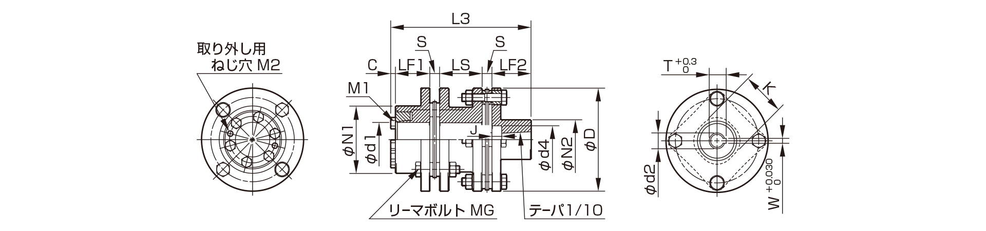
| models | d2 Nominal size | d1 | d2 | W +0.0300 |
T +0.30 |
d4 | J | D | N1 | N2 | L1 | L2 | L3 | LF1 | LF2 | LP | LS | S | C | d3 | K | MS | MW | MG | M1 | M2 |
|---|---|---|---|---|---|---|---|---|---|---|---|---|---|---|---|---|---|---|---|---|---|---|---|---|---|---|
| SFS-06 | 11C | 12, 14, 15 | 11 | 4 | 12.2 | 18 | 9 | 68 | 40 | 30 | 60.8 | 78.8 | 90.8 | 25 | 25 | 12 | 24 | 6 | 4.8 | 24 | 30 | 4-M6×25 | 8-M6×18 | 8-M6×25 | 4-M5 | 2-M5 |
| 16C | 15 | 16 | 5 | 17.3 | 28 | 10 | 40 | 75.8 | 93.8 | 105.8 | 40 | |||||||||||||||
| SFS-08 | 16C | 15, 16, 17, 18, 19, 20, 22 | 16 | 5 | 17.3 | 28 | 10 | 82 | 54 | 40 | 80.8 | 98.8 | 112.8 | 30 | 40 | 12 | 26 | 6 | 4.8 | 28 | 38 | 4-M6×29 | 8-M6×20 | 8-M6×29 | 4-M6 | 2-M6 |
| SFS-09 | 16C | 25・28 | 16 | 5 | 17.3 | 28 | 10 | 94 | 58 | 40 | 82.8 | 112.8 | 120.8 | 30 | 40 | 22 | 30 | 8 | 4.8 | 32 | 42 | 4-M8×36 | 8-M8×27 | 8-M8×36 | 6-M6 | 2-M6 |
| 30, 32, 35 | 68 | 90.8 | 120.8 | 128.8 | 38 |
- For the SFS(G) type, if you require a product with LS dimensions other than those listed, please specify the required LS dimensions. Additionally, if LS ≥ 1000, Contact Us.
- The nominal size for each bolt and tap is calculated as: quantity × thread size × nominal length.
- The dimensional tolerance for the mating shaft of the keyless locking hub is h7 (h6·g6).

Keyless Locking Hub SFS-□G
By incorporating a Keyless Locking mechanism into the hub, it is possible to achieve a installation with high accuracy.
Specifications (Keyless Locking)
| models | Permissible (operating) torque [N·m] | Permissible Tolerance | Max. rotation speed [min⁻¹] | Torsional stiffness [N·m/rad] | Axial stiffness [N/mm] | Moment of inertia [kg·m²] | Mass [kg] | ||
|---|---|---|---|---|---|---|---|---|---|
| Eccentricity [mm] | Angular misalignment [°] | In the axial direction [mm] | |||||||
| SFS-06G-□M-□M | 40 | 0.5 | 1 (one side) | ±1.6 | 5,000 | 14,000 | 22 | 0.55 × 10⁻³ | 1.10 |
| SFS-08G-□M-□M | 80 | 0.5 | 1 (one side) | ±2.0 | 5,000 | 41,000 | 30 | 1.56×10⁻³ | 2.00 |
| SFS-09G-□M-□M | 180 | 0.6 | 1 (one side) | ±2.4 | 5,000 | 85,000 | 61 | 3.10×10⁻³ | 2.80 |
| SFS-10G-□M-□M | 250 | 0.6 | 1 (one side) | ±2.8 | 5,000 | 125,000 | 80 | 4.70 × 10⁻³ | 3.50 |
| SFS-12G-□M-□M | 450 | 0.8 | 1 (per side) | ±3.2 | 5,000 | 215,000 | 98 | 12.10×10⁻³ | 6.50 |
| SFS-14G-□M-□M | 580 | 0.9 | 1 (one side) | ±3.6 | 5,000 | 390,000 | 156 | 25.31×10⁻³ | 10.10 |
- The permissible torque may be limited by the holding power of the shaft fastening section, so please check it using the standard bore size.
- The max. rotation speed does not take dynamic balance into account.
- The moment of inertia and mass are the values at the maximum bore diameter.
Dimensions (Keyless Locking)
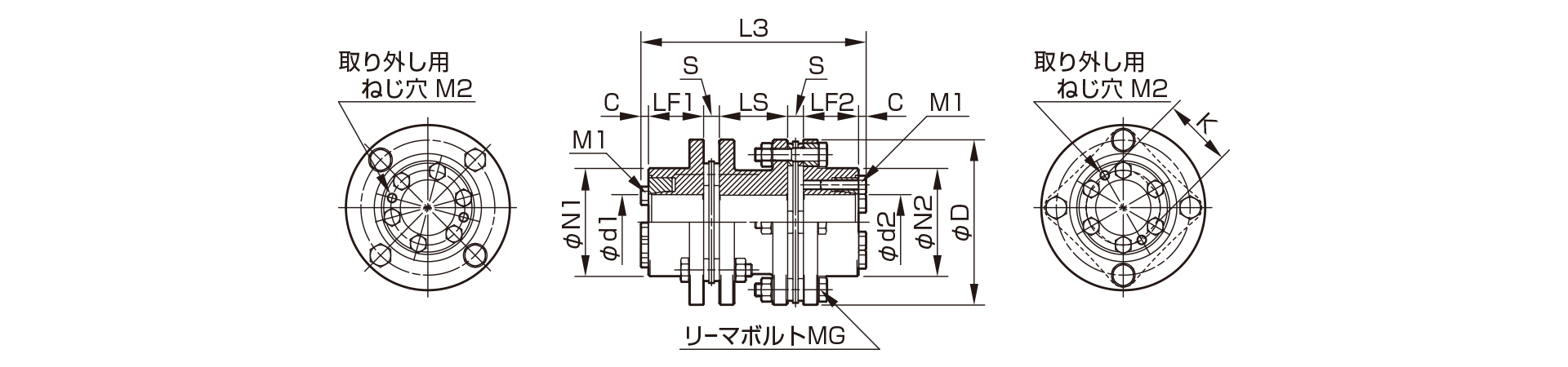
| models | d1 | d2 | D | N1 | N2 | L1 | L2 | L3 | LF1 | LF2 | LP | LS | S | C | d3 | K | MS | MW | MG | M1 | M2 |
|---|---|---|---|---|---|---|---|---|---|---|---|---|---|---|---|---|---|---|---|---|---|
| SFS-06 | 12, 14, 15 | 12, 14, 15 | 68 | 40 | 40 | 65.6 | 83.6 | 95.6 | 25 | 25 | 12 | 24 | 6 | 4.8 | 24 | 30 | 4-M6×25 | 8-M6×18 | 8-M6×25 | 4-M5 | 2-M5 |
| SFS-08 | 15, 16, 17, 18, 19, 20, 22 | 15, 16, 17, 18, 19, 20, 22 | 82 | 54 | 54 | 75.6 | 93.6 | 107.6 | 30 | 30 | 12 | 26 | 6 | 4.8 | 28 | 38 | 4-M6×29 | 8-M6×20 | 8-M6×29 | 4-M6 | 2-M6 |
| SFS-09 | 25・28 | 25, 28 | 94 | 58 | 58 | 77.6 | 107.6 | 115.6 | 30 | 30 | 22 | 30 | 8 | 4.8 | 32 | 42 | 4-M8×36 | 8-M8×27 | 8-M8×36 | 6-M6 | 2-M6 |
| 25, 28 | 30, 32, 35 | 58 | 68 | 85.6 | 115.6 | 123.6 | 30 | 38 | |||||||||||||
| 30, 32, 35 | 30, 32, 35 | 68 | 68 | 93.6 | 123.6 | 131.6 | 38 | 38 | |||||||||||||
| SFS-10 | 25, 28, 30, 32, 35 | 25, 28, 30, 32, 35 | 104 | 68 | 68 | 89.6 | 119.6 | 129.6 | 35 | 35 | 20 | 30 | 10 | 4.8 | 34 | 48 | 4-M8×36 | 8-M8×27 | 8-M8×36 | 6-M6 | 2-M6 |
| SFS-12 | 30, 32, 35 | 30, 32, 35 | 126 | 78 | 78 | 101.6 | 137.6 | 150.6 | 40 | 40 | 25 | 38 | 11 | 5.3 | 40 | 54 | 4-M10×45 | 8-M10×32 | 8-M10×45 | 4-M8 | 2-M8 |
| SFS-14 | 35 | 35 | 144 | 88 | 88 | 112.6 | 154.6 | 170.6 | 45 | 45 | 30 | 46 | 12 | 5.3 | 46 | 61 | 4-M12×54 | 8-M12×38 | 8-M12×54 | 6-M8 | 2-M8 |
- For the SFS(G) type, if you require a product with dimensions other than the LS dimension, please specify the required LS dimension. Additionally, Contact Us if LS is 1000 or greater.
- The nominal size of each bolt and tap is used to determine the quantity, which is calculated by subtracting the thread size from the nominal length and multiplying the result by the nominal length. The quantities for the M1 pressure bolts and M2 removal screw holes refer to the number on one side of the hub.
Standard Bore Size (Keyless Locking)
| models | Standard bore size d1 | Standard Bore Size d2 | |||||||||||||
|---|---|---|---|---|---|---|---|---|---|---|---|---|---|---|---|
| 12M | 14M | 15M | 16M | 17M | 18M | 19M | 20M | 22M | 25M | 28M | 30M | 32M | 35M | ||
| SFS-06 | 12M | ● | ● | ● | |||||||||||
| 14M | ● | ● | |||||||||||||
| 15M | ● | ||||||||||||||
| SFS-08 | 15M | ● | ● | ● | ● | ● | ● | ● | |||||||
| 16M | ● | ● | ● | ● | ● | ● | |||||||||
| 17M | ● | ● | ● | ● | ● | ||||||||||
| 18M | ● | ● | ● | ● | |||||||||||
| 19M | ● | ● | ● | ||||||||||||
| 20M | ● | ● | |||||||||||||
| 22M | ● | ||||||||||||||
| SFS-09 | 25M | ● | ● | ● | ● | ● | |||||||||
| 28M | ● | ● | ● | ● | |||||||||||
| 30M | ● | ● | ● | ||||||||||||
| 32M | ● | ● | |||||||||||||
| 35M | ● | ||||||||||||||
| SFS-10 | 25M | ● | ● | ● | ● | ● | |||||||||
| 28M | ● | ● | ● | ● | |||||||||||
| 30M | ● | ● | ● | ||||||||||||
| 32M | ● | ● | |||||||||||||
| 35M | ● | ||||||||||||||
| SFS-12 | 30M | 380 | 380 | 380 | |||||||||||
| 32M | 400 | 400 | |||||||||||||
| 35M | ● | ||||||||||||||
| SFS-14 | 35M | ● | |||||||||||||
- The bore sizes indicated by the ● symbol and the corresponding numbers in the table are standard. For bore sizes not listed in the table above, we may be able to accommodate them on a case-by-case basis, so Contact Us.
- For holes with numerical values, the permissible (operating) torque is limited by the Holding Power at the shaft fastening section due to the small bore size. The numerical values indicate the permissible torque [N·m].
- For bore sizes not listed in the table above, please note that the permissible (operating) torque may be limited if the bore size is small.
- The dimensional tolerance for the mating shaft is class h (7 h6·g6). However, for a bore size of φ35, the shaft tolerance is +0.010 and –0.025.
