SFS [W-C] Electroless Nickel Plating Type

This simplified anti-corrosion model features a W-type double-element body with an electroless nickel plating to enhance corrosion resistance. Since the shaft is typically secured using a key and set screw, please select the appropriate hole diameter and keyway specifications. As this product is supplied as a component, it allows for flexible assembly.
[Specifications]
| Model | Rated Torque [N·m] | Tolerance | Maximum rotational speed [min⁻¹] | Torsional spring constant [N·m/rad] | Axial spring constant [N/mm] | Moment of inertia [kg·m²] | Mass [kg] | Price [JPY] | ||
|---|---|---|---|---|---|---|---|---|---|---|
| Eccentricity [mm] | Angular offset [°] | Axial length [mm] | ||||||||
| SFS-05W-C | 15 | 0.2 | 1 (per side) | ±1.2 | 10,000 | 8,000 | 21 | 0.14×10⁻³ | 0.40 | 34,230 |
| SFS-06W-C | 30 | 0.3 | ±1.6 | 8,000 | 14,000 | 22 | 0.41×10⁻³ | 0.70 | 37,440 | |
| SFS-08W-C | 60 | ±2.0 | 6,800 | 41,000 | 30 | 1.10×10⁻³ | 1.30 | 43,330 | ||
| SFS-09W-C | 135 | 0.5 | ±2.4 | 6,000 | 85,000 | 61 | 2.20×10⁻³ | 2.10 | 47,810 | |
| SFS-10W-C | 190 | ±2.8 | 5200 | 125,000 | 80 | 3.60×10⁻³ | 2.80 | 52,280 | ||
| SFS-12W-C | 340 | 0.6 | ±3.2 | 4,400 | 215,000 | 98 | 9.20×10⁻³ | 4.90 | 71,800 | |
| SFS-14W-C | 600 | 0.7 | ±3.6 | 3,800 | 390,000 | 156 | 15.00×10⁻³ | 7.10 | 91,920 | |
- The maximum rotational speed does not take dynamic balance into account.
- The moment of inertia and mass are based on the maximum bore diameter.
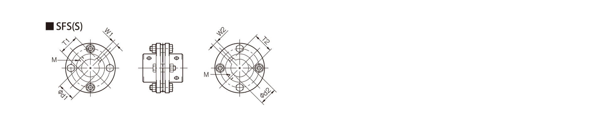
[Dimensions]

Unit [mm]
| Model | d1・d2 | D | N | L | LF | LP | S | F | d3 | K | M | |
|---|---|---|---|---|---|---|---|---|---|---|---|---|
| Min | Max | |||||||||||
| SFS-05W-C | 8 | 20 | 56 | 32 | 58 | 20 | 8 | 5 | 4 | 20 | 24 | 8-M5×15 |
| SFS-06W-C | 25 | 68 | 40 | 74 | 25 | 12 | 6 | 3 | 24 | 30 | 8-M6×18 | |
| SFS-08W-C | 11 | 35 | 82 | 54 | 84 | 30 | 2 | 28 | 38 | 8-M6×20 | ||
| SFS-09W-C | 38 | 94 | 58 | 98 | 22 | 8 | 12 | 32 | 42 | 8-M8×27 | ||
| SFS-10W-C | 16 | 42 | 104 | 68 | 110 | 35 | 20 | 10 | 7 | 34 | 48 | |
| SFS-12W-C | 19 | 50 | 126 | 78 | 127 | 40 | 25 | 11 | 10 | 40 | 54 | 8-M10×32 |
| SFS-14W-C | 22 | 60 | 144 | 88 | 144 | 45 | 30 | 12 | 15 | 46 | 61 | 8-M12×38 |
- The pilot hole is a drill hole. For machined holes, please refer to the standard hole machining specifications.
- The size of a Reema Bolt M is calculated as: quantity × thread size × nominal length.
[Standard Hole Diameter]
| Model | Standard Hole Diameter d1・d2 [mm] | |||||||||||||||||||||||||||
|---|---|---|---|---|---|---|---|---|---|---|---|---|---|---|---|---|---|---|---|---|---|---|---|---|---|---|---|---|
| 8 | 9 | 10 | 11 | 12 | 14 | 15 | 16 | 17 | 18 | 19 | 20 | 22 | 24 | 25 | 28 | 30 | 32 | 35 | 38 | 40 | 42 | 45 | 48 | 50 | 55 | 56 | 60 | |
| SFS-05W-C | ● | ● | ● | ● | ● | ● | ● | ● | ● | ● | ● | ● | ||||||||||||||||
| SFS-06W-C | ● | ● | ● | |||||||||||||||||||||||||
| SFS-08W-C | ● | ● | ● | ● | ||||||||||||||||||||||||
| SFS-09W-C | ● | |||||||||||||||||||||||||||
| SFS-10W-C | ● | ● | ||||||||||||||||||||||||||
| SFS-12W-C | ● | ● | ● | |||||||||||||||||||||||||
| SFS-14W-C | ● | ● | ● | |||||||||||||||||||||||||
- The hole diameters indicated by the ● symbol are standard hole diameters. For details, please refer to the standard hole machining specifications.

[Standard Hole Machining Specifications]
Unit [mm]
| Compliant with JIS B 1301 1959 (Type 2) | Compliant with JIS New Standard H9 JIS B 1301 1996 | New JIS Standard JS9 (Compliant with JIS B 1301:1996) | ||||||||||||
|---|---|---|---|---|---|---|---|---|---|---|---|---|---|---|
| Nominal hole diameter | Hole Diameter (d1, d2) | Keyway width (W1, W2) | Keyway depth (T1, T2) | Set screw hole (M) | Nominal hole diameter | Hole diameter (d1, d2) | Keyway width (W1, W2) | Keyway depth (T1, T2) | Set screw hole (M) | Nominal hole diameter | Hole diameter (d1, d2) | Keyway width (W1, W2) | Keyway depth (T1, T2) | Set screw hole (M) |
| Nominal hole diameter | Tolerance H7, H8 | Tolerance E9 | - | - | Nominal hole diameter | Tolerance H7, H8 | Tolerance H9 | - | - | Nominal hole diameter | Tolerance H7, H8 | Tolerance JS9 | - | - |
| 8 | 8+0.0220 | - | - | 2-M4 | 8H | 8+0.0220 | 3 + 0.0250 | 9.4+0.30 | 2-M4 | 8J | 8 + 0.0220 | 3±0.0125 | 9.4+0.30 | 2-M4 |
| 9 | 9 + 0.0220 | 9H | 9+0.0220 | 10.4+0.30 | 9J | 9 + 0.0220 | 10.4+0.30 | |||||||
| 10 | 10+0.0220 | 10H | 10 + 0.0220 | 11.4+0.30 | 10J | 10 + 0.0220 | 11.4+0.30 | |||||||
| 11 | 11+0.0180 | 11H | 11 + 0.0180 | 4 + 0.0300 | 12.8+0.30 | 11J | 11 + 0.0180 | 4±0.0150 | 12.8+0.30 | |||||
| 12 | 12 + 0.0180 | 4 + 0.050 + 0.020 | 13.5+0.30 | 12H | 12 + 0.0180 | 13.8+0.30 | 12J | 12 + 0.0180 | 13.8+0.30 | |||||
| 14 | 14+0.0180 | 5 + 0.050 + 0.020 | 16+0.30 | 14H | 14 + 0.0180 | 5 + 0.0300 | 16.3+0.30 | 14J | 14 + 0.0180 | 5 ± 0.0150 | 16.3+0.30 | |||
| 15 | 15 + 0.0180 | 17+0.30 | 15H | 15 + 0.0180 | 17.3+0.30 | 15J | 15+0.0180 | 17.3+0.30 | ||||||
| 16 | 16 + 0.0180 | 18+0.30 | 16H | 16 + 0.0180 | 18.3+0.30 | 16J | 16+0.0180 | 18.3+0.30 | ||||||
| 17 | 17 + 0.0180 | 19+0.30 | 17H | 17 + 0.0180 | 19.3+0.30 | 17J | 17+0.0180 | 19.3+0.30 | ||||||
| 18 | 18 + 0.0180 | 20+0.30 | 18H | 18 + 0.0180 | 6 + 0.0300 | 20.8+0.30 | 2-M5 | 18J | 18 + 0.0180 | 6±0.0150 | 20.8+0.30 | 2-M5 | ||
| 19 | 19 + 0.0210 | 21+0.30 | 19H | 19 + 0.0210 | 21.8+0.30 | 19J | 19 + 0.0210 | 21.8+0.30 | ||||||
| 20 | 20 + 0.0210 | 22+0.30 | 20H | 20 + 0.0210 | 22.8+0.30 | 20J | 20 + 0.0210 | 22.8+0.30 | ||||||
| 22 | 22 + 0.0210 | 7 + 0.06 1 + 0.025 | 25+0.30 | 2-M6 | 22H | 22 + 0.0210 | 24.8+0.30 | 22J | 22 + 0.0210 | 24.8+0.30 | ||||
| 24 | 24 + 0.0210 | 27+0.30 | 24H | 24 + 0.0210 | 8 + 0.0360 | 27.3+0.30 | 2-M6 | 24J | 24 + 0.0210 | 8±0.0180 | 27.3+0.30 | 2-M6 | ||
| 25 | 25 + 0.0210 | 28+0.30 | 25H | 25 + 0.0210 | 28.3+0.30 | 25J | 25+0.0210 | 28.3+0.30 | ||||||
| 28 | 28 + 0.0210 | 31+0.30 | 28H | 28 + 0.0210 | 31.3+0.30 | 28J | 28+0.0210 | 31.3+0.30 | ||||||
| 30 | 30 + 0.0210 | 33+0.30 | 30H | 30 + 0.0210 | 33.3+0.30 | 30J | 30 + 0.0210 | 33.3 + 0.30 | ||||||
| 32 | 32 + 0.0250 | 10 + 0.06 1 + 0.025 | 35.5+0.30 | 2-M8 | 32H | 32 + 0.0250 | 10 + 0.0360 | 35.3+0.30 | 2-M8 | 32J | 32 + 0.0250 | 10±0.0180 | 35.3+0.30 | 2-M8 |
| 35 | 35 + 0.0250 | 38.5+0.30 | 35H | 35 + 0.0250 | 38.3+0.30 | 35J | 35+0.0250 | 38.3+0.30 | ||||||
| 38 | 38 + 0.0250 | 41.5+0.30 | 38H | 38 + 0.0250 | 41.3+0.30 | 38J | 38+0.0250 | 41.3+0.30 | ||||||
| 40 | 40+0.0250 | 43.5+0.30 | 40H | 40+0.0250 | 12 + 0.0430 | 43.3+0.30 | 40J | 40 + 0.0250 | 12±0.0215 | 43.3+0.30 | ||||
| 42 | 42 + 0.0250 | 12 + 0.075 + 0.032 | 45.5+0.30 | 42H | 42 + 0.0250 | 45.3+0.30 | 42J | 42+0.0250 | 45.3+0.30 | |||||
| 45 | 45+0.0250 | 48.5+0.30 | 45H | 45+0.0250 | 14 + 0.0430 | 48.8+0.30 | 2-M10 | 45J | 45 + 0.0250 | 14±0.0215 | 48.8+0.30 | 2-M10 | ||
| 48 | 48 + 0.0250 | 51.5+0.30 | 48H | 48 + 0.0250 | 51.8+0.30 | 48J | 48 + 0.0250 | 51.8+0.30 | ||||||
| 50 | 50 + 0.0250 | 53.5+0.30 | 50H | 50 + 0.0250 | 53.8+0.30 | 50J | 50 + 0.0250 | 53.8+0.30 | ||||||
| 55 | 55+0.0300 | 15 + 0.075 + 0.032 | 60+0.30 | 2-M10 | 55H | 55+0.0300 | 16 + 0.0430 | 59.3+0.30 | 55J | 55 + 0.0300 | 16±0.0215 | 59.3+0.30 | ||
| 56 | 56 + 0.0300 | 61+0.30 | 56H | 56+0.0300 | 60.3+0.30 | 56J | 56+0.0300 | 60.3+0.30 | ||||||
| 60 | 60+0.0300 | 65+0.30 | 60H | 60 + 0.0300 | 18 + 0.0430 | 64.4+0.30 | 60J | 60 + 0.0300 | 18 ± 0.0215 | 64.4+0.30 | ||||
- The set screw and the keyway will not be on the same plane.
- The set screw is included with the product.
- The positional accuracy of keyway machining is checked visually.
- Please contact us if you require positional accuracy for the keyways relative to each hub.
- For standard dimensions of hole machining other than those listed here, please refer to the technical data at the end of this document.
【止めねじの位置】
| 型式 | 端面からの位置[mm] |
|---|---|
| SFS-05 | 7 |
| SFS-06 | 9 |
| SFS-08 | 10 |
| SFS-09 | 10 |
| SFS-10 | 12 |
| SFS-12 | 12 |
| SFS-14 | 15 |