What Are Gearboxes and Reducers? Their Types and Structures
2026/06/15
What Are Gearboxes and Reducers?
A reduction gear is a device that reduces rotational speed using gears or other mechanisms and outputs the reduced speed. It can output torque that is inversely proportional to the reduction ratio. A
speed changer is a device that alters the ratio of rotational speeds. While
a reduction gear operates at a constant speed, a speed changer allows the speed to be varied.
Why are gearboxes and reducers necessary?
Gearboxes and reducers are used to change the speed or reduce the speed of power generated by sources such as motors.
So why are gearboxes and reducers necessary? To understand this, we need to understand a little about motors.
A motor is also known as an electric motor, motor, or motor. While there are various types of motors used in industrial machinery and equipment, the most commonly used type is the three-phase induction motor, which is designed to operate on a three-phase AC power supply.
The number of revolutions per minute (RPM) of a motor is determined by the power supply frequency.
Taking a commonly used 4-pole motor as an example, since the power supply frequency in Japan is 50 Hz in the eastern region and 60 Hz in the western region, the motor rotates at a speed of 1500 rpm (1500 revolutions per minute) in the eastern region and 1800 rpm (1800 revolutions per minute) in the western region.
Now, let’s imagine a situation in a factory where products are moving along a conveyor belt. If the motor were operated at the speeds mentioned above, the conveyor would run at an incredibly high speed, making it impossible to handle.
Therefore, to obtain the required rotational speed from a motor rotating at a constant speed, speed changers and reducers are used to vary and reduce the rotational speed. In
other words, speed changers and reducers are almost always necessary when utilizing the power generated by a motor.
The motor rotational speed can be calculated using the following formula:
・Motor rotational speed N = 60 × frequency [Hz] / number of poles / 2 [min⁻¹]
(*As shown in the formula above, the supply frequency and the number of poles of the motor are factors that affect the rotational speed.)
Summary: The Role of Gearboxes and Reducers (Part 1)
・The rotational speed of motors and other components is varied or reduced using gearboxes or reducers.
The Principles of Shifting and Deceleration
As mentioned earlier, gearboxes and reducers are devices used to achieve the required rotational speed, but they also serve another important
function: generating rotational force (torque) proportional to the reduction ratio. For example, if the rotational speed is halved, the rotational force (torque) doubles.
This is because the mechanism of gear reduction utilizes the principle of the lever.
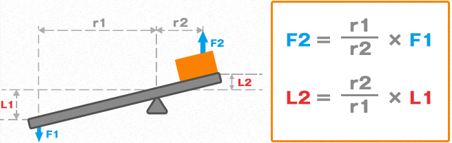
The figure above illustrates the principle of the lever, and the equation shown indicates that a large force F2 can be generated using a force F1. It also shows that the distance L2 traveled is shorter than the distance L1 traveled.
To illustrate this principle more clearly using a rotating body, the diagram below shows the following.
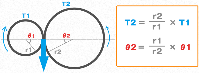
Therefore, reducing the rotational speed allows you to increase the rotational force.
Summary: The Role of Gearboxes and Reducers (Part 2)
・It is possible to obtain rotational force (torque) proportional to the reduction ratio.
The Difference Between a Transmission and a Reducer
While both are designed to reduce the motor’s rotational speed to achieve the required torque, there is a key difference: whereas a reduction gear operates at a constant speed, a variable-speed drive
allows the speed to be adjusted. One optimal method for power transmission involves first using a reduction gear to achieve a significant reduction in speed, and then using a variable-speed drive to fine-tune that speed.
Summary: The Roles and Differences Between Gearboxes and Reducers
・A reduction gear rotates at a constant speed, whereas a gearbox can vary the rotational speed

Types and Structures of Gear Reducers
While it is relatively easy to create a reduction mechanism by combining spur gears with different numbers of teeth, it is more common to use a pre-engineered reduction gearbox. Typical
reduction gearboxes include the following types. However, to achieve the required reduction ratio, it is common to combine the gears described below to create a reduction gearbox.
| Types | Features |
|---|---|
| Parallel-Shaft Gear Reducers | These reducers utilize spur gears and are available in configurations ranging from 1 to 4 stages, depending on the reduction ratio. Since power is transmitted through rolling contact, a transmission efficiency of approximately 98% per stage is achieved.They cover a wide range of reduction ratios, from approximately 1/5 to 1/2500. Since the number of gear stages varies depending on the reduction ratio, the dimensions of the reducer change according to the applicable motor output. |
| Helical Gear Reducer | Similar to parallel-shaft gear reducers, but using helical gears. Helical gears have teeth with a twisted profile, which improves the meshing ratio and results in smooth, quiet power transmission. However, because the teeth are angled, a thrust force is generated in proportion to the magnitude of the transmitted power. This weakness can be overcome by using a double helical gear system, which features helical gears arranged in opposite directions to cancel out the thrust force . |
| Bevel Gear Reducer | A reduction gearbox that combines bevel gears, typically with a 90° angle between the shafts.They reduce speed by combining a small pinion and a large gear, but are often used to shift the output by 90 degrees; for this reason, among bevel reducers, those with a reduction ratio of 1:1 are also called miter gears. Similar to helical gears, those with twisted tooth profiles to improve the meshing ratio are called spiral bevel gears (curved-tooth bevel gears). |
| Hypoid Gear Reducer | Unlike the spiral bevel gears described above, this type of gear features a pinion shaft that is offset by a certain amount from the centerline of the gear shaft. By incorporating slippage into the power transmission of the spiral bevel gears—similar to the worm gear reducer described later—it enables even smoother power transmission. Similar to worm gear reducers, they have a high tooth ratio, allowing for a high reduction ratio. However, because the meshing is complex, the meshing position must be precisely adjusted. |
| Worm Gear Reducer | A worm gear reducer consists of a worm gear (screw gear) and a worm wheel (helical gear). This combination alone provides a high reduction ratio of approximately 1/10 to 1/60.When the lead angle of the worm gear becomes small (resulting in a high reduction ratio), it is referred to as self-locking. This property makes it difficult to rotate the worm wheel (output side) from the opposite direction, and this characteristic can be utilized in applications such as preventing the descent of lifting devices. Furthermore, by minimizing thrust play in the input shaft, backlash can be reduced, making this a reduction gear with various advantages. However, compared to spur gears, power transmission relies on sliding along the tooth surfaces, which tends to generate heat, and the transmission efficiency is not particularly high, at around 50%. |
Types of Transmissions
When operating equipment that handles objects of varying shapes, sizes, and weights, operating the equipment at a single fixed speed can significantly reduce efficiency.
Therefore, it is more efficient for a single piece of equipment to be capable of operating at various speeds.
For example, if it is determined that two specific speeds are required, the equipment simply needs to be capable of producing those two speeds.
Possible methods include using a stepped transmission mechanism to switch speeds via a clutch, or stopping the machine temporarily to switch between the two output speeds.
However, it is far more convenient and efficient to be able to adjust the output speed continuously without stopping the prime mover.
This is what is known as a continuously variable transmission (CVT) in the classification of transmissions, as opposed to a stepped transmission.
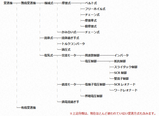
The continuously variable transmissions currently offered by Miki Pulley fall into the following categories.

We will cover the types and principles of belt-type continuously variable transmissions (CVTs) that use variable-pitch pulleys—a term that forms part of our company name—in this section. We will address the topic separately for electric motors such as DC motors, which are not three-phase induction motors, and for those that achieve speed variation by changing the frequency of the three-phase induction motor.
Types and Structures of Belt-Type Continuously Variable Transmissions
When considering the transmission of power from a drive unit (motor) to a driven unit (machine), common methods include couplings that transmit the motor’s output directly, gear systems such as reducers, and systems that rely on the engagement of chains and sprockets or belts and pulleys. In conventional belt-and-pulley power transmission
, the pitch diameter of the belt is fixed; the system is selected in advance to achieve the required rotational speed and torque, thereby maintaining a constant speed.
A belt-type continuously variable transmission (CVT) is a type of CVT that uses belts and pulleys; it varies the pitch diameter of the pulley on which the belt is mounted to adjust the constant rotational input. There are three main types of transmission methods.

| Types | Features |
|---|---|
| Intermediate Variable Pitch Type | An intermediate variable-pitch transmission is positioned between the driving and driven units. Speed is adjusted by moving the intermediate variable-pitch pulley toward either the driving or driven side. The intermediate variable-pitch pulley consists of two pulleys with V-grooves, and the pulley surface in the middle moves freely in the axial direction.By connecting the belt to one of the two V-grooves on the drive side and the other to the driven side, the positions of the drive and driven units remain fixed. Shifting the intermediate variable-pitch transmission changes the belt pitch diameter between the drive and driven units, thereby achieving speed variation.Since the design utilizes readily available standard V-belts, maintenance is straightforward. Furthermore, because the speed-changing function is achieved solely by the centrally positioned pulley, a cost-effective speed-changing mechanism can be realized. However, because it is installed between the driving and driven units and must be moved relative to both, the center distance increases accordingly, which may lead to an increase in the size of the equipment in some cases. > L-type, U-type, T-type |
| Single Variable Pitch Type | A fixed-pitch pulley is mounted on the driven side, while a single variable-pitch pulley is mounted on the driving side. Speed is varied by moving the driving unit to change the center distance. The single variable-pitch pulley is equipped with an internal spring that constantly exerts a force to close the pulley. Therefore, by increasing the center distance, the belt pushes the pulley’s spring outward, changing the pitch diameter to vary the speed.Models are available that use readily available standard V-belts and models that use high-capacity variable-pitch belts; both are suitable for applications requiring relatively small gear ratios. Additionally, a separate device is required to move the drive unit (motor). > P-type / PL-type (Standard V-belt) > PK-type / PF-type (Wide variable-pitch belt) > R-type / RK-type / RH-type (Motor moving platform) |
| Double Variable Pitch Type | Speed is adjusted by placing the single variable-pitch pulley described above on the driven side and a pulley capable of forced opening and closing on the drive side. A rotation handle is provided on the drive-side pulley, and the pulley face is opened and closed via a lead screw. A built-in spring on the driven-side pulley constantly applies a force to keep it closed. Therefore, by manually rotating the handle on the drive-side pulley to change the pitch diameter of both the drive-side and driven-side pulleys, speed changes can be achieved without altering the center distance between the shafts. Models are available that use readily available standard V-belts or high-capacity transmission belts, allowing for relatively large speed ratios. Furthermore, since there is no need to adjust the center distance, these units can be provided as integrated assemblies with motors and reducers. > PSS Type (Standard V-belt), AP Type + P Type > ANS Type , PDS Type, AHS Type (Wide Variable-Speed Belt), AK Type + PE Type > PDC Type, PDG Type, PDV Type, ANW Type, ANG Type, ACW Type, ANB Type, ANV Type, AHM Type (Belt-Type Continuously Variable Transmission Unit) |
List of Content
Our skilled engineers will select the right gearboxes and reducers for your equipment!
Are you experiencing any issues with your equipment?
At Miki Pulley, we can select and customize gearboxes and reducers from our wide range of options to perfectly suit your equipment! Please feel free to
contact us using the form below.