Glossary of Technical Terms
2026/05/07
This glossary of technical terms primarily contains explanations of terms excerpted from the Miki Pulley website and product catalogs. We hope it will be
useful not only for engineers but also for training new employees! While
the explanations are original, some sections are quoted from publicly available technical literature, such as JIS standards.
C
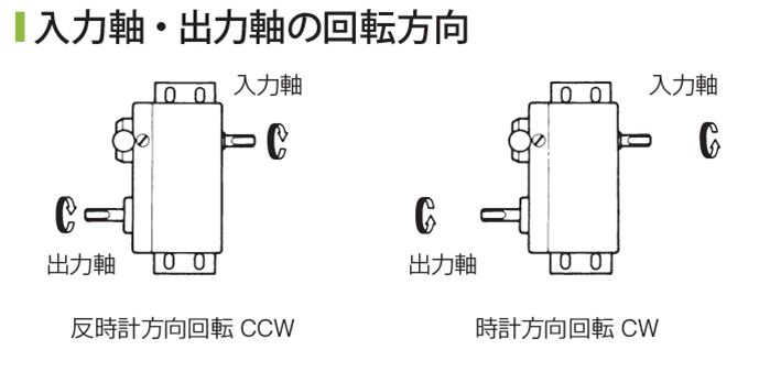
An abbreviated term for "counterclockwise." *"Clockwise" is abbreviated as "CW." For
Miki Pulley's "ZeroMax Continuously Variable Transmission," the model is selected based on the rotation direction of the output shaft.If the
model number includes the digit "1," it indicates counterclockwise (CCW) rotation; if it includes "2," it indicates clockwise (CW) rotation. The reason
for this separate selection lies in the mechanism of the ZeroMax CVT. Specifically, even if the input rotation is reversed, the output rotation direction cannot be changed. Therefore, please carefully consider the installation direction of the ZeroMax during the design phase. Note that there are also special models available that allow for forward and reverse rotation via lever operation.
⇒ Please also see the entry for "NC lathe."
NC (Numerical Control) stands for "numerical control," while CNC (Computer Numerical Control) stands for "computer numerical control."
Since CNC was developed in the 1970s and has been in use ever since, there is no longer a need to distinguish between NC and CNC; for all practical purposes, they can be considered the same thing.
A shorthand term for "clockwise.
" *"Counterclockwise" is abbreviated as "CCW."
E
⇒ Please also refer to the term "Export Determination Letter."
The EAR refers to the “Export Administration Regulations” under U.S. law. It applies to products and technologies that contain U.S.-origin items. If they do not contain such items, they are exempt. Therefore
, these regulations affect global trade. For example, when exporting from Japan to China, products containing U.S.-origin items are subject to the EAR. In other words
, even if the destination country is not the United States, you must still consider EAR compliance.
Consequently, when exporting products or technologies containing U.S.-origin goods from Japan to other countries, they are subject to the EAR’s “re-export controls.” *Note: The presence of U.S.-origin goods in Japan
means they were first exported from the U.S. to Japan. When those goods are exported from Japan to another country, it constitutes another export, which is why it is referred to as “re-export.”
Some Miki Pulley products are imported from the United States. Examples include the “Helical Coupling” and the “ZeroMax Continuously Variable Transmission” (certain models). Therefore
, in the “Export Classification Certificate” service provided on the Miki Pulley website, we have included an EAR classification section. For these products, the classification is not “Exempt” but rather “EAR99.”
⇒ Please also see the entry for "Pascal's Principle."
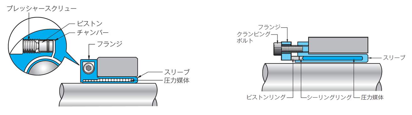
This refers to a friction-type fastener handled by Miki Pulley that secures a shaft and hub by applying pressure from a pressurized medium. Simply put
, it is a product in which an "ETP Bushing" inserted between the shaft and hub expands to secure them in place.
The friction-type fastener "ETP Bushing" combines both ease of installation and high precision in the connection of shafts and hubs.
⇒ Video: "Operating Principle of the ETP-E Friction-Type Fastener"
⇒ Video: "Operating Principle of the ETP-A Friction-Type Fastener"
H
A code number assigned to all trade items in accordance with the
HS Convention. The HS Convention is an international treaty concerning the Harmonized Commodity Description and Coding System, administered by the World Customs Organization (WCO).
In Japan, when filing import and export declarations with customs, you are required to enter a 9-digit number corresponding to the goods being declared; this number is called a "statistical number." The first six digits
of this number constitute the HS code. Since classification follows the same rules worldwide, the same number indicates the same commodity.
The reason the statistical number or HS code is required is to determine the applicable tariff rate. While tariffs vary by country, because the codes are standardized, you can immediately identify the tariff rate of the destination country even if you do not understand the local language.
I
⇒ Please also see the term "Motor."
⇒ Please also see the technical document "Specifications for Premium Efficiency Motors."
This refers to the efficiency classes of three-phase induction motors (three-phase motors). Motor efficiency standards are
classified into four categories:
・IE1: Standard
Efficiency ・IE2: High
Efficiency ・IE3: Premium
Efficiency ・IE4: Super Premium Efficiency *IE stands for "International Energy-efficiency Class."
Under the Top Runner Program of the Act on the Rational Use of Energy (Energy Conservation Act), three-phase induction motors became subject to the program starting in April 2015. The regulation requires manufacturers to produce three-phase induction motors with an output of 0.75 kW or more and an annual production volume of 1,500 units or more to meet the Premium Efficiency standard (equivalent to IE3).
As the efficiency class increases, electrical energy is converted into rotational energy more efficiently, resulting in reduced slip loss. Consequently, the motor’s rotational speed increases.
Since the motors comply with JIS standards, installation compatibility is maintained. However, because achieving Premium Efficiency requires larger dimensions compared to standard efficiency models, careful consideration is necessary when replacing existing units.
At Miki Pulley, three-phase induction motors (three-phase motors) are used in the following products: 《Electromagnetic Clutch and Brake Units》, 《Hollow-Shaft Speed Changers and Gear Reducers》, 《Solid-Shaft Speed Changers and Gear Reducers》, and 《Belt-Type Continuously Variable Transmission Units》.Motors with an output of 0.75 kW or more use IE3, while motors with an output of less than 0.75 kW use IE1.

J
This refers to the Japanese Industrial Standards, which are Japan’s national standards. JIS stands for Japanese Industrial Standards. Therefore, these standards are referred to as JIS or JIS standards. Previously known as the Japanese Industrial Standards
, they were renamed the Japanese Industrial Standards on July 1, 2019, following a legal amendment (the Reiwa era began on May 1, 2019). Note that the English name remains unchanged
.

L
LED stands for Light Emitting Diode. The semiconductor that contributes to the light emission of an LED
—that is, a semiconductor that emits light when an electric current is applied—is called an LED chip.
LED chips are manufactured by growing crystals on a sapphire substrate by depositing gases such as nitrogen and gallium. They consist of layered films formed during this growth process, including a "P-type layer," an "N-type layer," and a "light-emitting layer." Finally
, electrodes and protective layers are added on top of the light-emitting layer to complete the LED chip.
In an LED chip, the "P-type semiconductor" is in a state of electron deficiency (with many holes), while the "N-type semiconductor" has an excess of electrons; the "PN junction" formed by the P-type and N-type semiconductors constitutes the basic structure.
When a forward voltage is applied to the LED chip, electrons and holes move and collide. Upon collision, they recombine (a process known as recombination).
When high-energy electrons collide and recombine, their energy decreases, and this energy difference is converted into light. This is the mechanism by which LED chips emit light. These light-emitting LED
chips are arranged on printed circuit boards and other substrates to function as a light source for various components. This is called an LED module. Furthermore
, by combining LED modules with lighting control devices and other components, the light source unit for LED lighting fixtures is created.
First, the red LED was invented, followed by the yellow-green LED. Then
, Japanese scientists Akasaki, Amano, and Nakamura invented the blue LED, for which they were awarded the Nobel Prize in 2014. The invention of the blue LED completed
the three primary colors of light, making it possible to produce white LED lighting. In Miki
Pulley products, these LEDs are used in monitors that display the rotational speed of inverters and other parameters.
M
⇒ Please also see the entry for "NC lathe."
MC stands for “machining center.”
While NC machine tools such as NC lathes are automatically controlled during machining, the cutting tools—such as inserts—must be changed manually. A
machining center automates this process, making unmanned operation possible. Because the terms
“MC” and “NC” are similar both in
their names and in terms of machining automation, people often assume they have the same meaning, but their meanings are actually completely different.
N
⇒ Please also see the entry for "CNC lathe."
An NC lathe is a lathe that automates machining processes—which were previously performed manually—using numerical control.
Among NC lathes, those that are specifically automated and controlled by a computer are called CNC
lathes. The term "numerical control" is abbreviated as NC (Numerical Control). Therefore, machine tools that use numerical control—not limited to lathes—are also referred to as NC machine tools.
R
The RoHS Directive (Restriction of Hazardous Substances Directive) refers to the directive restricting the use of hazardous substances. The RoHS Directive (Restriction of the use of certain hazardous substances in electrical and electronic equipment) is an amendment to the original directive that took effect in Europe in February 2003, which was revised on July 1, 2006.
Its purpose is to restrict the use of hazardous substances in electrical and electronic equipment within the EU market (to levels below the permitted concentration), thereby preventing chemical substances harmful to the environment and human health from being released into the natural environment.
Under this directive, six substances—lead, mercury, cadmium, hexavalent chromium, polybrominated biphenyls (PBB), and polybrominated diphenyl ethers (PBDE)—were generally prohibited. Therefore
, although the RoHS Directive is European legislation, since it applies to imported products, similar regulations are required in Japan as well.
Subsequently, the "Revised RoHS Directive (RoHS 2)" came into effect on July 21, 2011, and on June 4, 2015, four phthalate esters were added as regulated substances, bringing the total to ten.
These substances are di(2-ethylhexyl) phthalate (DEHP), butyl benzyl phthalate (BBP), dibutyl phthalate (DBP), and diisobutyl phthalate (DIBP), and restrictions on their use will take effect on July 22, 2019. At the same time, the scope of the
regulation will be expanded to include medical devices and control equipment.
At Miki Pulley, we are committed to providing products that do not contain these restricted substances, and we display a mark on our website and in our catalogs to indicate which products comply with the RoHS Directive.
RoHS compliance certificates are available for download from our website; please feel free to use them.
⇒ Click here to download RoHS compliance certificates

S
"Quenching and tempering" refers to a process that combines quenching and tempering. Therefore, "S45C quenched and tempered" refers to S45C material that has undergone quenching and tempering. This
process makes the material harder.
In Miki Pulley products, S45C quenched and tempered equivalents are used for the outer sleeves, outer rings, inner sleeves, and inner rings of the "Mechanical Shaft Lock/Posilock" system, as well as for front and rear tapering.

W
The Web is a system that uses the Internet to transmit data.
The term "Web" is an abbreviation of "World Wide Web." It corresponds to the "www" in Miki Pulley's website URL
, "https://www.mikipulley.co.jp."
A
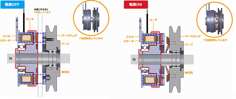
According to JIS standards, an “armature” is defined as a movable iron plate that forms a magnetic circuit. Since
an “armature” forms a magnetic circuit, it serves as a component in Miki Pulley’s “electromagnetic clutches and brakes.” Furthermore
, because it is described as a movable iron plate, it is clear that it is a moving part.
Let’s briefly explain the operating principle of an “electromagnetic clutch/brake” (
specifically, the excitation-type variety). When power is applied to the “electromagnetic clutch/brake” (i.e., the power is turned on), the coil built into a component called the stator becomes energized. The
stator then functions as a magnet. The stator is fixed to machinery or secured using a “rotation stopper” to prevent rotation.
Here, the stator and rotor are positioned side by side, but because there is a gap between them, they do not come into contact. Since the rotor is fixed
to the shaft, it rotates along with the shaft.
The magnetic force generated by the stator passes through the rotor and attracts the armature, which is a piece of iron. At this point
, the armature comes into close contact with the friction surface of the rotor. In other words, since it is attracted and moves in the axial direction, we can understand that it is a movable piece of iron. Consequently
, a magnetic circuit is formed between the stator, rotor, and armature.
Additionally, since components such as pulleys can be attached to the armature, the fact that the armature is in close contact with the rotor—which is fixed to the shaft—means that the pulley attached to the armature also rotates along with the shaft.
Note that a ring-shaped leaf spring is sandwiched between the armature and the pulley. The
leaf spring and the armature are secured using a component called a “rivet.” On the other hand
, the leaf spring and the pulley (or any other component specified by the customer) are machined by the customer according to their specifications and secured using the included bolts.
When the power is ON, the armature is drawn toward the stator and presses tightly against the rotor. At this time
, the leaf spring takes on a wave-like shape and spreads out to the left and right. When the power is OFF, the armature is pulled back by the restoring force of the ring-shaped leaf spring, thereby interrupting power transmission.
By understanding the movement and function of the armature in this way, you will also be able to understand the stator and rotor. Note
that in the case of a "non-excited brake," the operating principle differs from that of an "excited clutch/brake"; therefore, while it includes components such as the armature, stator, and rotor, it does not
have a leaf spring.
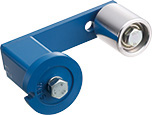
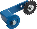
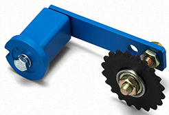
⇒ Please also see the entry for "sprocket."
When power is transmitted via belts or chains, the belts or chains stretch slightly over time. This stretching causes slack, which leads to vibration and noise and affects power transmission
. A device designed to eliminate this slack caused by stretching is called a tensioner, and the component attached to the tensioner that comes into contact with the belt or chain is called an idler.
Miki Pulley also offers products that function as tensioners. One such
product is the "Rosta Tensioner," available in the RSE model with a "pulley idler" or the NSE model with a "sprocket idler."
Additionally, the L model of the "Stand-alone Belt-Type Continuously Variable Transmission" features a "tension pulley" (the black component shown in the figure on the right) that performs a function similar to that of an idler.
In particular, the "Rosta Tensioner" is installed with a moderate preload applied to the belt or chain. This allows it not only to absorb slack and the resulting vibration and noise using Rosta rubber but also to automatically adjust and maintain the proper tension at all times during operation. As a result, there is no need to adjust the tension repeatedly during use.
Furthermore, since the contact between the belt and pulley or between the teeth and chain (wrap angle) increases compared to when slack is present, this also leads to improved transmission efficiency.
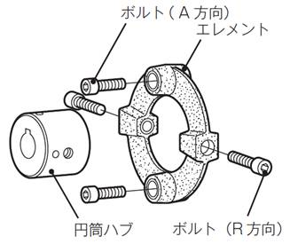
A term referring to the "parallel direction" relative to the center of the shaft on which the coupling is mounted. At Miki Pulley, in our "Centerflex Couplings," the bolts used to secure the rubber body or elements that are mounted parallel to the center of the shaft are referred to as "A-direction bolts" (where "A" stands for "axial").
Note that in terms of the coupling as a whole, when discussing tolerances, the term indicating the direction parallel to the center of the shaft is referred to as the “axial direction” (sometimes called the thrust direction) to distinguish it.
*The term corresponding to the axial direction (parallel direction) is the radial direction (perpendicular direction).
This is a surface treatment process in which aluminum is electrolytically treated as the anode (+ pole) to form an oxide film. It is also known as anodizing. Although “Alumite” is
actually a registered trademark of the RIKEN Research Institute, it is now used as a general term for oxide films produced by anodizing. Furthermore
, while aluminum is a metal, it is not iron and is therefore classified as a “non-ferrous metal.”
Aluminum naturally forms a thin oxide film because it readily reacts with oxygen. Therefore
, it can be used without undergoing an anodizing process; however, since it may corrode depending on the environment, anodizing is performed as needed.
At Miki Pulley, we use this process for the surface treatment of the clamp hub on our "Servoflex Coupling/SFC Model."
⇒ Please refer to the term "Service Factor."
i
An inverter is a device that allows the frequency and voltage of the AC power supplied to a motor to be freely adjusted, enabling stepless control of the motor’s rotational speed. Originally
, devices that converted DC to AC were called inverters, while those that converted AC to DC were called converters. As circuits were developed that allowed for the free adjustment of frequency and voltage, devices designed to control motors in this manner came to be known as inverters.
Before inverters existed, motor speeds were fixed, so speed variation was achieved using devices such as Miki Pulley’s “belt-type continuously variable transmission.” Furthermore
, since Japan has regions operating on both 50 Hz and 60 Hz, and global power conditions vary widely, significant ingenuity was required to achieve the desired speed.
With the advent of inverters, however, the motor’s rotational speed can be freely adjusted, making it possible to combine operations—such as performing one task quickly while performing another slowly. Today
, inverters have evolved to offer high motor efficiency and minimal rotational vibration even at low speeds. Furthermore, environmentally friendly features—such as energy savings and CO₂ reduction—have become standard specifications.
Miki Pulley’s “Inverter” incorporates a unique design philosophy cultivated through years of experience, featuring functions optimized for diverse small-capacity needs. The output frequency can be set up to 400 Hz
, and it comes standard with an automatic energy-saving function.
⇒ Please also see the term "spline."
An involute curve is the curve traced by the tip of a thread as it is unwound from a spool.In the spline coupling used in the
CF-H model of the "Centaflex," one of the shapes of the spline-machined grooves is the involute curve. A spline
machined in this way is called an involute spline. Features
of involute splines include high power transmission capacity and relatively easy machining.
An assembly method that uses protrusions and recesses to simplify alignment when joining parts by aligning the machined protrusion on one part with the recess on the mating part.
For Miki Pulley products, we recommend using alignment marks to ensure precise installation, such as when aligning the two shafts of a "coupling" or securing the brake mounting surface to the shaft of an "electromagnetic clutch/brake."
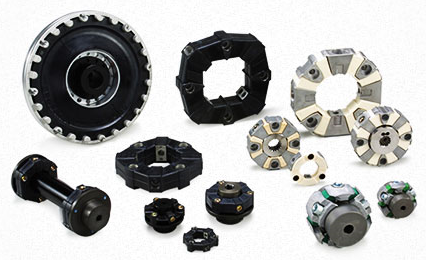
Eh
These are critical components for power transmission in couplings, and at Miki Pulley, we refer to them as "elements
." Elements are made of materials such as metal, resin, and rubber, and they are the components that most significantly affect the performance of a coupling (particularly its torsional spring constant and mounting tolerance).
In Japanese, they are sometimes referred to as "cushioning materials." Although the names differ—such as the "spider" in a "Spaflex coupling
" or the "metal coil spring" in a "Baumannflex coupling"—their function is equivalent to that of an element.
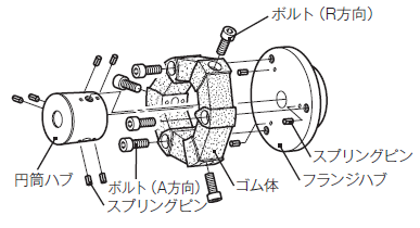
Generally speaking, the term refers to devices that convert energy into power; however, as the English word “engine” (which also refers to a locomotive) suggests, it specifically denotes an “internal combustion engine that generates power,” and is one type of prime mover—a machine or mechanism designed to produce power. The figure below shows an example of an engine’s flywheel (the component on the left side of the figure) connected to the drive shaft using a CF-A model “Centerflex Coupling” (the area shaded in blue in the figure).
In a "Centerflex Coupling," this is one type of hub used to secure the rubber body or elements. It is called a "
cylindrical hub" because of its cylindrical shape. Additionally, since the bolts used to secure the cylindrical hub to the rubber body or elements are installed perpendicular to the centerline of the shaft to which the coupling is mounted, they are referred to as "R-direction bolts" (where "R" stands for "radial").*The flange hub is another
type of hub used in conjunction with the cylindrical hub.

or
⇒ Please also see the term "EAR Determination."
When exporting "goods (products)" or providing "technology (such as software)" to foreign countries, this refers to the process of determining whether an export license is required to prevent weapons or goods and technology that can be diverted for military use from falling into the hands of parties that could threaten international security.
The "Non-Applicability Determination" document is sometimes referred to as a "Certificate of Non-Applicability."
When you export products or machinery, you are responsible for determining whether an export license application is required. However, since it is difficult for customers to assess Miki Pulley products on their own, Miki Pulley conducts these assessments in advance and publishes the results on our website under “Issuance of Non-Applicability Certificates.”
The determination assesses whether the product falls under "List Controls" or "Catch-All Controls" as defined by law.
"List-based controls" are determined by whether the product falls under items 1 through 15 of "Appendix 1 of the Export Trade Control Order" or "Appendix of the Foreign Exchange Order," while "catch-all controls" are determined by whether the product falls under item 16 of "Appendix 1 of the Export Trade Control Order" or "Appendix of the Foreign Exchange Order.
" Miki Pulley also conducts determinations regarding U.S. re-export controls (EAR determinations).
The term "shaft coupling" is known as a "coupling" in English. A shaft
coupling is a device that connects two shafts and serves to transmit power from one machine to another.
Most of the shaft couplings handled by Miki Pulley are "flexible couplings" (also known as "flexible shaft couplings"), which have the characteristic of being able to transmit rotation and power even when the centers of the shafts are misaligned. Conversely
, there are also couplings with very high rigidity that lack this flexibility; at Miki Pulley, we handle these under the name "Servo-Rigid Couplings."
⇒ Please also refer to the technical document "List of Formulas for Calculating Moment of Inertia (J)".
⇒ Please also refer to the technical document "Moment of Inertia (J) Quick Reference Table".
This refers to the degree to which an object is easy or difficult to rotate. Therefore
, a large moment of inertia means it is difficult to stop. For example
, in machinery that repeatedly switches between forward and reverse rotation, a large moment of inertia results in poor response to movements during startup and shutdown, which affects positioning accuracy.
The moment of inertia is expressed as the product of the mass M [kg] of a rotating body and the square of its radius R [m]. Furthermore
, multiplying the moment of inertia by angular acceleration yields rotational torque. Additionally, the natural frequency can be calculated from the moment of inertia and the torsional spring constant. As such
, the moment of inertia plays a very important role and is widely utilized in various applications, including mechanical precision and power calculations.
A gantry is a movable structure shaped like a gate. Therefore
, a gantry mechanism refers to a mechanism in which a gate-shaped component spans two parallel tracks and moves along them. Imagine a pedestrian
bridge moving along a sidewalk.
The Servoflex Coupling is well-suited for gantry mechanisms because high torsional rigidity is required to synchronize the movement of the two rails and ensure smooth operation. A common
example of a gantry mechanism is the "gantry crane," which is the type of crane found in ports that moves along rails to load and unload cargo from container ships.
ki
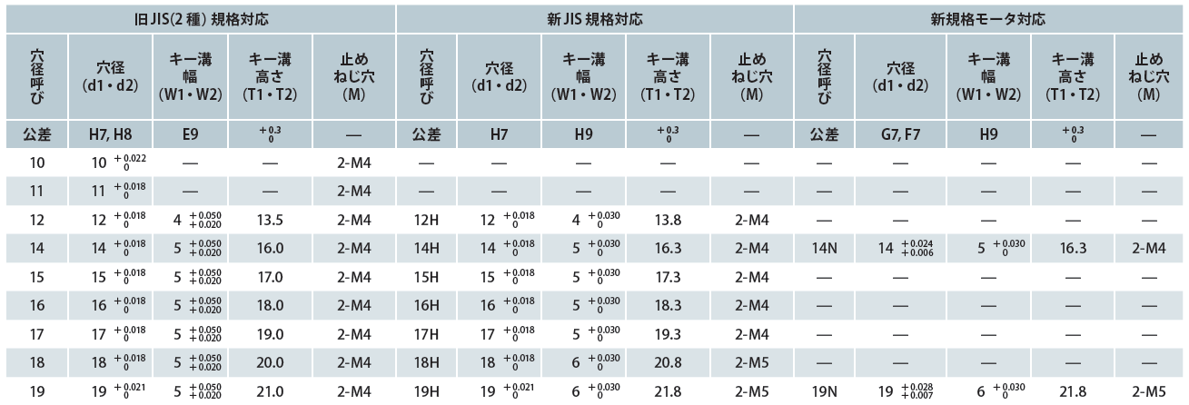
⇒ Please also refer to the technical document “Dimensions and Tolerances of Parallel Keys and Keyways” (excerpt from JIS B 1301 “Keys and Keyways”).
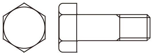
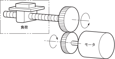
A key is a mechanical component used to connect a round shaft to a hub (such as a gear or pulley). Although the word "key" is the same in English as the keys used for homes and cars, the keys used in power transmission equipment are entirely different.
Simply inserting a hub with a round hole onto a shaft will cause it to slip as soon as power is transmitted. This makes it impossible to transmit power from the shaft to the hub. Therefore, using a key was devised as a method to secure the shaft and hub so they do not slip. In other words
, power transmission is achieved by the key. The strength of the key is, quite literally, the “key” to power transmission. Typically, keys are used in conjunction with a keyway. While there are various types of keys, the most commonly used is the "parallel key." Additionally, according to JIS standards, in addition to parallel keys, there are "tapered keys" and "half-moon keys."
Simply put, a parallel key is a rectangular metal bar. Furthermore, as shown in the figure below, keys are classified by the shape of their ends (both ends rounded, both ends square, or one end rounded). The key shown in the figure below is of the one-end-rounded type. On the other hand
, a keyway is a machined groove on both the shaft and the hub designed to accommodate the parallel key. This method is called a “sunk key.”
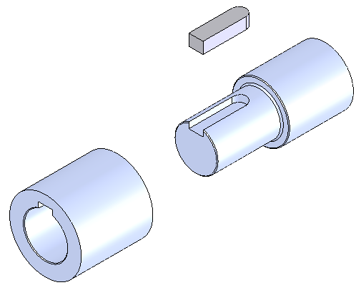
If a key is required to connect to your machinery, Miki Pulley offers a wide range of products—including couplings, electromagnetic clutches and brakes, belt-type continuously variable transmissions, and torque limiters—that come pre-machined with holes and keyways.
However, some shafts, such as those on servo motors, do not have keyways. There are also tapered shafts, where the tip of the shaft is slightly thinner and tapers.
For such cases, we offer "friction-type fasteners" such as ETP bushings as keyless mounting solutions, as well as "ServoFlex couplings" that use clamp hubs to secure tapered shafts via a clamping mechanism.
⇒ Please also see the term "natural frequency."
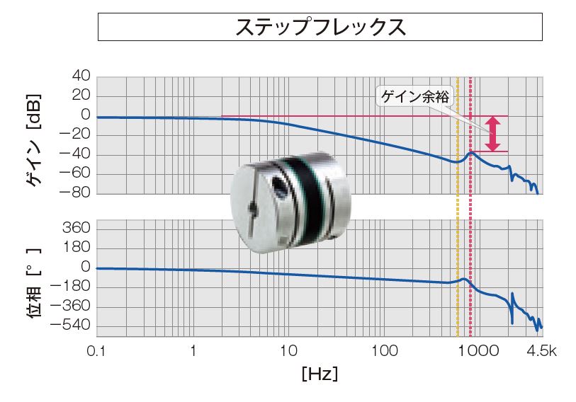
This refers to the phenomenon where the amplitude of vibration increases when an external vibration matching the natural frequency of an individual object is applied. It is used in both electrical and mechanical contexts. The loud rattling and shaking
of a washing machine during the spin cycle is also a resonance phenomenon. Some time ago, there was an incident where a bridge swayed violently due to wind; this was also caused by resonance. In electrical systems
, the resonance phenomenon caused by adjusting the gain of a servo motor is called "oscillation."
Since resonance causes significant vibration throughout the entire machine, it poses a serious
problem. To prevent resonance, it is necessary to calculate the natural frequency of the entire mechanical system formed by various machine combinations and adjust the frequency or rotational speed so that the externally applied vibration does not coincide with it.
Since the natural frequency is influenced by the torsional stiffness of the mechanical system, the torsional stiffness of the coupling, and damping characteristics, changing the coupling is one effective measure. For this reason
, the coupling specification tables in the Miki Pulley catalog list the torsional spring constant.
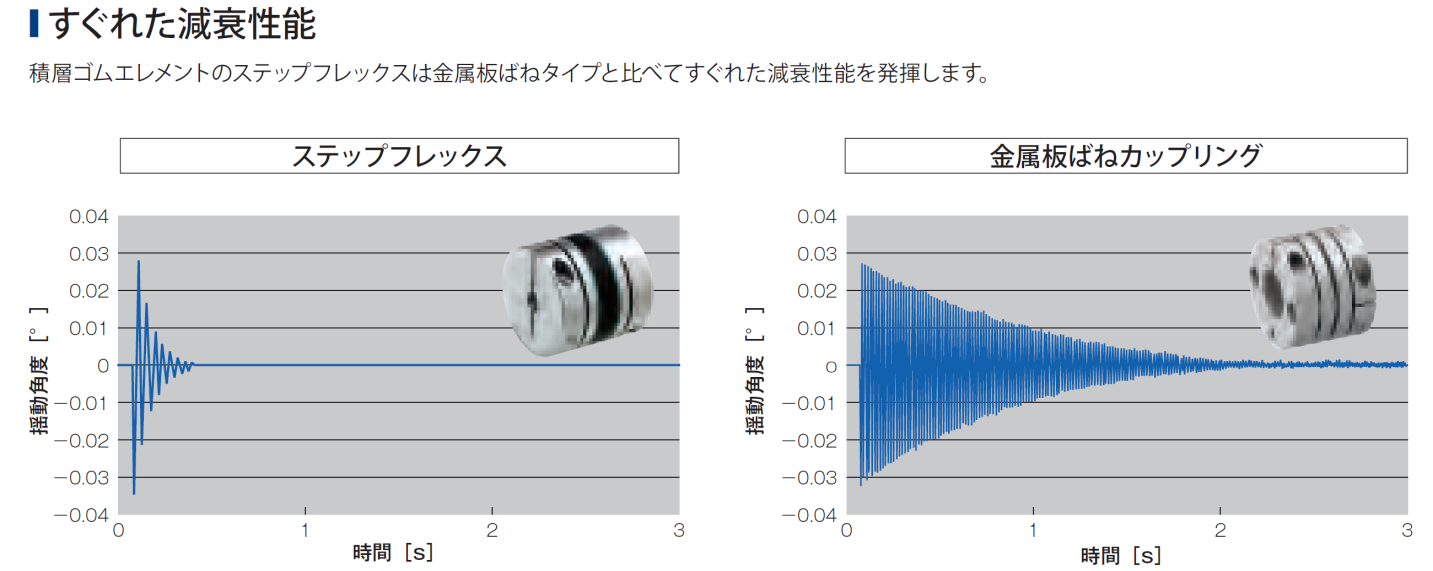
⇒ Video: "Vibration Countermeasures for Servo Motors at High Gain"
⇒ Video"Vibration Countermeasures for Stepper Motors at Resonance"
☆This video introduces solutions for suppressing vibrations caused by high gain in servo motors and pulsations due to resonance in stepper motors by replacing metal couplings such as the "Servoflex Coupling" and "Helical Coupling" with the "Servoflex Rubber," which features high damping performance using laminated rubber elements.
ku
⇒ Please also see the term "Clamping Hub." ⇒ Please
also see the term "Center Lock."
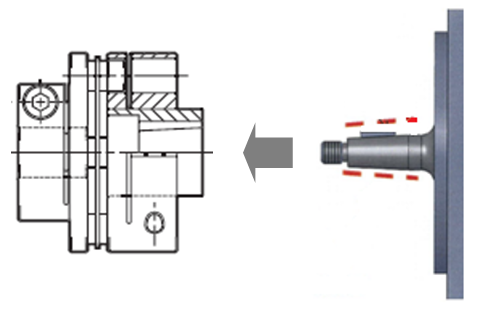
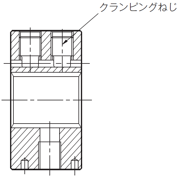
A specially shaped screw inserted into a threaded hole machined into the clamping hub to engage the center lock mechanism of the "Center Flex Coupling" and secure the clamping hub to the splined shaft. *Note
: There are also clamping bolts used to secure the hub and shaft; however, these are used with slotted clamping hubs, such as those found in the "Servo Flex/SFC Model."
⇒ Please also see the term "Clamping screw." ⇒ Please
also see the term "Center lock."
A hub designed to secure a splined shaft using the Centa-Lock mechanism. In a "Centa-Flex Coupling,
" the cylindrical hub that uses clamping screws is referred to as a clamping hub.
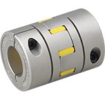
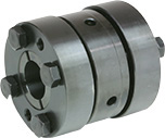
A general term for hubs with keyways in the following couplings: 《Servoflex Coupling》, 《
Servoflex Rubber》, and 《Starflex Coupling》. Additionally, the bolts used for clamp hubs are referred to as clamp bolts. *Note
: Since the 《Helical Coupling》 is a one-piece unit, it does not have a hub; however, the method of securing the shaft with clamp bolts is structurally identical.
*Note: The *Centerflex Coupling* features a clamping hub and clamping screws. Although the concept of securing the hub to the shaft is the same, the names are distinguished due to differences in structure. *Please note that
in Miki Pulley’s English-language catalog, “clamping hub” is also translated as “clamping hub.”*
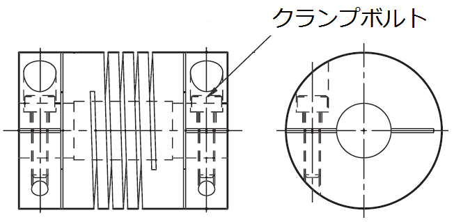
This refers to the bolts used in a clamp hub
. By tightening the clamp bolts to close the slot (sometimes called a slit) machined into the clamp hub, the hub and shaft are secured together. Tightening
the clamp bolts to the proper "tightening torque" ensures that the hub and shaft are securely fastened.
This is a surface treatment that prevents rust by forming an oxide film on the surface of steel.
Because it produces a glossy black finish, it is called a blackening treatment. It is also known as "ferric oxide coating" due to the formation of this oxide film.
Therefore, if the product is to be used or stored for an extended period, the surface must be protected with rust-preventive oil or similar agents. Please note that rust may form if the
product is stored for a long time after purchase.
Miki Pulley uses this treatment for the hubs of products such as the Servoflex Coupling (SFS Model) and the Servorigid Coupling. The advantage of blackening treatment is that
, since it is a chemical reaction, the coating will not peel off as can happen with surface treatments such as plating or painting. Furthermore
, because the coating is thin (depending on the processing time), it has virtually no effect on dimensional accuracy.
Procuring products with a low environmental impact. Alternatively, prioritizing procurement from manufacturers that demonstrate such consideration (i.e., those with established environmental management systems). This
approach encourages not only buyers but also suppliers to contribute to building a society with a lower environmental impact.
At Miki Pulley, we have published our "Environmental Protection
Policy" under "Company Information" on our website. This "Environmental Protection Policy" consists of our "Environmental Philosophy" and "Basic Environmental Policies," and one of the "Basic Environmental Policies" states: "We will actively promote the provision of green products to society."
ke
This refers to the ratio of the output to the input voltage, current, or power in a control system, and is measured in decibels. In Japanese, it is called "gain." Alternatively, since it indicates how many times larger the output is compared to the input, it could also be referred to as the "amplification factor."
Terms like "high gain" and "gain adjustment" are commonly heard in the context of high-precision, high-speed motors such as servo motors. In other words, increasing the gain increases the output, enabling higher precision and faster rotation. Note that modern servo motors automatically adjust to the optimal gain through auto-tuning.
However, if the gain is set too high, the motor will overshoot the target position and then attempt to return to it. This movement causes vibration, making manual gain adjustment necessary. Gain adjustment involves "position control," "speed control," and "torque control"; by adjusting to the optimal gain through a combination of these, the best high precision and high-speed rotation can be achieved.
Miki Pulley’s “ServoFlex Rubber” quickly dampens the vibrations generated even when set to high gain, enabling stable high-speed control.
⇒ Video: "Vibration Countermeasures for Servo Motors at High Gain"
☆ This video introduces a solution for suppressing vibrations generated by servo motors at high gain and pulsations caused by resonance in stepper motors by replacing metal couplings such as the "ServoFlex Coupling" or "Helical Coupling" with the high-damping "ServoFlex Rubber," which utilizes laminated rubber elements.
⇒ Please also see the term "Jump."
This refers to a new scheme developed by the Ministry of Economy, Trade and Industry (METI) for communicating information on chemical substances contained in products within the supply chain.
At Miki Pulley, we conduct chemical substance surveys to meet our customers’ needs, accurately reporting information obtained through supply chain communication and submitting files created using the chemSHERPA tool.
Damping refers to the phenomenon in which the amplitude of a vibration gradually decreases over time. The
shorter this time is, the higher the damping performance. One of the key advantages of Miki Pulley’s “Servoflex Rubber”—its “high damping performance”—stems from its ability to quickly absorb vibrations, which is made possible by the rubber material used in the coupling’s elastic element.
Flexible couplings that use metal for the elastic element are rigid in the torsional direction, making them excellent for power transmission; however, rubber is superior at absorbing vibrations. Therefore, we ask that you select the best coupling based on the precision, performance, and intended application of the machinery as required by the customer.
A term referring to the component that connects machinery such as motors, pumps, and engines. The
phrase "mount the coupling on the drive shaft" means the same thing as "mount it on the motor shaft."
This
⇒ Please also see the term "strain." ⇒ Please
also see the term "tensile strength."
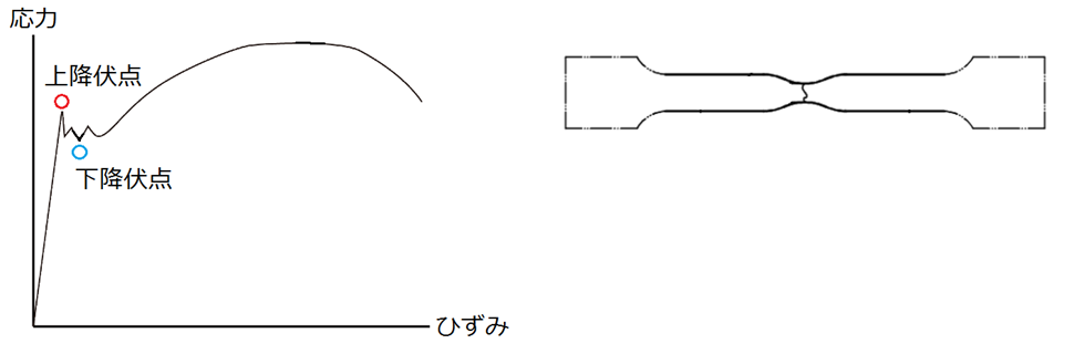
According to JIS G0202 "Steel Terminology (Testing)," this is defined as the maximum load during a tensile test on a metallic material, divided by the original cross-sectional area of the parallel section, prior to the start of yield in that section.
The "stress-strain diagram" shown in the figure represents the results of a tensile test expressed in terms of stress and strain (elongation divided by the original length and expressed as a percentage). In this diagram
, the initial straight line drops sharply, followed by a jagged section.This region, where stress remains relatively constant while strain increases, is called the "yield region." Within this region, the maximum stress is called the "upper yield point," and the minimum stress is called the "lower yield point." When there is no risk of confusion, it is acceptable to refer to the upper yield point simply as the "yield point."Note that for some
materials, the upper yield point is not shown on the stress-strain diagram; in such cases, the "point indicating the 0.2% proof stress" is defined as the yield point.
For Miki Pulley’s “Friction-Type Fasteners” and “ETP Bushings,” the catalog includes a “Design Verification Items / Hub Minimum Outer Diameter Table.” This table lists the minimum outer diameter dimensions of the hub required for the selected ETP bushing size, based on the material of the hub used by the customer
.
These hub outer diameter dimensions are derived from the yield point (the point at which 0.2% permanent deformation occurs) of the selected hub material; the "0.2" listed in the table refers to this value. Therefore, the point at which 0.2% permanent deformation occurs can be rephrased as "the point at which 0.2% permanent deformation is generated."
When securing the hub to the body of the 《ETP Bushing》, the hub-side sleeve of the body expands. The reason the "Hub Minimum Outer Diameter Table" is included in the catalog is that if the outer diameter of the hub used at this time is smaller than the value in the table, the hub will deform or break. In this way, the yield point, like tensile strength, is a critical value in material selection.
⇒ Video: "Operating Principle of Friction Fastener ETP-E"
⇒ Video: "Operating Principle of Friction Fastener ETP-A"
A process in which solid lubricants are formulated into a paint-like substance and applied as a coating to form a protective film.
Solid lubricants are also used to reduce friction and wear in areas where oil cannot be used, thereby improving lubrication.
At Miki Pulley, this process is used for the surface treatment of the clamping bolts on the "Servoflex Coupling/SFC Model" and the clamping bolts on the F-type/stainless steel version of the "Mechanical Shaft Lock – Posilock/PSL-K Model."
Generally, when tightening bolts, lubricant is applied to the bolt threads. However
, depending on the lubricant’s composition, the coefficient of friction may vary, leading to inconsistencies in tightening torque. Alternatively
, excessive axial force may be generated, posing a risk of damage to the clamping bolts or the coupling. Furthermore
, if lubricant enters the space between the coupling and the shaft, slippage occurs, adversely affecting the transmitted torque.
Therefore, to ensure consistent tightening torque and prevent lubricant from flowing, we apply a surface treatment using solid lubricants.
Furthermore, since the solid lubricant coating process allows for easy and large-scale application, it is also suitable for treating bolt surfaces.
⇒ Please also see the term "Resonance."
This refers to the natural resonance frequency of a structure. Every object
has its own unique natural frequency.
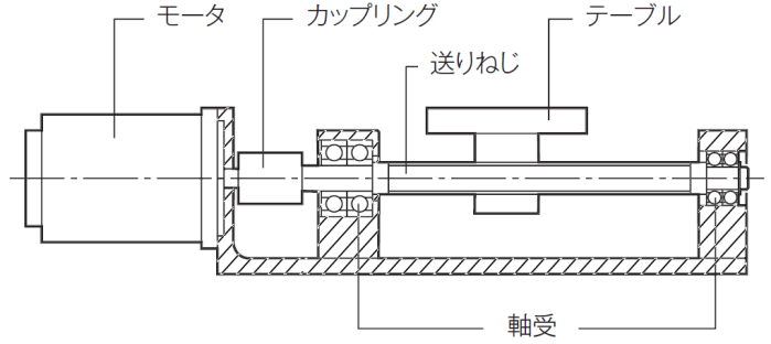
Particularly when selecting a coupling, if the natural frequency [in Hz] of the mechanical system (e.g., a lead screw system) matches the rotational speed of the coupling, a phenomenon called "resonance" occurs, generating vibrations strong enough to damage the coupling. Of course, these
vibrations are transmitted to the entire machine, adversely affecting precision. By determining the natural frequency in advance, resonance can be prevented by avoiding rotational speeds near that frequency.
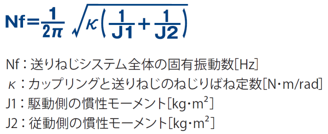
The natural frequency can be calculated using the "torsional spring constant" of the coupling and lead screw system, as well as the "moment of inertia" of the driving and driven sides.
Sa
⇒ Please also see the related term "Torque."
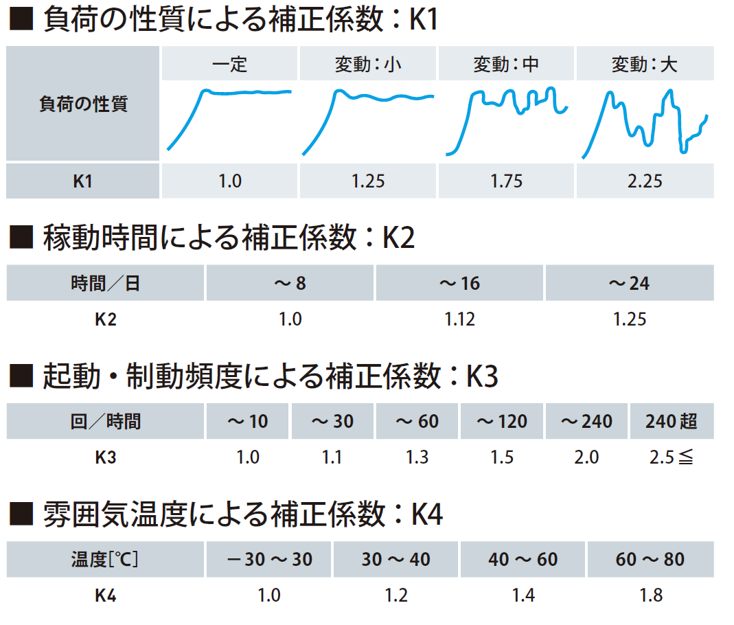
Simply put, it is the ratio of the reference value to the maximum value anticipated in the design. For example
, if the reference value is “the torque of 100 N·m at which the product fails and loses its function,” and the maximum value anticipated in the design is “the allowable torque of 50 N·m applied to the product,” then the service factor (safety factor) is 2. In other words
, if the product’s allowable torque is listed in the catalog, this means there is actually a safety margin of two times before the product fails.If the safety factor were 1, the product would fail as soon as the allowable torque is reached.
For example, with the "Starflex Coupling," the actual torque value Ta applied to the coupling is calculated, and then multiple service factors (referred to here as correction factors) determined by specific conditions are multiplied to derive the corrected torque Td. Next, the coupling is selected
so that this corrected torque Td is equal to or less than the Starflex's working torque Tn.
Additionally, Starflex couplings have a specified maximum torque Tm set at twice the working torque. Furthermore
, the torque at which the coupling will fail is determined by applying a safety factor that is a multiple of the maximum torque. Moreover, since unforeseen events such as impact may occur in practice—which can subject the coupling to significantly high torque—the safety factor is set with a generous margin to ensure the coupling does not fail under such conditions. In this way
, safety factors are incorporated at several stages to ensure reliable and worry-free operation.
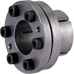
This is the product name for a metal plate spring coupling manufactured by Miki Pulley. As the name suggests, the
"Servoflex Coupling" was developed for high-speed, high-precision positioning and ultra-precise control applications, such as those involving servo motors. It offers high rigidity, high torque, low inertia, and high responsiveness, while also providing flexibility in the torsional, misalignment, and axial directions, and is completely backlash-free.
Furthermore, depending on differences in allowable torque and rigidity, the "SFC," "SFS," "SFF," "SFM," and "SFH" models are available.
The basic structure consists of leaf springs (elements) sandwiched between two hubs, and specifications vary depending on the number, shape, and
position of the leaf springs (single or double elements). While the tolerances are quite small due to the extremely high rigidity, inserting spacers between the hubs and leaf springs allows for larger tolerances.

A servo motor is a type of motor capable of controlling speed, position, and torque. To
control it, a sensor (rotary encoder) and a servo driver (amplifier) are required. Since many well-known motor manufacturers provide detailed explanations of servo motor structure and control on their websites, we will keep the explanation here brief.
Standard general-purpose motors simply rotate at a constant speed. By installing an inverter, the rotational speed can be adjusted by changing the frequency. Then came the DC servo motor
, which enables even more precise positioning and speed control.However, DC servo motors require "brushes," which are characteristic of DC motors, and these are subject
to wear. Consequently, brushless, maintenance-free AC servo motors were developed. These AC servo motors control torque by varying the amplitude of a sine wave (sine curve) current.
⇒ Please refer to the term "Rigid Coupling."
and
⇒ Please refer to the term "coupling."
⇒ Please also refer to the technical document "SI Units: List and Conversion Table."
This refers to the mass of an object itself, unaffected by gravity. In the SI unit system, it is expressed in kg (kilograms). An object is subject to the force of universal gravitation between itself and the Earth
. Additionally, because the Earth rotates, the object is also subject to centrifugal force. The
resultant force of this gravitational force and centrifugal force is "weight." It is known that an object weighs slightly less at the equator than at the North Pole. This is because the gravitational force differs due to the influence of centrifugal force.
Previously, the gravitational unit system (traditional units) was used, and weight was expressed as [kgf or kg-weight]. Looking at the unit itself, it is clear that
gravity is acting on the object. Therefore, it was decided to replace the gravitational unit system with the International System of Units (SI), which is not influenced by gravity. While
mass [kg] is now used, it is natural that the values for weight and mass differ by the amount of gravity. Let’s examine that difference.
Since objects are pulled toward the center of the Earth by gravity, as mentioned earlier, the relationship Weight = Mass × Gravitational Acceleration holds true. Furthermore, when
an object is dropped, it continues to accelerate at a constant rate; this is called gravitational acceleration and is expressed as 9.8 m/sec².
Furthermore, according to Newton’s Second Law, Force = Mass × Acceleration. Therefore, the force required to impart an acceleration of 1 m/sec² to an object with a mass of 1 kg is defined as 1 N (Newton).
Therefore, 1 kgf (weight) = 1 kg (mass) × 9.8 m/s² (gravitational acceleration) = 9.8 kg·m/s² = 9.8 N (Newtons).
Since 1 kgf = 9.8 N, this equation shows that a gravitational force of 9.8 N acts on an object with a mass of 1 kg.
⇒ Please read the entry for "torque wrench."
⇒ Please also see the term "ChemSherpa."
This refers to the Joint Article Management Promotion-consortium (JAMP). It was established in September 2000 to create mechanisms for the
appropriate management of information on contained chemical substances and for the smooth transmission of information throughout the supply chain.
*Article: An alternative term for parts, molded products, etc.
JAMP operates through the following specialized committees:
(1) "Technical Committee on Management Guidelines"… Development and dissemination of guidelines for the proper management of
chemical substances contained in articles; (2) "Dissemination Committee"… Promotion of
chemSHERPA; (3) "Tools Committee"… Maintenance and improvement of tools to support
the creation of chemSHERPA; (4) "Committee on Substances Subject to Management"… Monitoring trends in regulations and standards, and maintaining criteria and lists of substances subject to management.
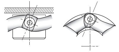
The part of a machine that is driven by a power source. Alternatively, the term used to describe the rotating component of a machine, such as a ball screw.
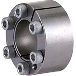
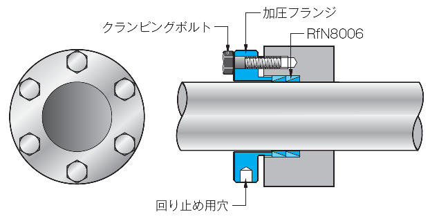
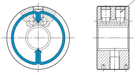
This component consists of two tapered rings (an outer ring and an inner ring) that are assembled to secure a shaft to a hub. The original
manufacturer of the Spahn ring is the German company RINGFEDER, and the product is marketed under the name "Locking Devices."
It features a simple and compact basic structure consisting solely of two tapered rings combined, securing the shaft and hub via a "wedge-lock" mechanism.
However, the Spahnring alone is not effective.A hole must be
machined into the customer’s hub to accommodate the Spahnring. Additionally, a “pressure flange” and “clamping bolt” are required to insert the Spahnring between the customer’s shaft and hub and secure it in place. It is also possible to use multiple Spahnrings depending on the required torque
.
Miki Pulley uses this as a component in its "Ring-Type Shaft
Lock/Friction Pack" system. Miki Pulley offers a convenient "Friction Pack" set consisting of the "RfN8006" + "Pressure Flange" + "Clamping Bolt."
Additionally, for "wedge fastening," Miki Pulley offers the "Mechanical Shaft Lock / Posilock" system. You can select the appropriate model based on your shaft diameter, as well as your mounting method and available space.
This refers to a standard established in 1983 (Showa 58) that revised the shaft diameters, key widths, and their tolerances for three-phase induction motors (three-phase motors).
At Miki Pulley, we have established the "Miki Pulley Standard Boring Specifications" for products such as couplings. Under these specifications, we sell products with bores pre-machined by Miki Pulley to match the shaft diameters and tolerances of "new-standard motors." Since customers do not need to machine the holes themselves
, these products are ready for immediate use.
As it has been approximately 35 years since 1983, the term "New Standard Motor Compatible" is now outdated, so "Motor Compatible" is also acceptable. Additionally
, while "New Standard Motors" is sometimes interpreted to refer to recent high-efficiency motors, this specification applies to all three-phase induction motors (three-phase motors) sold since 1984.
Furthermore, Miki Pulley’s standard hole-drilling specifications include “Compatible with Old JIS Standards” and “Compatible with New JIS Standards.” Since we used the terms “new” and “old” in this way when establishing the standard hole-drilling specifications and labeled them as “Compatible with New Standard Motors,” we continue to list them as such in our catalogs. Please note that we may eventually change this terminology
, and we appreciate your continued understanding.
s
These are industrial robots whose arms move horizontally; they are also known as horizontal articulated robots.
SCARA is an acronym for "Selective Compliance Assembly Robot Arm." SCARA
robots typically feature three types of rotational motion and one type of vertical motion. Because their rotating components are arranged horizontally, the robot’s axes are highly rigid in the vertical direction but flexible in the horizontal direction, making them well-suited for tasks such as inserting parts.
A motor that rotates in fixed-angle increments (like climbing a staircase one step at a time). The motor’s name derives from this “step” concept. It is also called a “pulse motor” because it
rotates by sequentially applying pulsed current (pulse signals).
The term "pulse" refers to a pulse or heartbeat, which repeatedly occurs for a short period and then ceases for the next short period.
A signal that repeats this on-off cycle at regular intervals is called a pulse signal. When represented graphically, it is referred to as a "square wave." Consequently
, because the on-off cycle repeats, the motor’s rotation appears jerky, to put it simply.
The mechanism behind this on-off action lies in the structure of the stepper motor. It consists of a rotor and a stator; the stator has iron cores arranged at equal intervals around its circumference. Coils are wound around these iron cores, so when current is applied in sequence, they become magnetized, causing the rotor to move. Reversing the order of this sequence results in reverse rotation.
To apply current to the stator coils in sequence, a pulse signal of a specific frequency must be generated and applied, which requires a dedicated circuit. Unlike a DC motor, which simply rotates when voltage is applied, this is not the case
here. However, the presence of this circuit means that various pulse signals can be applied, which in turn allows for a wide range of control options.
As mentioned earlier, the pulse signal is a square wave. By varying the width of this square wave—that is, by changing the frequency—the rotational speed changes. Furthermore
, each pulse of this signal determines the angle of rotation. In other words, changing the number of pulses changes the rotation angle, allowing the position to be adjusted. Since the rotational speed
can be controlled by frequency and the rotation angle by the number of pulses, this combination enables a wide range of control options.
Furthermore, changing the polarity of the current applied to the iron core reverses the direction of rotation. It is also possible to maintain the rotor’s position by continuously applying this current
.
While servo motors use "closed-loop control," stepper motors use "open-loop control." Since they do not require feedback like servo motors do, they can be described as "motors that are very easy to control." However
, the output power of stepper motors is not particularly high compared to that of servo motors. Consequently, they are commonly used in household appliances and office equipment. For example, they are often used in the paper feed mechanisms found in printers.
According to the international definition, it refers to an alloy composed primarily of iron (50% or more) and containing at least 10.5% chromium. It is generally referred to as "stainless steel."
Under JIS standards, the material designation for stainless steel is "SUS." This abbreviation stands for "Steel Special Use Stainless." In other words, "SUS" is not recognized internationally
. For reference, the Stainless Steel Association's website features a comparison chart with ISO standards and others.
When chromium is added to iron, it reacts with oxygen to form a thin protective film on the surface.
This protective film is called a passive film, and it prevents the progression of rust. Furthermore, although the film is thin, it is highly durable; even if the film is damaged, it automatically regenerates as long as oxygen is present.
Among stainless steels, the most widely used is "SUS304, containing 18% or more chromium."
Also known as 18% chromium stainless steel, it offers superior resistance to rust and corrosion—including corrosion resistance, acid resistance, and general durability—compared to other stainless steels.
In Miki Pulley products, SUS304 is used in the elements of the "Servoflex Coupling," the 3000 model of the "Helical Coupling" (labeled as equivalent to SUS304), and the sleeves of the F-type/stainless steel specification in the "Mechanical Shaft Lock – Posilock/PSL-K Model."

⇒ Please also see the entry for "wrench."
This is a tool designed to turn nuts or bolts of different sizes at one or both ends. "Spanner" is considered British English and seems to refer to any tool used to turn nuts or bolts in other countries. However
, given the shape of this spanner, it is limited to bolts with hexagonal heads. It cannot be used on bolts with round heads, such as those with hex sockets.
So, what is the name of the tool used to turn hex socket bolts (with a hexagonal socket on the head) that cannot be turned with a spanner? As you know, it is the "wrench," also known as a hex wrench or L-wrench. This term is considered American English.
In JIS standards, this hex wrench is officially designated as a “hexagonal bar spanner.”
⇒ Please also see the entry for "involute curve."
To transmit high rotational torque, numerous grooves resembling those of a gear are machined into the shaft and the hub that mates with it. The shape of these grooves is called a spline, and when these grooves form an involute curve, they are referred to as an involute spline.
In particular, spline couplings are frequently used for the hubs and shafts that utilize the
center lock feature of the "Centerflex Coupling."
⇒ Please also see the term "Centerflex."
A pin that connects adjacent components by driving it into a hole, utilizing the radial spring action created by rolling a flexible plate into a cylindrical shape.
In the CF-A and CF-H models of the "Centaflex Coupling," spring pins are used to connect the cylindrical hub or flange hub to the rubber body or insert. In other words
, the spring pins driven into the hub holes prevent the rubber body or insert from bending when tightened with bolts.
Without a spring pin, the rubber body would be fixed in a twisted position, which could lead to failure in a short period of time. However, since bending rarely occurs with smaller sizes, it is not necessary to use a spring pin.
⇒ Please also see the term "idler."
A sprocket is a gear used for power transmission via a chain. Generally
, the term "gear" refers to gears that mesh with one another. However, a sprocket is a gear that meshes with a chain to transmit power.
Since chains and belts stretch slightly over time, a device that eliminates this slack is called a tensioner. Miki
Pulley’s “Rosta Tensioner” features a “sprocket idler” that automatically compensates for slack during chain transmission.
The term "thrust" implies "pushing" or "pressing," and in Miki Pulley products, thrust force refers to the force applied in the axial direction (parallel to the shaft).
In Miki Pulley’s ETP bushings, the specifications list the “allowable thrust force.” This refers to the force applied in the same direction as the shaft on which the ETP bushing is mounted. In
contrast, a force applied perpendicular to the shaft is referred to as “radial.”
Note that in Miki Pulley’s coupling specifications, the English translation for “axial” in the permissible tolerance section is “Axial.”Although there is reportedly
little difference between "thrust" and "axial," if one were to distinguish them, "axial" is used in relation to the center of the shaft—that is, the shaft axis—while "thrust" is used in relation to the direction itself rather than the center of the shaft. Therefore
, it can be said that the term "axial" is used for couplings mounted on two shafts because the intention is to emphasize the relationship to the shaft axis.
For ETP bushings, the specifications list both the "allowable thrust force" and the "allowable radial load." It’s easy to understand why forces act in the radial direction—that is, perpendicular to the shaft. This is because when you mount a pulley or sprocket on an ETP bushing and transmit power via a belt or chain, forces perpendicular to the shaft are generated.
But why are the allowable values for the thrust direction also listed? Suppose, as shown in the figure, you
secure a rotating table using an ETP bushing. Since tables are almost always used horizontally, the table would shift downward if left unsecured. When you secure it, a downward force acts on the ETP bushing. In this case
, the downward force is parallel to the shaft, so it can be considered a thrust force. Therefore, the “allowable thrust force” must also be taken into account.
Se
⇒ Please also see the entry for "Spring Pin."
This coupling was developed by the German company Centa Antriebe and is produced in technical partnership with Miki Pulley. The product name is derived from the company name, Centa. The "Centa Flex
Coupling" falls under the category of rubber and resin couplings for power transmission. Rubber couplings utilize the elasticity of rubber, while resin couplings utilize the elasticity of resin to dampen and absorb shocks and vibrations.
A unique method used in Miki Pulley’s “CentaFlex Coupling” to securely fasten the splined shaft to the clamping hub (cylindrical hub). By tightening
the clamping screws, force is applied around the splined section to secure the connection.
A lathe is a machine tool in which the workpiece is secured in a chuck and rotated while a cutting tool (called a tool) is applied to it to remove material.
ta
This refers to a phenomenon in synchronous control where the phase difference between two machines becomes too large, preventing stable operation. Factors causing
the phase difference to increase include sudden large loads or the accumulation of control errors, which result in a loss of synchronization.
For example, to operate two separately installed conveyors in sync, the rotational speeds of their respective drive motors must be kept the same. To achieve this
, the output rotational speeds of each conveyor are detected and compared using sensors, and a signal to correct the speed difference is sent to the drive motors. The controller is the component responsible for correcting this speed difference.
One of the devices widely used to detect output rotational speed is the tachogenerator (also known as a tachogenerator). While
a tachogenerator generates a voltage proportional to speed, its analog nature means it cannot be considered highly accurate. Today, rotary encoders are used instead.
Miki Pulley offers the "Controller/OPC," which performs synchronous control via position control. In today’s era where high precision is essential, Miki Pulley’s Controller OPC continues to evolve. To achieve perfect synchronous control, we will continue to meet our customers’ needs by adding features such as synchronous signal output and out-of-sync signal output.
⇒ Please also see the technical document "International System of Units."
These are symbols placed before units to make the magnitude of a quantity easier to understand. For example
, 1 mm is read as “one millimeter.” This “milli” is a prefix. Similarly, since 1 km is “one kilometer,” “kilo” is the prefix.
Both share “meter” as the base unit, which is a unit of length. In the International System of Units (SI), it is one of the base units.
So, “milli” wasn’t actually a unit of measurement. And didn’t you perhaps think that “mm” in 1 mm was pronounced “milli”?
Setting that aside, since there are other units besides the kilometer—such as the kilogram and kilowatt—I hope you now understand that a prefix like “kilo” alone doesn’t convey its meaning.
Now, let’s take a look at the meter. In addition to millimeters and
kilometers, we also frequently use centimeters and micrometers. By using various prefixes like micro, milli, centi, and kilo, we can easily express that 1 m = 100 cm or 1,000 m = 1 km.
But even with the prefix “kilo,” which doesn’t convey its meaning on its own, don’t we all have a vague sense that it means “1,000 times” when we hear the word? Furthermore
, we often see terms like “giga” and “tera” used for data capacity these days, and if we hear that there is 3 terabytes of data, we can picture it and think, “Oh, that’s about that much.”
Isn’t this because the prefixes we see most often—kilo (10³), mega (10⁶), giga (10⁹), and tera (10¹²)—increase by a factor of 10³ each?
On a different note, weather patterns have become more extreme lately, leading to an increase in disasters caused by heavy rain. When you hear on the news that “50 millimeters of rain is expected,” those of you who have studied this far
are probably thinking, “Isn’t that a prefix?” or “What’s the unit for rainfall?” The correct answer is that rainfall is measured in “millimeters.” This is because it represents “height” or “depth.”
But why is rainfall measured in terms of depth? This makes sense once you understand how a “rain gauge”—the device used to measure rainfall—works. With a storage-type rain gauge, rainfall is measured by the amount of water collected in a measuring cylinder. There is also the tipping-bucket type. While the storage-type requires human operation, the tipping-bucket type is unmanned, so this type is now the most common.
In practice, how much water must accumulate to a depth of 1 mm to be considered 1 mm of rainfall? It is defined as 1 mm of rainfall when 1 mm of water accumulates over an area of 1 square meter (1 m × 1 m). In other words, that’s 1 liter. While rainfall is often reported as the amount falling over 1 hour
, it can vary depending on the situation—such as over 1 day or 10 minutes.
According to Japan Meteorological Agency data, the highest daily rainfall ever recorded in Tokyo was 371.9 mm in 1958. The highest hourly rainfall was 88.7 mm in 1939.
It is said that when rainfall reaches 30 millimeters in one hour, the risk of disaster increases dramatically, resulting in rain that feels like someone has turned over a bucket. This gives you an idea of just how intense that 88.7 millimeters was. You shouldn’t think of 30 millimeters as merely 3 centimeters. You might think that heavy
rain has become more frequent due to recent erratic weather, but that doesn’t seem to be the case. With this in mind, let’s keep in mind that there is always a risk of disasters occurring due to heavy rain.
T
A quantity that indicates the relationship between the rotational speed of a rotating object and the magnitude of the
resulting vibration. It can also be described as a measure, expressed in terms of mass and angle, of how far
the object’s center of gravity is offset from the center of rotation. In other words, good balance is also a measure of the magnitude of imbalance. Correcting this imbalance (balancing) reduces vibration.
While the JIS standard defines "balance" as "the product of the relative imbalance and the maximum practical angular velocity," I believe the introduction of terms like "relative imbalance" would only add to the confusion. Therefore, to make it simple and easy to understand, I have interpreted and described the meaning as stated in the opening paragraph.
Objects inherently contain areas of imbalance. Even a single component exhibits imbalance due to material heterogeneity or machining tolerances, and this imbalance accumulates as these components are assembled. This is referred to as “static imbalance.” That’s right—static imbalance exists even when
the object is not rotating. Simply mounting a relatively long shaft onto a machine causes the center to naturally sag (deflect).
Furthermore, when the shaft rotates, imbalance caused by centrifugal force occurs. This type of imbalance, which arises only when the shaft rotates, is called “dynamic imbalance.” If the total imbalance caused by centrifugal force is zero, the system is in a balanced state. However, this is practically impossible in reality. Thus
, “static imbalance” + “dynamic imbalance” = “total imbalance.”
One example of a Miki Pulley product that undergoes actual balancing before shipment to customers is the Servoflex Coupling (SFM Model). Generally
, balancing is performed by measuring the imbalance using a balancing machine and then correcting it.I’ve
heard that extremely high-precision balancing machines can detect unbalance as small as a fraction of a grain of rice, but if that’s the case, even the slightest scratch on the product would throw off the balance, so we have to be extremely careful when packing them into boxes. It’s one thing to perform balancing, but I don’t think it’s right if we can’t ship the product for an extended period afterward.
In this context, the rotational speed at which the customer will use the product and the required balance grade (a measure of how well-balanced it is) become critical factors.
JIS standards include a chart that specifies, by grade, the maximum allowable imbalance
corresponding to a given rotational speed. The numerical value representing the upper limit of balance quality directly corresponds to the balance grade, which is expressed as G2.5 or G6.3, for example
. At the same rotational speed, G2.5—which has a smaller upper limit value for balance quality—requires stricter balancing adjustments than G6.3.
For example, to meet the G6.3 requirement at 10,000 rpm, an imbalance of up to 5 μm is permitted, whereas the G2.5 requirement allows only up to 2 μm.
Similarly, at 20,000 rpm, the G6.3 requirement allows up to 3 μm, so as the operating rotational
speed increases, the balance correction requirements become stricter. As such, increasing precision raises costs, and in some cases, the limits may be exceeded, making balance correction impossible. This must be thoroughly considered during the design phase.
Balance grades (grades of balance quality) range from G0.4 to G4000, and there is a reference list summarizing the recommended balance grades for various types of rotating machinery. For
example, while G6.3 is listed for “machine tool and general machinery components,” “machine tool spindles” are recommended to meet G2.5.
Of course, when we speak of various rotating machinery, we are not limited to industrial equipment like machine tools. Our daily lives are filled with rotating objects—from electric fans and exhaust fans to CD players and computer hard drives. As long as there are rotating objects, the struggle with balance will continue. Moreover
, discrimination based on race, gender, and economic disparities exists in relationships between nations and among people, creating a state of imbalance. Unfortunately, however, there is still no balancing machine in the world capable of correcting this imbalance.
and
According to JIS standards, a decibel is defined as one-tenth of the unit of level (called a "bel"), which is the logarithm (to the base 10, or common logarithm) of the ratio of a given quantity to a standard reference value of the same type. Put very simply, it is a "unit that represents the ratio of two quantities."
The "deci" in decibel comes from "deciliter" (0.1 liter). Since it represents one-tenth of a liter, in the International System of Units (SI), it indicates a quantity that is one-tenth or 0.1 times the base unit.
There are various types of sound, encompassing a wide range of concepts such as sound intensity, acoustic energy density, and sound pressure. Although the unit was originally invented to express the attenuation of telephone signals, it is widely used in various fields beyond sound—such as vibration, electricity, and optics—because it is convenient for representing the ratio of two quantities.
Since sound is the vibration of air and can be described as a minute change in pressure, it can be expressed as “sound pressure” using the unit Pa (Pascal). However, the range of sound pressure is said to be 0.00002 to 20 Pa, a ratio of a staggering 1 million to 1. If we were to use a simple ratio, the scale would be too vast to display easily, so we use logarithms here.As you can see from the scale on a logarithmic graph, it allows us to compress and display values ranging from very small to very large.
At this point, I think you can somewhat understand the meaning of the phrase from the beginning: “the logarithm of the ratio of a certain quantity to a standard value of the same type (this is called a level).” From this
, we can see that the decibel as a unit of sound is derived by converting sound pressure. As mentioned earlier
, the decibel is a unit, and it is applied to physically measured values.
Noise is a value obtained by applying a correction to the measurement taken with a sound level meter’s A-weighting, and vibration (environmental vibration) is a value obtained by applying a correction to the amplitude measured by equipment. “Frequency” plays a major role in this correction
. Noise is not just about sound intensity, and vibration is not just about amplitude; both are expressed in decibels after accounting for human perceptual corrections based on differences in frequency.
Frequency refers to the number of times a wave repeats per second and is expressed in Hz (hertz). To illustrate this using sounds familiar to us, the human audible range is said to be 20–2000 Hz. Just as the human ear perceives lower frequencies as lower-pitched sounds, the perception of sound differs even when the sound pressure level is the same, depending on the frequency. Therefore
, sound intensity is expressed using sound pressure, with the unit being decibels.Pitch is expressed using frequency, with the unit being hertz. For example
, let’s assume the volume at the limit of human hearing is 0 decibels. Even though it’s called zero, it doesn’t mean complete silence or nothingness; it is merely a threshold value. This is because if we use
the number zero as a baseline, multiplying zero by anything results in zero, making it impossible to establish a ratio of “X times.”
For this reason, 0 dB is defined as 1x, which is equivalent to 100%. Furthermore, because ratios such as percentages are used, this system can be applied to comparisons in various fields beyond sound. Since logarithms are used, 20 dB represents a 10-fold increase, 40 dB a 100-fold increase, and 60 dB a 1,000-fold increase.
and
The total moment of inertia of a device in which the various components are interconnected, expressed in terms of the drive shaft (control shaft).
Suppose there is a device in which gear B, with a different speed ratio, meshes with gear A mounted on the motor shaft, and gear B is mounted on the load-side shaft. Suppose we are selecting a motor to rotate this device.Since the motor’s torque
is equal to the moment of inertia multiplied by the angular acceleration, the moment of inertia in this case must be the value relative to the motor shaft. This moment of inertia, expressed relative to the motor shaft, is called the “equivalent moment of inertia relative to the motor shaft.”
Let’s consider a simpler scenario. Suppose gear A is
simply meshed with gear B, which has a different speed ratio. If asked to calculate this moment of inertia, you might think that you could simply calculate the moments of inertia for gears A and B separately and then add them together to find the total moment of inertia.
However, gears A and B do not exist separately; they are meshed together and operate in unison.In other words, either gear A or gear B will be the driving gear, transmitting power. Since the value of the moment of inertia differs depending on which gear is the driving gear, the required output capacity for the driving gear also differs. Naturally, a smaller capacity for the driving gear is preferable. Therefore
, the moment of inertia for the entire interconnected mechanism cannot simply be calculated by adding the individual values together.
When Gear A is the driving gear, the equivalent moment of inertia is calculated using the following formula: Equivalent moment of inertia = Moment of
inertia of Gear A + Moment of inertia of Gear B × (Number of teeth on Gear B / Number of teeth on Gear A)² The key points here
are: “the moment of inertia of the driven side multiplied by the square of the speed ratio,” and “pay attention to the denominator of the speed ratio (if using tooth counts, the driving gear is in the denominator).”
Generally, a smaller gear (with fewer teeth and a smaller outer diameter) is used on the drive side of a machine to reduce speed. This is because, in most cases, the motor is on the drive side, and since high-speed rotation makes operation impossible, speed reduction is necessary. For example,
suppose Gear A has 22 teeth and Gear B has 44 teeth.When Gear B completes one revolution, Gear A must complete two revolutions. In this case, the speed ratio (also known as the reduction ratio or gear ratio) is 2. Since this value is greater than 1, it is immediately clear that Gear B, which is being driven, rotates more slowly.
In Miki Pulley’s “Belt-Type Continuously Variable Transmission Units,” the transmission ratio is listed in the specifications table as 1:4. This indicates that the output rotational speed ranges from 500 to 2000 min⁻¹. In other words, the unit can vary the speed over a range with a 4-fold difference.If you
combine the unit with an additional reduction gear to achieve a reduction ratio of 1/20, the output rotational speed will range from 25 to 100 min⁻¹. In this way, you can freely select the configuration to suit your specific application.
A patent is granted to an invention—defined as a specific description, in writing or through diagrams, of an idea that can be applied to industry—after it has been filed with the Patent Office and examined. Therefore, the patent system exists to promote the development of Japanese industry.
There was a story in a TV drama about the person who invented instant ramen. In cases like this, where someone conceives of something that did not previously exist in the world, it is recognized as a patent, allowing that person or their employer to hold exclusive rights. In other words, no one else can make it. However, since permanent exclusivity would hinder industrial development, patent rights are limited to 20 years from the date of application. After that period, the invention is returned to society, and anyone can make the same product.
*Incidentally, the person who invented instant ramen did not attempt to patent the invention to maintain a monopoly. Their wish was for anyone to be able to easily make delicious ramen using this technology, for the sake of Japan’s future. Thanks to that, we can now enjoy a wide variety of cup noodles from various companies.
Furthermore, the details of an invention are made public 1 year and 6 months after the filing date. If they were never made public, others might come up with similar inventions and file for patents. However, if a similar invention already exists, a later application will not be granted a patent. In other words, even if you put a lot of thought into it, you cannot monopolize it, which wastes both time and money—and this, too, hinders industrial development. Therefore, instead of granting exclusive rights, the system requires that the details of the invention be made public so that anyone can see them.
Furthermore, a patent is defined as a technical concept utilizing the laws of nature. Since ideas originate in the mind, they may include concepts that are not practical, and such concepts cannot be granted exclusive rights. Of course, industrial applicability is also a requirement, so concepts that can only be produced in a single instance (such as works of art) are not eligible for patents. Additionally, simply finding a new object constitutes a “discovery,” not an invention, and therefore is not eligible for a patent.
Regarding Miki Pulley products, the “Servoflex Coupling” holds patents for its product structure and manufacturing methods. To give one example, we have obtained patent rights in various countries for the slit machining shape of the hub shown in the figure.
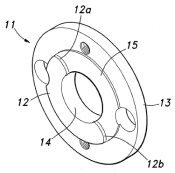
⇒ Please also refer to the technical document “Snap Ring (C-Ring/Retaining Ring/Stop Ring) Specifications and Dimensions Chart.”
A retaining ring is a ring-shaped spring that fits into a groove on
a shaft or in a bore to prevent axial movement. Retaining rings are a type of mechanical component known as a “spring.” You’ll realize this when you try to install one, because you have to expand or compress the ring. This can be quite difficult—I’ve lost count of how many times I’ve dropped one.
There are various types of retaining rings, such as "C-shaped retaining rings," "E-shaped retaining rings," and "grip retaining rings," with the "C-shaped retaining ring" being the most commonly used. These
C-shaped retaining rings are further categorized into "shaft-type" and "bore-type," as well as "eccentric" and "concentric." Therefore, when combined, you get "C-shaped eccentric retaining rings for shafts" and "C-shaped concentric retaining rings for bores," resulting in four distinct types of retaining rings.
Note that while “C-type retaining rings” are used in grooves, “E-type retaining rings” and “grip retaining rings” are used on shafts without grooves.
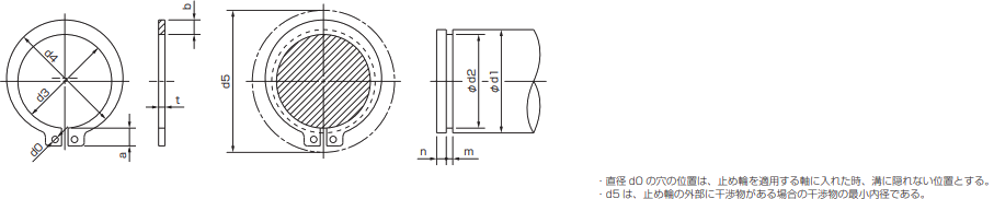
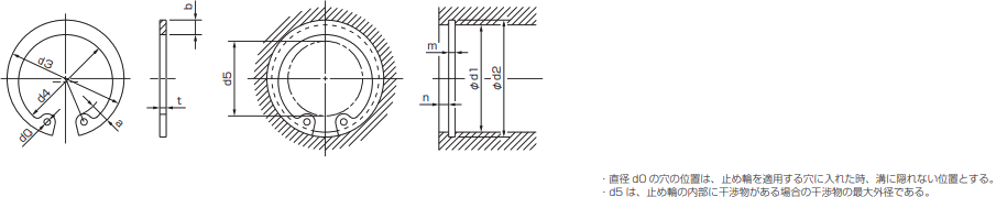
When installing or removing retaining rings, you will need a specialized tool (pliers) designed specifically for expanding and contracting them. Standard
pliers (such as needle-nose pliers) are generally ineffective for this task. This is because, while the tips of standard pliers typically contract when the handles are squeezed, retaining ring pliers are designed for a specific purpose: they must be able to expand.
According to JIS standards, the English translation for a retaining ring is “retaining ring.” However, various names have been used for them over the years. Since
they prevent axial movement—that is, they keep parts from moving—they are called “stop rings.” Because they make a “snap” sound when installed, they are also called “snap rings.” Additionally, C-shaped
retaining rings seem to be referred to as “circlips.”
There are terms similar to “snap ring,” such as “snap peas” and “snack peas
.” What is the difference between “snap peas” and “snack peas”?They are varieties imported from the United States in the 1970s, and they are actually the same thing. At the time
, snacks and other foods were made from this ingredient, and since they were convenient, easy-to-eat snacks, they came to be called “snack peas.” However, the Ministry of Agriculture, Forestry and Fisheries eventually standardized the name as “snap peas.” Incidentally, the origin of the
word “snap” comes from the fact that they are quite hard and “snap” when broken or make a “snap” sound.
⇒ Please also read the related term "service factor."
A value obtained by multiplying the force applied to rotate an object by the distance from the center of the object where that force acts. In other words, it is force × distance, with the unit being [N·m]. However
, in the context of couplings, torque is not indicated as the value required to rotate the coupling, but rather as the “value of power that the coupling can transmit.”
In Miki Pulley’s coupling specification tables, these values are listed as “allowable torque,” “rated torque,” or “maximum torque.” Allowable
torque is the value below which the coupling can be safely used; for relatively high-rigidity couplings such as the Servoflex, Servorigid, Baumannflex, and Schmidt, the “allowable torque” is indicated.
Furthermore, for couplings such as "Helical," "Spaflex," and "Belloflex,
" both "Rated Torque" and "Maximum Torque" are listed. While there is no issue if the coupling is used at or below the "Rated Torque," there are occasional instances where the torque applied to the coupling increases due to impacts or vibrations.
In such cases, the "Maximum Torque" should be considered; this is the torque that can be applied temporarily, and it is considered acceptable if it occurs only a few times a day.
Please note that these torque values may be limited to lower levels depending on conditions such as the coupling’s bore diameter and operating speed. Since specifications vary depending on the coupling you use
, please carefully review your operating conditions and select the appropriate coupling.
⇒ Please read the entry for "torque wrench."
⇒ The term "torque driver" refers to the same thing.
A tool used to tighten bolts and screws. To tighten bolts and
screws to the specified torque for their nominal size—for example, M8—it is not possible to rely solely on manual feel, so a torque wrench is necessary.
Tightening torque is specified to ensure that bolts and screws are secured with a certain amount of tension. The tension created between the threads
of the bolt and the screw hole prevents the bolt from loosening. Therefore
, if the tightening torque is too low, the bolt will loosen over time. If
a bolt loosens, it could fly out of a rotating product, potentially causing a serious accident.
Conversely, if the tightening torque is too high, the threads may be damaged. When this happens, the tension between the threads weakens, ultimately causing the bolt to loosen. As shown
, whether the tightening torque is too low or too high, the bolt will eventually loosen; therefore, it is essential to secure it using the specified tightening torque.One of
the factors contributing to coupling failure is the failure to properly manage the tightening torque of the coupling bolts or screws.
Torque wrenches are effective for tightening hex socket head cap screws and hex head bolts with relatively high torque. In addition
to torque wrenches,
there are torque drivers. Torque drivers can be used much like a Phillips screwdriver, making them effective tools for applications requiring low tightening torque, such
as hex socket set screws. Since each uses an attachment called a “head,” please select the appropriate one based on the shape of the bolt or screw.
For torque wrenches or torque drivers compatible with your product size, please refer to the "Servoflex" catalog, the "ETP Bush" catalog, or the "Posilock" catalog.
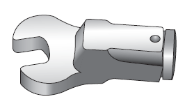
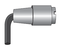
right
This value represents the torsional stiffness of a coupling and is expressed as the torque required to twist it in the rotational direction and the resulting angle of deformation. The unit
is [N·m/rad]. The
advantage of using a coupling with a high torsional spring constant is that it can transmit forces and movements from the input shaft directly to the output shaft. For example, in printing machinery,
this results in minimal misalignment during printing, leading to high-precision results.
Next, let’s compare torsional spring constants. Both couplings can be used
with servo motors and have the same outer diameter of Φ44. The Servoflex Coupling (SFC-040SA2) has a torsional spring constant of 20,000 N·m/rad, while the Servoflex Rubber (SFR-040SA1) has a torsional spring constant of 1,128 N·m/rad—a difference of approximately 20 times.
This demonstrates that the ServoFlex offers superior rigidity and responsiveness. However
, the StepFlex’s strengths lie in its “high damping and low reaction force.” This not only allows for rapid vibration damping but also enables the avoidance of resonance across a wide range of operating speeds. To ensure customers can select the right coupling for their specific applications
, Miki Pulley offers a wide variety of coupling options.
While Miki Pulley’s coupling specification tables typically display the “static torsional spring constant” (or simply “torsional spring constant”), the CF-A, CF-H, and CM models of the “Centerflex Coupling” series list the “dynamic torsional spring constant.”
The static torsional spring constant represents the relationship between force and deflection when force is applied slowly, while the dynamic torsional spring constant represents the same relationship when force is applied at a certain speed. Generally, the difference
between static and dynamic values is small for metals, but for rubber and resin couplings, the dynamic value tends to be larger than the static value. Therefore, we display the dynamic torsional spring constant as the value most suitable for actual use.
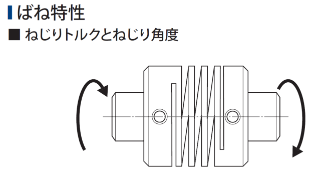
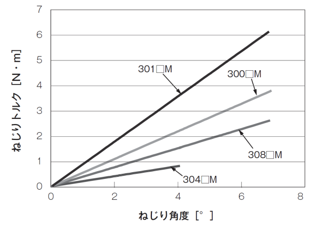
is
⇒ Please also see the term "ETP bushing."
This principle states that when a fluid (incompressible) is contained in a sealed vessel, the pressure exerted at any point is transmitted with the same intensity to all other points. This
means that the pressure of the fluid is equal at every point within the vessel. Furthermore, this principle is independent of the vessel’s shape.
A common example used to explain Pascal’s principle is a “U-tube” where the cross-sectional areas of the left and right tubes differ. For example, let’s assume the cross-sectional area of the left tube is 1 and that of the right tube is 5.(Units omitted)
If a force of 10 is applied to the left side, the right side is pushed up by 2. Furthermore, if a weight of 3 is placed on the left side, a weight of 15 must be placed on the right side to maintain equilibrium. The displacement is inversely proportional to the area, while the force is proportional to the area. Hydraulic jacks
utilize this principle, making it possible to lift a car using human strength. However, this requires a greater number of strokes (displacement) to achieve the same result.
Miki Pulley’s friction-type fastener, the “ETP Bush,” also utilizes Pascal’s principle. The sleeve
portion of the ETP Bush, where the shaft and hub come into contact, has a sealed structure. When pressure is applied to the pressure medium inside via a bolt, that force is transmitted directly to every point, ensuring that pressure is distributed evenly across the shaft and hub.
Therefore, if there are keyways or notches where the shaft and hub contact the ETP Bush sleeve, the sleeve will deform. Furthermore, if the contact length between the shaft and hub is insufficient, the sleeve will also deform. As a general rule, the shaft and hub should be designed so that they act against the sleeve over its entire length. Please note that if the ETP Bush deforms, it may become impossible to remove.
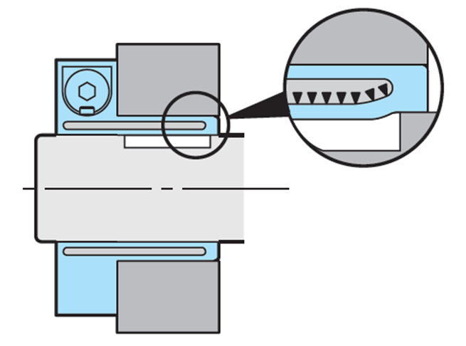
Backlash refers to mechanical play; specifically, it refers to the portion of the gear train where rotation is not transmitted when the gears are meshed. Therefore
, backlash is unsuitable for machinery that requires high positioning accuracy. Note that the term is sometimes written as “backlash.”
In the Miki Pulley catalog, one of the features listed for the "Servoflex Coupling" is "completely backlash-free." Since "
backlash-free" means there is no mechanical play, this coupling is suitable for high-speed, high-precision positioning and ultra-precise control applications, such as those involving servo motors.
The catalog features "feature icons" on the product lineup pages for each coupling to indicate their functions and performance; please refer to these when selecting a product.
An electronic component that reduces the reverse voltage generated when power to an electromagnetic coil is cut off.
At Miki Pulley, we refer to these as varistors or protective devices. Incidentally
, the staff who serve espresso at coffee shops are also called "baristas," but this term comes from the Italian word "barista."
The coils in electromagnetic clutches and electromagnetic brakes have a tendency to retain the current flowing through them. Therefore
, when the power is cut off—that is, when the current loop is forcibly opened—the energy stored in the coil is released as an excessive reverse voltage (back-EMF).
This back-EMF can cause adverse effects such as damaging semiconductor devices in the control circuit, degrading coil insulation, shortening the life of relays or causing welding, and generating noise from the current flowing through the wires.
Therefore, by connecting a varistor in parallel with the coil, the varistor absorbs the back EMF. However, the size of the varistor must be selected according to the voltage applied to the coil—that is, in accordance with the model and size of Miki Pulley’s “Electromagnetic Clutch/Electromagnetic Brake.”
The catalog includes a list of recommended “power supplies” for electromagnetic clutches and brakes (some models come with built-in varistors) and a list of varistors suitable for each model and size, so please use the appropriate varistor.
Using a hammer (also known as a "kanazuchi" or "tonkachi" in Japanese) to gently tap an object to adjust its position. For the Servoflex Coupling (SFF Model)
, the instructions specify that you should use hammering to adjust the outer circumference and end face of the flange as a means of aligning the shaft.
Hi
⇒ Please also see the term "tensile strength."
This refers to the value obtained by dividing the amount by which a material has stretched (the difference between its length after stretching and its original length) by its original length. This value is expressed as a percentage. *Note: While tensile force
is not the only type of force applied to materials, we are using tensile force for simplicity in this explanation.
When people hear the term "strain," many probably think of "strain gauges." A strain gauge is a sensor that is attached to a structure, for example, to measure how much the structure deforms when force is applied to it. So
why do we measure "strain"?As tensile force is applied to a material, it moves from the elastic region into the plastic region, where deformation occurs, and eventually breaks. In other words, it is important to measure how much force causes a structure to deform or fail. By measuring this with a strain gauge, the amount of strain can be displayed as a voltage, enabling numerical control. Therefore, we calculate strain to prevent structural deformation or failure.
As described, strain is calculated from the difference in length resulting from the force applied to the material; at this point, “stress” (force per unit area) is generated within the material. The
relationship between strain and stress is given by Hooke’s law: Stress = Strain × Modulus of Elasticity.
There are different types of strain. In addition to the tensile strain mentioned earlier, there are compressive strain, elastic strain, plastic strain, and shear strain; the type of strain depends on how the load is applied.
Furthermore, strain can be classified as longitudinal or transverse. When a material is pulled, it elongates in the direction of the applied load (the axial direction), but in the direction perpendicular to that, it shrinks and becomes thinner. This axial
strain is called longitudinal strain, and the strain in the perpendicular direction is called transverse strain; the ratio of these two strains is known as the "Poisson's ratio."
The kanji for "strain" is "歪み," but this same character has another reading: "yugami." Since they share the same characters
, there isn’t a huge difference in the fundamental meaning between "strain" and "yugami," but since they are distinct words, there are some differences.
In everyday usage, "hizumi" is used in phrases like "sound distortion" or "social distortion." Looking at the kanji for "hizumi," it is composed of "不" (not) and "正" (correct), meaning "
incorrect." Therefore, it seems to carry the connotation of being "incorrect," which likely explains why it is used in phrases like "social distortion.
" On the other hand, "yugami" is used in phrases like "facial distortion" or "character distortion."In
my personal view, “hizumi” feels more strongly associated with the “discrepancy” or “shift” from the original state rather than the deformation itself, whereas “yugami” conveys the image of the deformation itself. In any case
, please remember to use “hizumi” in the context of mechanics.
⇒ Please also see the term "Yield Point." ⇒ Please
also see the term "Strain."
According to the JIS standard (JIS Z2241 "Methods of Tensile Testing of Metallic Materials"), it is defined as the stress corresponding to the maximum test force.
*Here, stress is defined as the test force at any point during the test divided by the original cross-sectional area of the test specimen (the cross-sectional area before tensioning).
Additionally, JIS G0202 "Steel Terminology (Testing)" defines it as the maximum tensile load withstood by the test specimen during a tensile test divided by the original cross-sectional area of the parallel section of the test specimen.
*Note that in tensile testing, test conditions and specimen dimensions are specified, and the specimen has the shape shown in the figure (which depicts the specimen after fracture). Therefore
, while one might tend to think of tensile strength as the tensile load, it is actually stress, not load.
When steel materials are pulled, they stretch slightly, but if the pulling force is removed before reaching the yield point shown in the figure, they return to their original shape. This region is called the "elastic region." However
, once this point is exceeded, the material enters the "plastic region," where it deforms and does not return to its original shape. If pulled further, cracks form, and eventually, the material breaks.
The results of such tensile tests, expressed in terms of stress and strain (elongation divided by the original length and expressed as a percentage), are represented in the "stress-strain curve" shown in the figure. Note that there are materials for which the yield point shown in the figure does not appear on the curve. For example, materials like cast iron, which has low elongation, or stainless steel, which has high elongation, do not produce such a curve.
On this "stress-strain curve," the maximum stress at the position marked by the red circle represents the tensile strength. After that, the curve drops, and the material eventually breaks. When developing or designing products
, we must decide which materials to use to ensure sufficient strength. As one of the mechanical properties of a material, it is crucial to know the tensile strength value—the point beyond which applying further tensile load will eventually cause the material to break.
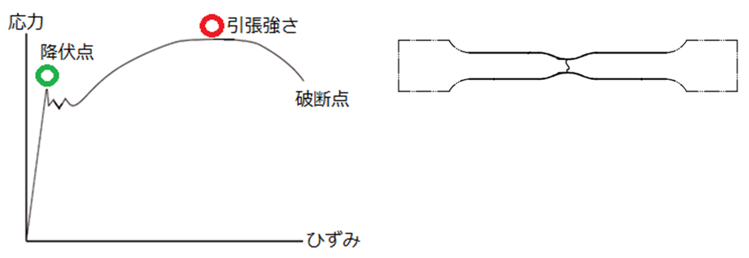
A general term for metals other than iron. Therefore
, since aluminum, nickel, zinc, magnesium, as well as gold, silver, and copper are all non-ferrous metals, all Olympic medals are made of non-ferrous metals.
The main difference between iron and non-ferrous metals is whether they are attracted to a magnet. Moreover, aside from iron, only a few metals—such as cobalt and nickel—are magnetized. So, what is the major difference
between aluminum and stainless steel, both of which are non-ferrous metals and are not attracted to magnets? It is their weight (specific gravity). As you likely
know, iron has a specific gravity of 7.8, and stainless steel also has a specific gravity of 7.8. However, aluminum has a specific gravity of 2.7.
For this reason, Miki Pulley’s various couplings—such as the “Servoflex Coupling/SFC Model,” “Servoflex Rubber,” “Starflex,” “Spaflex,” and “Belloflex”—use hubs made of lightweight aluminum alloy.
Making the coupling lighter reduces the moment of inertia, which improves the machine’s responsiveness and enables higher-precision control.
The JIS standard (JIS Z 8002) defines it as “an activity aimed at establishing specifications for common and repeated use, with the objective of achieving optimal order in a given situation regarding existing or potential problems.” Simply put
, when there is a problem of inconsistency in operations, the goal arises to eliminate that inconsistency and improve operational efficiency; by creating an operations manual and ensuring everyone follows it strictly, standardization of operations can be achieved.
For example, if there is inconsistency in how drawings are created, the person machining the part may end up finishing it with incorrect dimensions. This occurs
when the dimensions of the parts to be machined are not clearly specified, or when those dimensions cannot be determined without calculation. If the machining dimensions are
clearly specified relative to a reference surface, anyone can machine the part without error. In other words, it is beneficial to have a drafting manual that ensures the same drawing is produced regardless of who creates it.
Simply creating a basic drafting manual based on the principle of “always deriving dimension lines from the reference surface and clearly specifying machining dimensions” prevents errors and saves time. This benefits not only machinists but also drafters and inspectors, ultimately leading to the delivery of products with consistent quality to our customers. Please keep in mind that this approach allows you to achieve maximum results with minimal effort
.
Furthermore, once a manual is created, the work is essentially done (though periodic reviews are necessary). Therefore, rather than complaining that the time spent creating the manual is a waste, it is far more effective to simply create it. Another key
point is to simultaneously implement “visualization” so that the manual is readily accessible to anyone at any time. Without this, the manual will be nothing more than a wasted resource.
F
⇒ Please also see the entry for "Miki Pulley."
This refers to a pulley.
Historically, pulleys were devices installed above wells to hook ropes attached to buckets used for drawing water, making it easier to pull them up with minimal effort. Such
wells were called “wells with buckets,” but they are rarely seen today.
The shape of this pulley resembled that of a "belt-type continuously variable transmission (CVT) / standalone unit," and since our company achieved dramatic growth following the invention of the "belt-type continuously variable transmission (CVT)," this became the origin of the company name "Miki Pulley."
Don’t you think it’s easier to draw water from a well by threading the rope through a pulley installed above the well and pulling on it, rather than pulling the rope directly? Although the force required to lift the water is the same, this difference is likely due to the direction and posture used to pull the rope. It is many times easier to stand upright and pull the rope downward from the pulley than to bend over and pull the rope upward while looking into the well.
Naturally, humans tend to wonder if there isn’t an even easier way. Of course, methods like using a motor to automatically pull the rope or a pump to draw water are perfectly fine. However, there is a simple way to make the process easier without using that much equipment
. That is to add more pulleys. There is, of course, a way to do this. Until
now, we’ve fixed a pulley above the well. This is called a “fixed pulley.” The one we’re adding is a “moving pulley.” In other words, it’s a pulley that moves up and down.
Next, attach a bucket to the movable pulley. Pulling the rope hanging from the fixed pulley is the same as before, but the rope on the opposite side of the fixed pulley is routed under the movable pulley.Previously, the rope on the opposite side was tied to a bucket, but instead, we pass it through the movable pulley and secure the end of the rope to the ceiling. Then, just
as before, when you pull down on the rope hanging from the fixed pulley, the bucket attached to the movable pulley moves upward. Moreover, because the force exerted by the movable pulley is now added to the force exerted by the person pulling, the result is that the force required from the person is halved. However, the speed is also halved.Large cranes utilize this principle of halving the pulling force through the combination of a fixed pulley and a movable pulley. The next time you see one, try observing its movement closely while picturing a well or a pulley system.
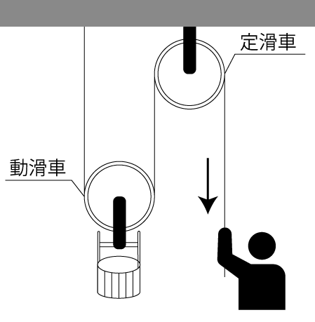
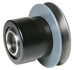
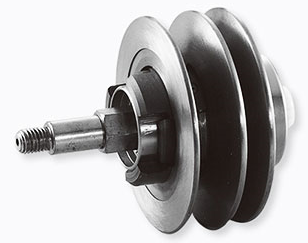
⇒ Please also see the term "Centerflex."
A flywheel is a disk used to stabilize rotation and is also known as a "flywheel." If the reciprocating motion of a piston caused by an explosion, as in an engine
, were directly transmitted to the rotational motion of the crankshaft, the rotation would not be smooth. Therefore, by installing a flywheel, rotation can be stabilized through inertia.
However, if the flywheel alone does not provide sufficient stability, a "Centerflex coupling" can be mounted directly on the flywheel and connected to the shaft. Since the "Centerflex" absorbs vibrations, this allows for extremely stable rotation. As such
, "Centerflex" is widely used in mechanisms driven by engines, such as construction machinery like excavators and the connection between engines and propulsion systems in ships.
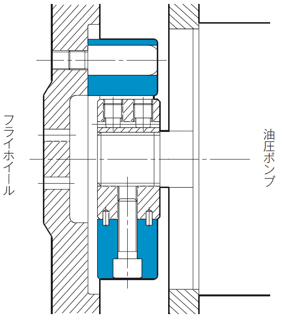
A "flange" refers to a "part that protrudes outward from a component in the shape of a rim," such as the wider section of
a flanged hub. Alternatively, the component itself with this shape may also be referred to as a flange.
One of the hubs used to secure the rubber body or elements in a "Centaflex coupling.
" Note that the bolts used to secure the flange hub and the rubber body or elements are installed parallel to the centerline of the shaft to which the coupling is mounted; therefore
, they are referred to as "A-direction bolts" (where "A" stands for "axial"). *The cylindrical hub is another type of hub used in conjunction with the flange hub.
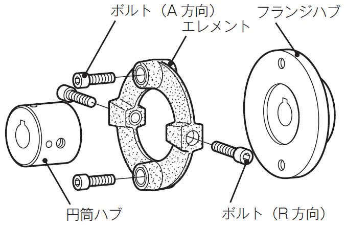
to
A mechanical component that supports a rotating shaft. While the JIS standard refers to them as "rolling bearings," they are generally referred to as "bearings." As the term "bearing" suggests, they are components that support or bear the weight of a shaft.
Bearings are classified into four types based on the direction of the load they can handle and the type of rolling elements, but the most commonly used type is likely the "radial ball bearing."A radial ball bearing is one in which the load direction is "radial" (perpendicular to the central axis), and the rolling elements are "balls." In addition to radial bearings, there are "thrust" bearings (parallel to the central axis), and in addition to balls, there are "rollers."
Simply put, the structure consists of an inner ring and an outer ring made of metal, with multiple balls arranged in a circular pattern between them so that they do not touch each other. Depending on the application, there are also shielded types filled with grease. Therefore
, power from the inner ring is not transmitted to the outer ring. As such, bearings are not designed to transmit power.
You might wonder, “If they can’t transmit power, why do we need them to support the shaft?” However
, even thin or short shafts generate a certain amount of runout when rotating due to factors such as machining accuracy and centrifugal force.
Furthermore, at high rotational speeds, this runout is transmitted as significant vibration. This leads to various adverse effects, such as rough machined surfaces and vibration throughout the entire machine. To address this
, plates with holes for the shaft are mounted on both sides of the rotating shaft. This supports the shaft, allowing it to rotate stably.However, friction soon develops between the shaft and the holes, causing the holes to enlarge or the shaft to seize in the holes. To prevent
such problems, bearings are fitted into the plates. These components are commercially available and are referred to as bearing housings, bearing units, or blocks. By passing the
shaft through the inner ring of the bearing and rotating it, the rotation becomes smooth, and friction is minimized. Thus, the role of a bearing is to ensure smooth rotation.
Bearings are classified by precision into grades such as 0, 6, 5, 4, and 2. Grade 2 has the highest precision and is used in applications such as the spindles of high-speed machine tools.
The figure below shows an example of an armature from Miki Pulley’s “Electromagnetically Actuated Clutch/Brake” product line mounted on a pulley. Two bearings are inserted side-by-side between the shaft and
the pulley. Even when the shaft is rotating, the armature remains separated from it, and since the shaft and pulley are connected via the bearings, the pulley does not rotate.
When power is applied, the rotor—which is fixed to the rotating shaft—and the armature are drawn together, causing the pulley attached to the armature to rotate as well. In this way, even when the shaft is constantly rotating, bearings play a crucial role in electrically operated clutch-brakes, which engage and disengage power transmission to the pulley.
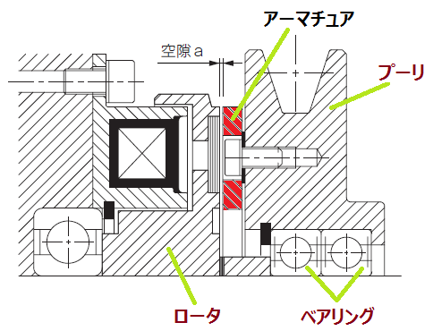
The figure below is taken from the Miki Pulley catalog for their "Couplings" and illustrates "How to Calculate the Natural Frequency of a Lead Screw System." It shows a lead screw (also known as a ball screw) connected to a motor via a coupling, with bearings at both ends. Supporting the lead screw with bearings in this way reduces the load on the motor.
However, we do not recommend adding bearings indiscriminately under the assumption that more bearings will provide greater stability. If a bearing is added outside the two bearings at both ends of the shaft, this creates a "three-point support" configuration, which can place excessive load on the central bearing.
Additionally, general-purpose motors already have two bearings built in to support the motor shaft. Therefore, be careful: adding just one bearing beyond the motor shaft creates a three-point support configuration, which places a load on the bearings inside the motor.

Ho
A "lead screw" is a type of screw in which balls perform a "rolling motion" between the peaks of the male thread and the valleys of the female thread. Because this rolling
motion reduces frictional resistance, it offers the advantage of high efficiency.
Ball screws consist of a screw shaft, nut, and balls; however
, they cannot transmit power on their own. By connecting them to a motor or other power source via a coupling, the rotational motion of the motor can be converted into linear motion. Consequently
, they are widely used in semiconductor manufacturing equipment, industrial robots, and for material handling and positioning in machine tools.
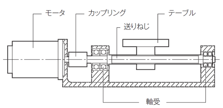
A machine that uses pressure to draw in or deliver liquids and gases. Wells are a common example of this principle in action. Similarly
, the mechanism in electric kettles—where pressing the top dispenses hot water—works on the same principle.
Well,
⇒ Please refer to the term "MC".
⇒ Please also see the term "Pulley." ⇒ Please
also see the term "Continuously Variable Transmission (CVT)."
Miki Pulley is a comprehensive manufacturer of power transmission and control equipment, developing, manufacturing, and selling products such as "couplings" (shaft connectors), "ETP bushings" (friction-type fasteners), and "electromagnetic clutches and brakes."
Miki Pulley was founded in October 1939 as "Miki Seisakusho" in Kawasaki City, Kanagawa Prefecture.
In 1954, the company obtained a patent for the “belt-type continuously variable transmission” and began manufacturing and selling it under the name “Miki Pulley Continuously Variable Transmission.” This further spurred technological innovation in Japan and played a significant role in the subsequent development of the industrial sector. Then
, in 1966, the company changed its name to “Miki Pulley Co., Ltd.” based on the product name. In Chinese, the company is known as “三木普利株式会社.”
Since then, we have expanded our product range to include couplings, electromagnetic clutches and brakes, as well as DC motors and inverters, continuing to support the power sources of all kinds of machinery. The Miki Pulley
logo currently in use was created to symbolize the three core concepts that embody the features and performance of Miki Pulley products: “changing speed,” “determining position,” and “transmitting rotation.”
⇒ Video: "Miki Pulley Company Profile"
⇒ Video: "This Is Miki Pulley"

Mm
⇒ Please also see the term "Pulley."
⇒ Please also see the term "Miki Pulley."
A machine capable of continuously variable speed control. Conversely, a bicycle’s 3-speed gear system, as the name implies, is a stepped transmission. Miki
Pulley handles a wide variety of continuously variable transmissions, including belt-type systems that use pulleys and belts for power transmission (such as the “Belt-Type Continuously Variable Transmission”), mechanical systems (such as the “ZeroMax Continuously Variable Transmission”), and electric systems (such as “DC Motors” and “Inverters”).
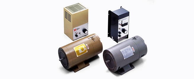

Me
Plating is a surface treatment process that involves coating the surface of metals or non-metals (such
as ceramics, plastics, and glass) with a thin layer of metal. In addition to preventing rust, plating is also used to improve
the appearance of the surface. Electroplating is a method that uses an electric current to deposit metal ions onto the surface of an object. When electrodes are placed in a solution containing metal ions, the current causes the metal ions to flow toward the negative (cathode) electrode, resulting in a plating layer on the surface.
"Electroplating (Electrolytic Plating)"
Electroplating is a method that uses an electric current to deposit metal ions onto the surface of an object. When electrodes are placed in a solution containing dissolved metal ions, the current causes the metal ions to flow toward the negative terminal (cathode), resulting in a plating layer on the surface.
Additionally, there is "chemical plating (electroless plating)," which does not use electricity. While the
terms "electrical" and "chemical" may be confusing, in electroplating, the metal must be soluble in the electrolyte solution for plating to occur. Chemical plating, on the other hand, uses chemicals. Compared to electroplating, it has limitations such as a maximum film thickness and a longer processing time. The advantages of electroless nickel plating include uniform plating thickness and the ability to apply a uniform coating even to parts with complex shapes.
"Electroless Nickel Plating" The advantages of
electroless nickel plating include uniform plating thickness and the ability to achieve uniform plating even on parts with complex shapes.
In Miki Pulley’s ETP bushings (ETP-E/T-C, etc.), electroless nickel plating is used for the basic anti-corrosion specification. In particular, the sleeve of an ETP bushing with electroless nickel plating is a critical component that secures the shaft and hub by applying pressure from the pressurized medium inserted into the sleeve. However, if the plating thickness is inconsistent, the pressure will not be uniform, preventing the bushing from achieving its intended torque capacity. Electroless nickel plating, which provides rust prevention and ensures uniform thickness, is ideal for such components. Furthermore, the pressure screw is also coated with electroless nickel plating. Since the screw is machined, it has a complex, uneven surface. Therefore, electroless nickel plating, which ensures uniform coverage even on complex-shaped parts, is adopted for this application.
Although "membrane" is generally translated as "film," Miki Pulley uses the term "membrane system" for its "Centax Coupling," where "membrane" refers to a "thin plate." In the image
, the large circular component with multiple round holes is the membrane. This membrane flexes to accommodate installation misalignment. Miki Pulley refers to this as the membrane system.
The "Centax Coupling" is a related product to the "Centaflex Coupling" and is used in applications such as generators and main and auxiliary marine engines.
Please note that while product information for the 《 Centax Coupling 》 is not available on our website, you can find a brief introduction to the 《 Centax Coupling 》 by viewing the product lineup (for marine applications) in the general catalog, which can be downloaded from the 《 Centaflex Coupling 》 catalog download page.
also
⇒ Please also refer to the technical document "List of Nominal Efficiencies for Premium Efficiency Motors."
A device that converts electrical energy into rotational energy, utilizing the attractive and repulsive forces between the north and south poles of an electromagnet (which becomes a magnet when a coil is wound around an iron core and an electric current is passed through it) to generate rotation.
In Japanese, it is also called a "denki-ki" (electric motor), and the formal name for the commonly used three-phase motor is "single-speed three-phase squirrel-cage
induction motor." It is said that three-phase motors account for more than 40% of the world’s total electricity consumption, which illustrates just how extensively motors are used.
From an energy-saving perspective, reducing the power consumption of motors is therefore of great importance. Consequently
, "efficiency classes (IE codes)" for motors have been defined in IEC and JIS standards, leading to the widespread adoption of "high-efficiency motors."
With IE1 as the standard efficiency, the standards have been updated to include IE2 (high efficiency) and IE3 (premium efficiency), and "super-premium efficiency" is also under consideration. *IE stands
for "International Energy-efficiency Class."
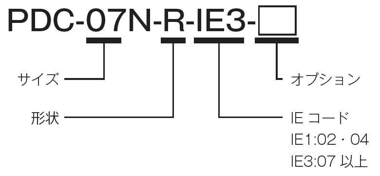
etc.
Generally, “radial” refers to something “radiating outward,” but at Miki Pulley, we use the term to indicate the “perpendicular direction” relative to the center of the shaft on which the coupling is mounted. Furthermore
, in the case of the “Centerflex Coupling,” the bolts used to secure the rubber body or elements that are mounted perpendicular to the center of the shaft are referred to as “R-direction bolts” (where “R” stands for “radial”).For example, radial tires—which use the term in a similar sense—are so named because the metal wires inside the tire are wound perpendicular to the direction of rotation. *The term "axial direction" (parallel direction
) corresponds to the "radial direction" (perpendicular direction).
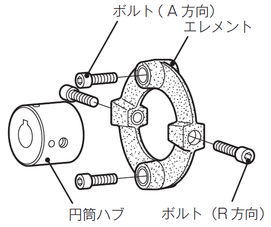
⇒ Please also see the entry for "torsion spring constant."
A radian is a unit of angle in the radians system. In the International System of Units (SI), the angle (plane angle) is defined as a derived SI unit with the proper name "radian.
" You might wonder, "Isn’t an angle measured in 'degrees'? Isn’t one full rotation 360 degrees?" And when we think of a right angle, we instinctively say "90 degrees"—is that wrong? It
isn’t wrong, but it isn’t entirely accurate.The reason one full rotation is 360 degrees is that the number is similar to the 365 days in a year; in fact, it is said to be based on the number of days in a year. This is called the “degree system,” where one division of a circle divided into 360 equal parts is defined as 1 degree. Long ago, people roughly estimated that a year was about 360 days, so defining one full rotation as 360 degrees based on that is not strictly accurate.
As the use of this unit system led to increasing inconveniences, a new concept emerged to replace the degree system. This is the “radian system,” which, as the name suggests, expresses angles in terms of the length of a circular arc (a segment of the circumference).
However, using “degrees” as the unit of angle here would be meaningless, so it was decided to use the term “radians,” represented by the unit [rad]. Furthermore, for a circle with a radius of 1, the length of the arc corresponding to an angle of 1 radian was defined as 1. With this definition, anyone in the world can use it as a well-founded, common standard.
In the Miki Pulley catalog, the specifications for couplings include a "torsional spring constant." This value represents the torque required to twist the coupling in the rotational direction and the resulting angle of deformation; it indicates the stiffness in the torsional direction and is expressed in [N·m/rad].
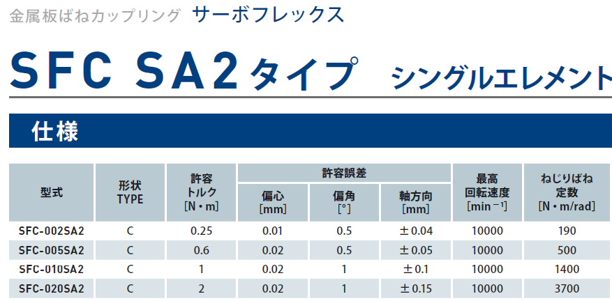
Earlier, I mentioned that for a circle with a radius of 1, the length of an arc corresponding to an angle of 1 radian is set to 1. So, if we set the length of the arc to the circumference of the circle—that is, one full circle—how many radians would that be?
Since the circumference of a circle is equal to the diameter multiplied by pi (π), the circumference of a circle with a radius of 1 is 2π.
Therefore, the circumference is equal to 2π radians.
Since one full circle is 360 degrees, the relationship between the degree system and the radian system is as follows:
360 degrees = 2π radians. This
relationship is very important, so it’s useful to remember it.
As shown above, the length of an arc can be found simply by multiplying the radius and the angle. Furthermore, the area can be easily calculated using the radius and the arc length. Moreover, using radians allows us to apply calculus. In this way, the radian system is a very useful concept not only in mathematics but also in physics and mechanics.
ri
Unlike flexible couplings (flexible shaft couplings), these couplings are designed without elements that accommodate misalignment between the two shafts.
At Miki Pulley, we offer the "Servo Rigid" as a
rigid coupling.Since there are no flexible sections, it can transmit high torque. In other words
, it has the advantage of a very high torsional spring constant. Consequently, compared to a flexible coupling transmitting the same torque, the outer diameter can be made smaller, making it possible to reduce the moment of inertia.
However, the alignment of the two shafts must be performed with the highest possible precision.
While most of Miki Pulley’s “couplings” are flexible couplings, we also offer the rigid coupling “Servo Rigid” to suit your specific applications. Please consider the advantages of each type to select the optimal coupling for your needs.

re
This refers to metals with low production volumes. There is no specific metal
officially designated as a "rare metal," such as nickel or manganese. There are approximately 50 types of rare metal elements, and "rare metals" is a general term for them. In
Japan, rare metals are defined as those that are scarce and for which securing a stable supply is critical.
The reason for their low production volume is, of course, that their natural reserves are limited, but it is also because extraction is difficult from both an economic and technical standpoint. Furthermore
, depending on the type of metal, some can be extracted from only a single producing country, leading to issues such as that country imposing restrictions. There are also problems inherent to the producing countries themselves. Many are located in politically unstable regions such as Central and South America and Africa—that is, countries plagued by constant conflict.
Rare metals include lithium, magnesium, chromium, cobalt, nickel, titanium, manganese, molybdenum, antimony, and tungsten.Furthermore, among rare metals, 17 elements—including gold and silver—are referred to as “rare earth elements.” In contrast, metals with
high production volumes, such as iron, lead, zinc, copper, tin, and aluminum, are called “base metals.” In any case
, since Japan imports nearly all of its base metals and rare metals, ensuring a stable supply is a critical challenge. In particular
, 90% of rare metals are produced in China.
However, the problem is not limited to rare metals.According to the Agency for Natural Resources and Energy under the Ministry of Economy, Trade and Industry, Japan’s energy self-sufficiency rate is low—ranking around 30th in the world—primarily due to the country’s small land area. In particular
, imports of crude oil from Saudi Arabia and the United Arab Emirates alone account for over 50% of the total. If these countries were to stop exporting to us, the situation would become dire. Furthermore
, Japan imports significant amounts of both natural gas and coal from Australia, with natural gas accounting for over 30% and coal for over 70% of total imports.
Consequently, Japan is actively promoting resource conservation and recycling to minimize resource use, while also advancing the development of alternative materials. Furthermore
, as part of its energy policy for 2030, the country has established
a basic framework known as “3E+S.” This approach prioritizes safety (Safety) as the fundamental premise, aiming to simultaneously achieve energy security (Energy Security), economic efficiency (Economic Efficiency), and environmental compatibility (Environment).
For those interested, please visit the Ministry of Economy, Trade and Industry’s website. In any case, the already scarce supply of rare metals is absolutely finite. I believe that simply living with this in mind could change the lifestyle we have previously maintained through wasteful consumption.
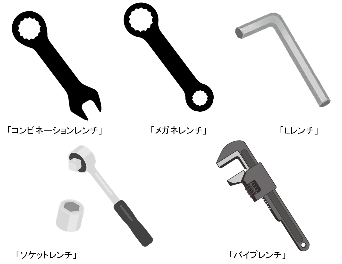
A material that reacts when exposed to light. In industry, it refers to a material used to create protective coatings. The term
derives from the English word "resist," meaning "to resist." Incidentally, the French word "résistance" has the same meaning. It gained attention
in 2019 when export controls to South Korea were tightened.
For example, semiconductor resist is applied to integrated circuit substrates (the common green boards) so that the areas exposed to light harden while the unexposed areas remain soluble. By removing the soluble material, patterns such as circuits can be transferred onto the surface of the semiconductor. This type of semiconductor resist
that reacts when exposed to light is called “photoresist,” and Japanese technology holds a high global market share in this field.
Here, a semiconductor is a material that lies between a “conductor,” which conducts electricity, and an “insulator,” which does not. Because its resistivity changes with temperature, it can be used to control electricity. Integrated circuits are created by attaching components such as transistors, capacitors, and resistors to the surface of these semiconductors.
However, because it is impossible to physically attach these individual components to extremely small semiconductors, engineers instead transfer the circuit patterns onto the semiconductor to achieve the same functionality.
To create a protective layer that shields the circuit areas intended to remain after the transfer process, photoresist—which hardens when exposed to light—is used.
Dyeing is a similar technique. When applying dye to a fabric, a paste is brushed onto the areas where the pattern is to remain undyed. After dyeing, the paste is washed away, revealing a beautifully colored pattern. Semiconductor resist serves the same function as this paste.
At Miki Pulley, photoresist is used in products such as "control panels for DC motors." For reference
, photoresist is listed on the export control list; however, since the quantities used in our products mentioned above do not meet the thresholds for export control, they are classified as "non-applicable" in the "Determination of Applicability" document.
⇒ Please also see the entry for "spanner." ⇒ Please also
refer to the technical document "Shapes and Dimensions of Hexagonal Wrenches (Hex Wrenches/L-Wrenches/Hex Wrenches)."
A tool used to turn nuts and bolts. "Wrench" is considered American English, while "spanner" is British English. In
Japan, both terms are used, though "wrench" seems to be more commonly used as a product name.
One tool closely related to Miki Pulley products is the “torque wrench.” At least in my circle, no one calls it a “torque spanner.” That’s how widely the term “torque wrench” has become established. Also
, while the JIS standard refers to a “hex wrench” as a “hexagonal bar spanner,” it seems almost no one actually calls it that.Although this is the official name under the Japanese Industrial Standards, for some reason, "hex wrench" and "L-wrench" have become more widely accepted.
I believe this is because the term "L-wrench" derives from its L-shape, making it easy to remember and ensuring a common understanding among everyone.
Since “wrench” and “spanner” are essentially the same thing—the difference lies only in whether it’s American or British English—it’s no wonder the terms are used interchangeably in Japan. Amid
this confusion, we’ve even seen the emergence of something called a “spanner wrench.”It would be one thing to use just one of the names—"wrench" or "spanner"—but to use both? This "spanner wrench" features both a spanner and a wrench on either end, and could be considered a general term for tools like "combination wrenches" or "open-end wrenches." Depending on the model, some have hook-like shapes designed to be hooked into a groove and rotated, among other variations.
In addition to the hex wrenches and spanner wrenches mentioned earlier, there are various other names for “wrenches,” so I’ll introduce them here.This diversity stems from
the fact that wrenches, originally designed to turn nuts and bolts, have evolved for a wide range of applications. Examples
include “box wrenches,” “monkey wrenches,” “torque wrenches,” “pipe wrenches,” “socket wrenches,” “ratchet wrenches,” “combination wrenches,” “impact wrenches,” and “cross wrenches.”
Image
R
⇒ Please also refer to the technical document “Shapes and Dimensions of Hex Socket Set Screws.” ⇒ Please also
refer to the technical document “How to Use Hex Socket Set Screws.”
These are set screws with a hexagonal socket. A "set screw" is a type of screw that uses its tip to lock the movement between mechanical components. The "hexagonal socket
" referred to here does not mean that the tip of the screw itself is hexagonal; rather, it refers to the shape of the part where the wrench used to secure this set screw fits.

The tip shapes of hex socket set screws include "flat tip," "pointed tip," "cylindrical tip," and "recessed tip." Since the
tip of this screw comes into direct contact with the shaft (and in some cases, the key), the tip shape is an important consideration.
Generally, the "recessed tip" appears to be the most commonly used. Where the "recessed tip" contacts the shaft, a circular indentation remains, as shown in the figure. If the indentation forms a continuous circular shape, it indicates that the entire surface of the recessed tip is making contact, resulting in strong holding force
. In the case of a poor example, it is likely that the hex socket set screw is not tightened sufficiently, or that the shaft diameter is incorrect (the set screw size does not match the shaft diameter).

Typically, for hex socket set screws, a size slightly smaller than the key width is used. For example, if the key width is 10 mm, an M8 set screw would be used. If a key is not used
, the shaft can be slightly flattened (a process known as a D-cut) so that the entire tip of the screw contacts the surface, thereby increasing the holding force.
Regarding the number of set screws, two is the most common choice. While it is said that two set screws provide stronger holding power than one, the holding power does not simply double.
When using two set screws, an angle of 90 degrees is most common. This is also to prevent the set screws from colliding with each other. Therefore, when using larger set screws, it is necessary to space them further apart, such as at a 120-degree angle.
Furthermore, holding force varies depending on the shaft material and other factors, so it is necessary to select the optimal configuration based on a combination of various conditions, such as shaft diameter and material, set screw size and length, and installation angle. Of course, proper torque control is also crucial.
Although set screws are often used in conjunction with key fastenings, they can loosen on shafts subject to particularly high vibration or continuous vibration. If this happens, the set screw can fly out of the rotating shaft at tremendous speed, posing a serious danger. Furthermore
, play between the key and the keyway can increase, leading to the key shifting and falling out, or the keyway becoming damaged. As you can see
, simply a loose set screw can lead to a serious situation.Customers purchasing Miki Pulley couplings with keyways under the "Standard Bore Specification" are asked to exercise caution when handling the set screws.
⇒ Please also refer to the technical document "List of Standards for Shapes and Dimensions of Hex Socket Head Cap Screws."
These are bolts with a hexagonal socket head. When tightening
the bolt, use a hexagonal wrench that fits the socket.
Hex socket bolts are one of the most commonly used components in Miki Pulley products. In
various types of couplings, they are referred to by names such as clamp bolts or A/R direction bolts. They are also frequently
used to secure Miki Pulley products to the base of your machinery.
Hex socket bolts must be tightened using a torque wrench or torque driver, and it is essential to manage the tightening torque according to the bolt’s strength class.
If the bolts are not tightened to the proper torque, they will loosen.
Please note that this can occur whether the torque is above or below the proper value.
Furthermore, regarding the hex socket bolts used in Miki Pulley’s “couplings,” some products feature “special surface treatments or anti-loosening measures applied to the bolts.” Therefore, please exercise extreme caution when handling them.
By the way, have you noticed that the English translation for “hex socket bolts” is “screw” rather than “bolt”?
However, “hex bolts” are translated as “bolt.” In Japanese, they are all referred to as “bolts,
” but in English, there is a distinction between “bolts” and “screws” due to differences in usage.
This is generally because hex bolts are used in conjunction with nuts. Therefore
, items used with nuts are called "bolts," while those not used with nuts are called "screws." A
typical example is the reamer bolt used in the Servoflex Coupling (SFS Model). In
this case, customers secure the reamer bolt using a nut.
⇒ Please also refer to the technical document "Shapes and Dimensions of Hex Bolts."
A general term for bolts with a hexagonal head. When tightening these bolts, use a wrench with a head shape that fits the hexagonal head. Hex
bolts are used in various Miki Pulley products; for example, in the "Mechanical Shaft Lock/Posilock" series, there are models available that use hex bolts for the clamping bolts.
Additionally, hex bolts are used as pressure bolts in the friction-locking hubs of the "Servoflex Coupling."
"Hex socket bolts" are often used alongside hex bolts, but these require a hex wrench to tighten. As a result, hex socket bolts require significantly more space for tightening
. Therefore, if space is limited, it is recommended to choose the hex bolt type.