日本語
日本語 English
 Deutsch
 中文
中文 한국어
한국어


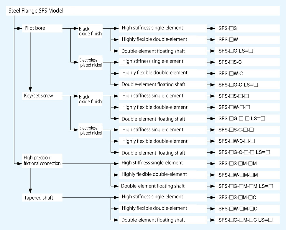
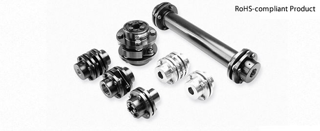
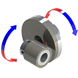
SFS Models

![]()
SFS-□S Types
[Specifications]
| Model | Rated torque[N・m] | Misalignment | Max. rotation speed[min-1] | Torsional stiffness[N・m/rad] | Axial stiffness[N/mm] | Moment of inertia[kg・m2] | Mass[kg] | |
|---|---|---|---|---|---|---|---|---|
| Angular[°] | Axial[mm] | |||||||
| SFS-05S | 20 | 1 | ±0.6 | 25000 | 16000 | 43 | 0.11×10⁻³ | 0.30 |
| SFS-06S | 40 | 1 | ±0.8 | 20000 | 29000 | 45 | 0.30×10⁻³ | 0.50 |
| SFS-08S | 80 | 1 | ±1.0 | 17000 | 83000 | 60 | 0.87×10⁻³ | 1.00 |
| SFS-09S | 180 | 1 | ±1.2 | 15000 | 170000 | 122 | 1.60×10⁻³ | 1.40 |
| SFS-10S | 250 | 1 | ±1.4 | 13000 | 250000 | 160 | 2.60×10⁻³ | 2.10 |
| SFS-12S | 450 | 1 | ±1.6 | 11000 | 430000 | 197 | 6.50×10⁻³ | 3.40 |
| SFS-14S | 800 | 1 | ±1.8 | 9500 | 780000 | 313 | 9.90×10⁻³ | 4.90 |
*Max. rotation speed does not take into account dynamic balance.
*The moment of inertia and mass are measured for the maximum bore diameter.
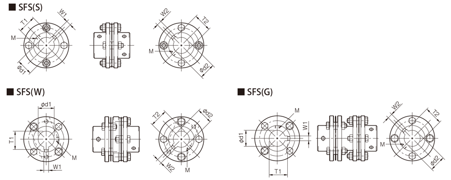
[Dimensions]

| Model | d1・d2 | D | N | L | LF | S | F | K | M | ||
|---|---|---|---|---|---|---|---|---|---|---|---|
| Pilot bore | Min. | Max. | |||||||||
| SFS-05S | 7 | 8 | 20 | 56 | 32 | 45 | 20 | 5 | 11 | 24 | 4-M5×22 |
| SFS-06S | 7 | 8 | 25 | 68 | 40 | 56 | 25 | 6 | 10 | 30 | 4-M6×25 |
| SFS-08S | 10 | 11 | 35 | 82 | 54 | 66 | 30 | 6 | 11 | 38 | 4-M6×29 |
| SFS-09S | 10 | 11 | 38 | 94 | 58 | 68 | 30 | 8 | 21 | 42 | 4-M8×36 |
| SFS-10S | 15 | 16 | 42 | 104 | 68 | 80 | 35 | 10 | 16 | 48 | 4-M8×36 |
| SFS-12S | 18 | 19 | 50 | 126 | 78 | 91 | 40 | 11 | 23 | 54 | 4-M10×45 |
| SFS-14S | 20 | 22 | 60 | 144 | 88 | 102 | 45 | 12 | 31 | 61 | 4-M12×54 |
*Pilot bores are to be drilled into the part.
*The nominal diameter of the reamer bolt M is equal to the quantity minus the nominal diameter of the screw threads times the nominal length.
[Standard bore diameter]
| Model | Standard bore diameter d1・d2 [mm] | |||||||||||||||||||||||||||
|---|---|---|---|---|---|---|---|---|---|---|---|---|---|---|---|---|---|---|---|---|---|---|---|---|---|---|---|---|
| 8 | 9 | 10 | 11 | 12 | 14 | 15 | 16 | 17 | 18 | 19 | 20 | 22 | 24 | 25 | 28 | 30 | 32 | 35 | 38 | 40 | 42 | 45 | 48 | 50 | 55 | 56 | 60 | |
| SFS-05S | ● | ● | ● | ● | ● | ● | ● | ● | ● | ● | ● | ● | ||||||||||||||||
| SFS-06S | ● | ● | ● | ● | ● | ● | ● | ● | ● | ● | ● | ● | ● | ● | ● | |||||||||||||
| SFS-08S | ● | ● | ● | ● | ● | ● | ● | ● | ● | ● | ● | ● | ● | ● | ● | ● | ||||||||||||
| SFS-09S | ● | ● | ● | ● | ● | ● | ● | ● | ● | ● | ● | ● | ● | ● | ● | ● | ● | |||||||||||
| SFS-10S | ● | ● | ● | ● | ● | ● | ● | ● | ● | ● | ● | ● | ● | ● | ● | |||||||||||||
| SFS-12S | ● | ● | ● | ● | ● | ● | ● | ● | ● | ● | ● | ● | ● | ● | ● | |||||||||||||
| SFS-14S | ● | ● | ● | ● | ● | ● | ● | ● | ● | ● | ● | ● | ● | ● | ● | ● | ||||||||||||
* Bore diameters marked with ● are supported as standard bore diameter. See the standard hole-drilling standards for information.
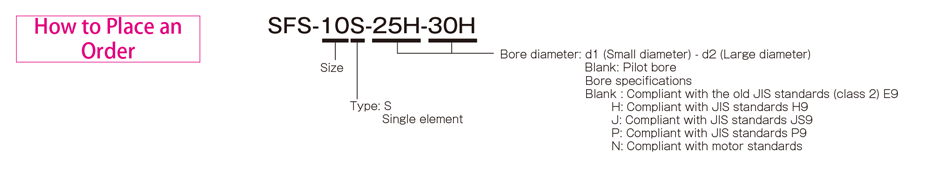
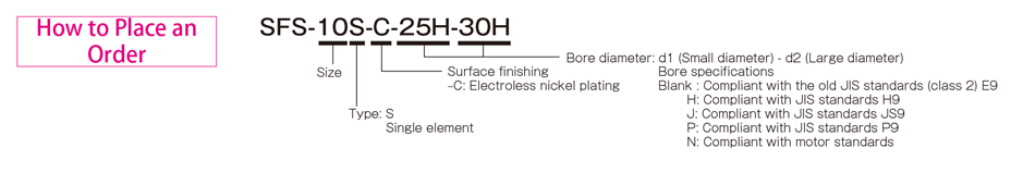
【Standard Hole-Drilling Standards】
| Models compliant with the old JIS standard (class 2) JIS B 1301 1959 | Models compliant with the new JIS standard (H9) JIS B 1301 1996 | Models compliant with the new JIS standard (JS9) JIS B 1301 1996 | ||||||||||||
|---|---|---|---|---|---|---|---|---|---|---|---|---|---|---|
| Nominal bore diameter | Bore diameter(d1・d2) | Keyway height(W1・W2) | Keyway height(T1・T2) | Set screw hole(M) | Nominal bore diameter | Bore diameter(d1・d2) | Keyway height(W1・W2) | Keyway height(T1・T2) | Set screw hole(M) | Nominal bore diameter | Bore diameter(d1・d2) | Keyway height(W1・W2) | Keyway height(T1・T2) | Set screw hole(M) |
| ToleranceH7,H8 | ToleranceE9 | - | - | ToleranceH7,H8 | ToleranceH9 | - | - | ToleranceH7,H8 | ToleranceJS9 | - | - | |||
| 8 | 8+0.0220 | - | - | 2-M4 | 8H | 8+0.0220 | 3+0.0250 | 9.4+0.30 | 2-M4 | 8J | 8+0.0220 | 3±0.0125 | 9.4+0.30 | 2-M4 |
| 9 | 9+0.0220 | - | - | 2-M4 | 9H | 9+0.0220 | 3+0.0250 | 10.4+0.30 | 2-M4 | 9J | 9+0.0220 | 3±0.0125 | 10.4+0.30 | 2-M4 |
| 10 | 10+0.0220 | - | - | 2-M4 | 10H | 10+0.0220 | 3+0.0250 | 11.4+0.30 | 2-M4 | 10J | 10+0.0220 | 3±0.0125 | 11.4+0.30 | 2-M4 |
| 11 | 11+0.0180 | - | - | 2-M4 | 11H | 11+0.0180 | 4+0.0300 | 12.8+0.30 | 2-M4 | 11J | 11+0.0180 | 4±0.0150 | 12.8+0.30 | 2-M4 |
| 12 | 12+0.0180 | 4+0.050+0.020 | 13.5+0.30 | 2-M4 | 12H | 12+0.0180 | 4+0.0300 | 13.8+0.30 | 2-M4 | 12J | 12+0.0180 | 4±0.0150 | 13.8+0.30 | 2-M4 |
| 14 | 14+0.0180 | 5+0.050+0.020 | 16+0.30 | 2-M4 | 14H | 14+0.0180 | 5+0.0300 | 16.3+0.30 | 2-M4 | 14J | 14+0.0180 | 5±0.0150 | 16.3+0.30 | 2-M4 |
| 15 | 15+0.0180 | 5+0.050+0.020 | 17+0.30 | 2-M4 | 15H | 15+0.0180 | 5+0.0300 | 17.3+0.30 | 2-M4 | 15J | 15+0.0180 | 5±0.0150 | 17.3+0.30 | 2-M4 |
| 16 | 16+0.0180 | 5+0.050+0.020 | 18+0.30 | 2-M4 | 16H | 16+0.0180 | 5+0.0300 | 18.3+0.30 | 2-M4 | 16J | 16+0.0180 | 5±0.0150 | 18.3+0.30 | 2-M4 |
| 17 | 17+0.0180 | 5+0.050+0.020 | 19+0.30 | 2-M4 | 17H | 17+0.0180 | 5+0.0300 | 19.3+0.30 | 2-M4 | 17J | 17+0.0180 | 5±0.0150 | 19.3+0.30 | 2-M4 |
| 18 | 18+0.0180 | 5+0.050+0.020 | 20+0.30 | 2-M4 | 18H | 18+0.0180 | 6+0.0300 | 20.8+0.30 | 2-M5 | 18J | 18+0.0180 | 6±0.0150 | 20.8+0.30 | 2-M5 |
| 19 | 19+0.0210 | 5+0.050+0.020 | 21+0.30 | 2-M4 | 19H | 19+0.0210 | 6+0.0300 | 21.8+0.30 | 2-M5 | 19J | 19+0.0210 | 6±0.0150 | 21.8+0.30 | 2-M5 |
| 20 | 20+0.0210 | 5+0.050+0.020 | 22+0.30 | 2-M4 | 20H | 20+0.0210 | 6+0.0300 | 22.8+0.30 | 2-M5 | 20J | 20+0.0210 | 6±0.0150 | 22.8+0.30 | 2-M5 |
| 22 | 22+0.0210 | 7+0.061+0.025 | 25+0.30 | 2-M6 | 22H | 22+0.0210 | 6+0.0300 | 24.8+0.30 | 2-M5 | 22J | 22+0.0210 | 6±0.0150 | 24.8+0.30 | 2-M5 |
| 24 | 24+0.0210 | 7+0.061+0.025 | 27+0.30 | 2-M6 | 24H | 24+0.0210 | 8+0.0360 | 27.3+0.30 | 2-M6 | 24J | 24+0.0210 | 8±0.0180 | 27.3+0.30 | 2-M6 |
| 25 | 25+0.0210 | 7+0.061+0.025 | 28+0.30 | 2-M6 | 25H | 25+0.0210 | 8+0.0360 | 28.3+0.30 | 2-M6 | 25J | 25+0.0210 | 8±0.0180 | 28.3+0.30 | 2-M6 |
| 28 | 28+0.0210 | 7+0.061+0.025 | 31+0.30 | 2-M6 | 28H | 28+0.0210 | 8+0.0360 | 31.3+0.30 | 2-M6 | 28J | 28+0.0210 | 8±0.0180 | 31.3+0.30 | 2-M6 |
| 30 | 30+0.0210 | 7+0.061+0.025 | 33+0.30 | 2-M6 | 30H | 30+0.0210 | 8+0.0360 | 33.3+0.30 | 2-M6 | 30J | 30+0.0210 | 8±0.0180 | 33.3+0.30 | 2-M6 |
| 32 | 32+0.0250 | 10+0.061+0.025 | 35.5+0.30 | 2-M8 | 32H | 32+0.0250 | 10+0.0360 | 35.3+0.30 | 2-M8 | 32J | 32+0.0250 | 10±0.0180 | 35.3+0.30 | 2-M8 |
| 35 | 35+0.0250 | 10+0.061+0.025 | 38.5+0.30 | 2-M8 | 35H | 35+0.0250 | 10+0.0360 | 38.3+0.30 | 2-M8 | 35J | 35+0.0250 | 10±0.0180 | 38.3+0.30 | 2-M8 |
| 38 | 38+0.0250 | 10+0.061+0.025 | 41.5+0.30 | 2-M8 | 38H | 38+0.0250 | 10+0.0360 | 41.3+0.30 | 2-M8 | 38J | 38+0.0250 | 10±0.0180 | 41.3+0.30 | 2-M8 |
| 40 | 40+0.0250 | 10+0.061+0.025 | 43.5+0.30 | 2-M8 | 40H | 40+0.0250 | 12+0.0430 | 43.3+0.30 | 2-M8 | 40J | 40+0.0250 | 12±0.0215 | 43.3+0.30 | 2-M8 |
| 42 | 42+0.0250 | 12+0.075+0.032 | 45.5+0.30 | 2-M8 | 42H | 42+0.0250 | 12+0.0430 | 45.3+0.30 | 2-M8 | 42J | 42+0.0250 | 12±0.0215 | 45.3+0.30 | 2-M8 |
| 45 | 45+0.0250 | 12+0.075+0.032 | 48.5+0.30 | 2-M8 | 45H | 45+0.0250 | 14+0.0430 | 48.8+0.30 | 2-M10 | 45J | 45+0.0250 | 14±0.0215 | 48.8+0.30 | 2-M10 |
| 48 | 48+0.0250 | 12+0.075+0.032 | 51.5+0.30 | 2-M8 | 48H | 48+0.0250 | 14+0.0430 | 51.8+0.30 | 2-M10 | 48J | 48+0.0250 | 14±0.0215 | 51.8+0.30 | 2-M10 |
| 50 | 50+0.0250 | 12+0.075+0.032 | 53.5+0.30 | 2-M8 | 50H | 50+0.0250 | 14+0.0430 | 53.8+0.30 | 2-M10 | 50J | 50+0.0250 | 14±0.0215 | 53.8+0.30 | 2-M10 |
| 55 | 55+0.0300 | 15+0.075+0.032 | 60+0.30 | 2-M10 | 55H | 55+0.0300 | 16+0.0430 | 59.3+0.30 | 2-M10 | 55J | 55+0.0300 | 16±0.0215 | 59.3+0.30 | 2-M10 |
| 56 | 56+0.0300 | 15+0.075+0.032 | 61+0.30 | 2-M10 | 56H | 56+0.0300 | 16+0.0430 | 60.3+0.30 | 2-M10 | 56J | 56+0.0300 | 16±0.0215 | 60.3+0.30 | 2-M10 |
| 60 | 60+0.0300 | 15+0.075+0.032 | 65+0.30 | 2-M10 | 60H | 60+0.0300 | 18+0.0430 | 64.4+0.30 | 2-M10 | 60J | 60+0.0300 | 18±0.0215 | 64.4+0.30 | 2-M10 |
| Models compliant with the new JIS standard (P9) JIS B 1301 1996 | Models compliant with the motor standard JIS C 4210 2001 | ||||||||
|---|---|---|---|---|---|---|---|---|---|
| Nominal bore diameter | Bore diameter(d1・d2) | Keyway width(W1・W2) | Keyway height(T1・T2) | Set screw hole(M) | Nominal bore diameter | Bore diameter(d1・d2) | Keyway width(W1・W2) | Keyway height(T1・T2) | Set screw hole(M) |
| ToleranceH7,H8 | ToleranceP9 | + 0.30 0 | - | - | ToleranceG7,F7 | ToleranceH9 | - | ||
| 8P | 8 +0.022 | 3-0.006-0.031 | 9.4+0.30 | 2-M4 | - | - | - | - | - |
| 9P | 9 +0.022 | 3-0.006-0.031 | 10.4+0.30 | 2-M4 | - | - | - | - | - |
| 10P | 10 +0.022 | 3-0.006-0.031 | 11.4+0.30 | 2-M4 | - | - | - | - | - |
| 11P | 11+0.018 | 4-0.042-0.012 | 12.8+0.30 | 2-M4 | - | - | - | - | - |
| 12P | 12 +0.018 | 4-0.042-0.012 | 13.8+0.30 | 2-M4 | - | - | - | - | - |
| 14P | 14+0.018 | 5-0.042-0.012 | 16.3+0.30 | 2-M4 | 14N | 14+0.024+0.006 | 5+0.030 | 16.3+0.30 | 2-M4 |
| 15P | 15+0.018 | 5-0.042-0.012 | 17.3+0.30 | 2-M4 | - | - | - | - | - |
| 16P | 16+0.018 | 5-0.042-0.012 | 18.3+0.30 | 2-M4 | - | - | - | - | - |
| 17P | 17+0.018 | 5-0.042-0.012 | 19.3+0.30 | 2-M4 | - | - | - | - | - |
| 18P | 18+0.018 | 6-0.042-0.012 | 20.8+0.30 | 2-M5 | - | - | - | - | - |
| 19P | 19 +0.021 | 6-0.042-0.012 | 21.8+0.30 | 2-M5 | 19N | 19+0.028+0.007 | 6+0.030 | 21.8+0.30 | 2-M5 |
| 20P | 20 +0.021 | 6-0.042-0.012 | 22.8+0.30 | 2-M5 | - | - | - | - | - |
| 22P | 22 +0.021 | 6-0.042-0.012 | 24.8+0.30 | 2-M5 | - | - | - | - | - |
| 24P | 24 +0.021 | 8-0.051-0.015 | 27.3+0.30 | 2-M6 | 24N | 24+0.028+0.007 | 8+0.036 | 27.3+0.30 | 2-M6 |
| 25P | 25 +0.021 | 8-0.051-0.015 | 28.3+0.30 | 2-M6 | - | - | - | - | - |
| 28P | 28 +0.021 | 8-0.051-0.015 | 31.3+0.30 | 2-M6 | 28N | 28+0.028+0.007 | 8+0.036 | 31.3+0.30 | 2-M6 |
| 30P | 30 +0.021 | 8-0.051-0.015 | 33.3+0.30 | 2-M6 | - | - | - | - | - |
| 32P | 32 +0.025 | 10-0.051-0.015 | 35.3+0.30 | 2-M8 | - | - | - | ||
| 35P | 35 +0.025 | 10-0.051-0.015 | 38.3+0.30 | 2-M8 | - | - | - | - | |
| 38P | 38 +0.025 | 10-0.051-0.015 | 41.3+0.30 | 2-M8 | 38N | 38+0.050+0.025 | 10+0.036 | 41.3+0.30 | 2-M8 |
| 40P | 40 +0.025 | 12-0.061-0.018 | 43.3+0.30 | 2-M8 | - | - | - | - | - |
| 42P | 42 +0.025 | 12-0.061-0.018 | 45.3+0.30 | 2-M8 | 42N | 42+0.050+0.025 | 12+0.043 | 45.3+0.30 | 2-M8 |
| 45P | 45 +0.025 | 14-0.061-0.018 | 48.8+0.30 | 2-M10 | - | - | - | - | - |
| 48P | 48 +0.025 | 14-0.061-0.018 | 51.8+0.30 | 2-M10 | 48N | 48+0.050+0.025 | 14+0.043 | 51.8+0.30 | 2-M10 |
| 50P | 50 +0.025 | 14-0.061-0.018 | 53.8+0.30 | 2-M10 | - | - | - | - | - |
| 55P | 55 +0.030 | 16-0.061-0.018 | 59.3+0.30 | 2-M10 | 55N | 55+0.060+0.030 | 16+0.043 | 59.3+0.30 | 2-M10 |
| 56P | 56 +0.030 | 16-0.061-0.018 | 60.3+0.30 | 2-M10 | - | - | - | - | - |
| 60P | 60 +0.030 | 18-0.061-0.018 | 64.4+0.30 | 2-M10 | 60N | 60+0.060+0.030 | 18+0.043 | 64.4+0.30 | 2-M10 |
※Positions of set screws and keyways are not on the same plane.
※Set screws are included with the product.
※Positioning precision for keyway milling is determined by sight.
※Contact Miki Pulley when the keyway requires a positioning precision for a particular flange hub.
※Consult the technical documentation at the end of this volume for standard dimensions for bore drilling other than those given here.
【Set screw position】
| Model | Distance from edge [mm] |
|---|---|
| SFS-05 | 7 |
| SFS-06 | 9 |
| SFS-08 | 10 |
| SFS-09 | 10 |
| SFS-10 | 12 |
| SFS-12 | 12 |
| SFS-14 | 15 |
SFS-□S (C) Types
[Specifications]
| Model | Rated torque[N・m] | Misalignment | Max. rotation speed[min-1] | Torsional stiffness[N・m/rad] | Axial stiffness[N/mm] | Moment of inertia[kg・m2] | Mass[kg] | |
|---|---|---|---|---|---|---|---|---|
| Angular[°] | Axial[mm] | |||||||
| SFS-05S-C | 15 | 1 | ±0.6 | 25000 | 16000 | 43 | 0.11×10⁻³ | 0.30 |
| SFS-06S-C | 30 | 1 | ±0.8 | 20000 | 29000 | 45 | 0.30×10⁻³ | 0.50 |
| SFS-08S-C | 60 | 1 | ±1.0 | 17000 | 83000 | 60 | 0.87×10⁻³ | 1.00 |
| SFS-09S-C | 135 | 1 | ±1.2 | 15000 | 170000 | 122 | 1.60×10⁻³ | 1.40 |
| SFS-10S-C | 190 | 1 | ±1.4 | 13000 | 250000 | 160 | 2.60×10⁻³ | 2.10 |
| SFS-12S-C | 340 | 1 | ±1.6 | 11000 | 430000 | 197 | 6.50×10⁻³ | 3.40 |
| SFS-14S-C | 600 | 1 | ±1.8 | 9500 | 780000 | 313 | 9.90×10⁻³ | 4.90 |
*Max. rotation speed does not take into account dynamic balance.
*The moment of inertia and mass are measured for the maximum bore diameter.
[Dimensions]
| Model | d1・d2 | D | N | L | LF | S | F | K | M | |
|---|---|---|---|---|---|---|---|---|---|---|
| Min. | Max. | |||||||||
| SFS-05S-C | 8 | 20 | 56 | 32 | 45 | 20 | 5 | 11 | 24 | 4-M5×22 |
| SFS-06S-C | 8 | 25 | 68 | 40 | 56 | 25 | 6 | 10 | 30 | 4-M6×25 |
| SFS-08S-C | 11 | 35 | 82 | 54 | 66 | 30 | 6 | 11 | 38 | 4-M6×29 |
| SFS-09S-C | 11 | 38 | 94 | 58 | 68 | 30 | 8 | 21 | 42 | 4-M8×36 |
| SFS-10S-C | 16 | 42 | 104 | 68 | 80 | 35 | 10 | 16 | 48 | 4-M8×36 |
| SFS-12S-C | 19 | 50 | 126 | 78 | 91 | 40 | 11 | 23 | 54 | 4-M10×45 |
| SFS-14S-C | 22 | 60 | 144 | 88 | 102 | 45 | 12 | 31 | 61 | 4-M12×54 |
*The nominal diameter of the reamer bolt M is equal to the quantity minus the nominal diameter of the screw threads times the nominal length.
[Standard bore diameter]
| Model | Standard bore diameter d1・d2 [mm] | |||||||||||||||||||||||||||
|---|---|---|---|---|---|---|---|---|---|---|---|---|---|---|---|---|---|---|---|---|---|---|---|---|---|---|---|---|
| 8 | 9 | 10 | 11 | 12 | 14 | 15 | 16 | 17 | 18 | 19 | 20 | 22 | 24 | 25 | 28 | 30 | 32 | 35 | 38 | 40 | 42 | 45 | 48 | 50 | 55 | 56 | 60 | |
| SFS-05S-C | ● | ● | ● | ● | ● | ● | ● | ● | ● | ● | ● | ● | ||||||||||||||||
| SFS-06S-C | ● | ● | ● | ● | ● | ● | ● | ● | ● | ● | ● | ● | ● | ● | ● | |||||||||||||
| SFS-08S-C | ● | ● | ● | ● | ● | ● | ● | ● | ● | ● | ● | ● | ● | ● | ● | ● | ||||||||||||
| SFS-09S-C | ● | ● | ● | ● | ● | ● | ● | ● | ● | ● | ● | ● | ● | ● | ● | ● | ● | |||||||||||
| SFS-10S-C | ● | ● | ● | ● | ● | ● | ● | ● | ● | ● | ● | ● | ● | ● | ● | |||||||||||||
| SFS-12S-C | ● | ● | ● | ● | ● | ● | ● | ● | ● | ● | ● | ● | ● | ● | ● | |||||||||||||
| SFS-14S-C | ● | ● | ● | ● | ● | ● | ● | ● | ● | ● | ● | ● | ● | ● | ● | ● | ||||||||||||
* Bore diameters marked with ● are supported as standard bore diameter. See the standard hole-drilling standards for information.
【Standard Hole-Drilling Standards】
| Models compliant with the old JIS standard (class 2) JIS B 1301 1959 | Models compliant with the new JIS standard (H9) JIS B 1301 1996 | Models compliant with the new JIS standard (JS9) JIS B 1301 1996 | ||||||||||||
|---|---|---|---|---|---|---|---|---|---|---|---|---|---|---|
| Nominal bore diameter | Bore diameter(d1・d2) | Keyway height(W1・W2) | Keyway height(T1・T2) | Set screw hole(M) | Nominal bore diameter | Bore diameter(d1・d2) | Keyway height(W1・W2) | Keyway height(T1・T2) | Set screw hole(M) | Nominal bore diameter | Bore diameter(d1・d2) | Keyway height(W1・W2) | Keyway height(T1・T2) | Set screw hole(M) |
| ToleranceH7,H8 | ToleranceE9 | - | - | ToleranceH7,H8 | ToleranceH9 | - | - | ToleranceH7,H8 | ToleranceJS9 | - | - | |||
| 8 | 8+0.0220 | - | - | 2-M4 | 8H | 8+0.0220 | 3+0.0250 | 9.4+0.30 | 2-M4 | 8J | 8+0.0220 | 3±0.0125 | 9.4+0.30 | 2-M4 |
| 9 | 9+0.0220 | - | - | 2-M4 | 9H | 9+0.0220 | 3+0.0250 | 10.4+0.30 | 2-M4 | 9J | 9+0.0220 | 3±0.0125 | 10.4+0.30 | 2-M4 |
| 10 | 10+0.0220 | - | - | 2-M4 | 10H | 10+0.0220 | 3+0.0250 | 11.4+0.30 | 2-M4 | 10J | 10+0.0220 | 3±0.0125 | 11.4+0.30 | 2-M4 |
| 11 | 11+0.0180 | - | - | 2-M4 | 11H | 11+0.0180 | 4+0.0300 | 12.8+0.30 | 2-M4 | 11J | 11+0.0180 | 4±0.0150 | 12.8+0.30 | 2-M4 |
| 12 | 12+0.0180 | 4+0.050+0.020 | 13.5+0.30 | 2-M4 | 12H | 12+0.0180 | 4+0.0300 | 13.8+0.30 | 2-M4 | 12J | 12+0.0180 | 4±0.0150 | 13.8+0.30 | 2-M4 |
| 14 | 14+0.0180 | 5+0.050+0.020 | 16+0.30 | 2-M4 | 14H | 14+0.0180 | 5+0.0300 | 16.3+0.30 | 2-M4 | 14J | 14+0.0180 | 5±0.0150 | 16.3+0.30 | 2-M4 |
| 15 | 15+0.0180 | 5+0.050+0.020 | 17+0.30 | 2-M4 | 15H | 15+0.0180 | 5+0.0300 | 17.3+0.30 | 2-M4 | 15J | 15+0.0180 | 5±0.0150 | 17.3+0.30 | 2-M4 |
| 16 | 16+0.0180 | 5+0.050+0.020 | 18+0.30 | 2-M4 | 16H | 16+0.0180 | 5+0.0300 | 18.3+0.30 | 2-M4 | 16J | 16+0.0180 | 5±0.0150 | 18.3+0.30 | 2-M4 |
| 17 | 17+0.0180 | 5+0.050+0.020 | 19+0.30 | 2-M4 | 17H | 17+0.0180 | 5+0.0300 | 19.3+0.30 | 2-M4 | 17J | 17+0.0180 | 5±0.0150 | 19.3+0.30 | 2-M4 |
| 18 | 18+0.0180 | 5+0.050+0.020 | 20+0.30 | 2-M4 | 18H | 18+0.0180 | 6+0.0300 | 20.8+0.30 | 2-M5 | 18J | 18+0.0180 | 6±0.0150 | 20.8+0.30 | 2-M5 |
| 19 | 19+0.0210 | 5+0.050+0.020 | 21+0.30 | 2-M4 | 19H | 19+0.0210 | 6+0.0300 | 21.8+0.30 | 2-M5 | 19J | 19+0.0210 | 6±0.0150 | 21.8+0.30 | 2-M5 |
| 20 | 20+0.0210 | 5+0.050+0.020 | 22+0.30 | 2-M4 | 20H | 20+0.0210 | 6+0.0300 | 22.8+0.30 | 2-M5 | 20J | 20+0.0210 | 6±0.0150 | 22.8+0.30 | 2-M5 |
| 22 | 22+0.0210 | 7+0.061+0.025 | 25+0.30 | 2-M6 | 22H | 22+0.0210 | 6+0.0300 | 24.8+0.30 | 2-M5 | 22J | 22+0.0210 | 6±0.0150 | 24.8+0.30 | 2-M5 |
| 24 | 24+0.0210 | 7+0.061+0.025 | 27+0.30 | 2-M6 | 24H | 24+0.0210 | 8+0.0360 | 27.3+0.30 | 2-M6 | 24J | 24+0.0210 | 8±0.0180 | 27.3+0.30 | 2-M6 |
| 25 | 25+0.0210 | 7+0.061+0.025 | 28+0.30 | 2-M6 | 25H | 25+0.0210 | 8+0.0360 | 28.3+0.30 | 2-M6 | 25J | 25+0.0210 | 8±0.0180 | 28.3+0.30 | 2-M6 |
| 28 | 28+0.0210 | 7+0.061+0.025 | 31+0.30 | 2-M6 | 28H | 28+0.0210 | 8+0.0360 | 31.3+0.30 | 2-M6 | 28J | 28+0.0210 | 8±0.0180 | 31.3+0.30 | 2-M6 |
| 30 | 30+0.0210 | 7+0.061+0.025 | 33+0.30 | 2-M6 | 30H | 30+0.0210 | 8+0.0360 | 33.3+0.30 | 2-M6 | 30J | 30+0.0210 | 8±0.0180 | 33.3+0.30 | 2-M6 |
| 32 | 32+0.0250 | 10+0.061+0.025 | 35.5+0.30 | 2-M8 | 32H | 32+0.0250 | 10+0.0360 | 35.3+0.30 | 2-M8 | 32J | 32+0.0250 | 10±0.0180 | 35.3+0.30 | 2-M8 |
| 35 | 35+0.0250 | 10+0.061+0.025 | 38.5+0.30 | 2-M8 | 35H | 35+0.0250 | 10+0.0360 | 38.3+0.30 | 2-M8 | 35J | 35+0.0250 | 10±0.0180 | 38.3+0.30 | 2-M8 |
| 38 | 38+0.0250 | 10+0.061+0.025 | 41.5+0.30 | 2-M8 | 38H | 38+0.0250 | 10+0.0360 | 41.3+0.30 | 2-M8 | 38J | 38+0.0250 | 10±0.0180 | 41.3+0.30 | 2-M8 |
| 40 | 40+0.0250 | 10+0.061+0.025 | 43.5+0.30 | 2-M8 | 40H | 40+0.0250 | 12+0.0430 | 43.3+0.30 | 2-M8 | 40J | 40+0.0250 | 12±0.0215 | 43.3+0.30 | 2-M8 |
| 42 | 42+0.0250 | 12+0.075+0.032 | 45.5+0.30 | 2-M8 | 42H | 42+0.0250 | 12+0.0430 | 45.3+0.30 | 2-M8 | 42J | 42+0.0250 | 12±0.0215 | 45.3+0.30 | 2-M8 |
| 45 | 45+0.0250 | 12+0.075+0.032 | 48.5+0.30 | 2-M8 | 45H | 45+0.0250 | 14+0.0430 | 48.8+0.30 | 2-M10 | 45J | 45+0.0250 | 14±0.0215 | 48.8+0.30 | 2-M10 |
| 48 | 48+0.0250 | 12+0.075+0.032 | 51.5+0.30 | 2-M8 | 48H | 48+0.0250 | 14+0.0430 | 51.8+0.30 | 2-M10 | 48J | 48+0.0250 | 14±0.0215 | 51.8+0.30 | 2-M10 |
| 50 | 50+0.0250 | 12+0.075+0.032 | 53.5+0.30 | 2-M8 | 50H | 50+0.0250 | 14+0.0430 | 53.8+0.30 | 2-M10 | 50J | 50+0.0250 | 14±0.0215 | 53.8+0.30 | 2-M10 |
| 55 | 55+0.0300 | 15+0.075+0.032 | 60+0.30 | 2-M10 | 55H | 55+0.0300 | 16+0.0430 | 59.3+0.30 | 2-M10 | 55J | 55+0.0300 | 16±0.0215 | 59.3+0.30 | 2-M10 |
| 56 | 56+0.0300 | 15+0.075+0.032 | 61+0.30 | 2-M10 | 56H | 56+0.0300 | 16+0.0430 | 60.3+0.30 | 2-M10 | 56J | 56+0.0300 | 16±0.0215 | 60.3+0.30 | 2-M10 |
| 60 | 60+0.0300 | 15+0.075+0.032 | 65+0.30 | 2-M10 | 60H | 60+0.0300 | 18+0.0430 | 64.4+0.30 | 2-M10 | 60J | 60+0.0300 | 18±0.0215 | 64.4+0.30 | 2-M10 |
| Models compliant with the new JIS standard (P9) JIS B 1301 1996 | Models compliant with the motor standard JIS C 4210 2001 | ||||||||
|---|---|---|---|---|---|---|---|---|---|
| Nominal bore diameter | Bore diameter(d1・d2) | Keyway width(W1・W2) | Keyway height(T1・T2) | Set screw hole(M) | Nominal bore diameter | Bore diameter(d1・d2) | Keyway width(W1・W2) | Keyway height(T1・T2) | Set screw hole(M) |
| ToleranceH7,H8 | ToleranceP9 | + 0.30 0 | - | - | ToleranceG7,F7 | ToleranceH9 | - | ||
| 8P | 8 +0.022 | 3-0.006-0.031 | 9.4+0.30 | 2-M4 | - | - | - | - | - |
| 9P | 9 +0.022 | 3-0.006-0.031 | 10.4+0.30 | 2-M4 | - | - | - | - | - |
| 10P | 10 +0.022 | 3-0.006-0.031 | 11.4+0.30 | 2-M4 | - | - | - | - | - |
| 11P | 11+0.018 | 4-0.042-0.012 | 12.8+0.30 | 2-M4 | - | - | - | - | - |
| 12P | 12 +0.018 | 4-0.042-0.012 | 13.8+0.30 | 2-M4 | - | - | - | - | - |
| 14P | 14+0.018 | 5-0.042-0.012 | 16.3+0.30 | 2-M4 | 14N | 14+0.024+0.006 | 5+0.030 | 16.3+0.30 | 2-M4 |
| 15P | 15+0.018 | 5-0.042-0.012 | 17.3+0.30 | 2-M4 | - | - | - | - | - |
| 16P | 16+0.018 | 5-0.042-0.012 | 18.3+0.30 | 2-M4 | - | - | - | - | - |
| 17P | 17+0.018 | 5-0.042-0.012 | 19.3+0.30 | 2-M4 | - | - | - | - | - |
| 18P | 18+0.018 | 6-0.042-0.012 | 20.8+0.30 | 2-M5 | - | - | - | - | - |
| 19P | 19 +0.021 | 6-0.042-0.012 | 21.8+0.30 | 2-M5 | 19N | 19+0.028+0.007 | 6+0.030 | 21.8+0.30 | 2-M5 |
| 20P | 20 +0.021 | 6-0.042-0.012 | 22.8+0.30 | 2-M5 | - | - | - | - | - |
| 22P | 22 +0.021 | 6-0.042-0.012 | 24.8+0.30 | 2-M5 | - | - | - | - | - |
| 24P | 24 +0.021 | 8-0.051-0.015 | 27.3+0.30 | 2-M6 | 24N | 24+0.028+0.007 | 8+0.036 | 27.3+0.30 | 2-M6 |
| 25P | 25 +0.021 | 8-0.051-0.015 | 28.3+0.30 | 2-M6 | - | - | - | - | - |
| 28P | 28 +0.021 | 8-0.051-0.015 | 31.3+0.30 | 2-M6 | 28N | 28+0.028+0.007 | 8+0.036 | 31.3+0.30 | 2-M6 |
| 30P | 30 +0.021 | 8-0.051-0.015 | 33.3+0.30 | 2-M6 | - | - | - | - | - |
| 32P | 32 +0.025 | 10-0.051-0.015 | 35.3+0.30 | 2-M8 | - | - | - | ||
| 35P | 35 +0.025 | 10-0.051-0.015 | 38.3+0.30 | 2-M8 | - | - | - | - | |
| 38P | 38 +0.025 | 10-0.051-0.015 | 41.3+0.30 | 2-M8 | 38N | 38+0.050+0.025 | 10+0.036 | 41.3+0.30 | 2-M8 |
| 40P | 40 +0.025 | 12-0.061-0.018 | 43.3+0.30 | 2-M8 | - | - | - | - | - |
| 42P | 42 +0.025 | 12-0.061-0.018 | 45.3+0.30 | 2-M8 | 42N | 42+0.050+0.025 | 12+0.043 | 45.3+0.30 | 2-M8 |
| 45P | 45 +0.025 | 14-0.061-0.018 | 48.8+0.30 | 2-M10 | - | - | - | - | - |
| 48P | 48 +0.025 | 14-0.061-0.018 | 51.8+0.30 | 2-M10 | 48N | 48+0.050+0.025 | 14+0.043 | 51.8+0.30 | 2-M10 |
| 50P | 50 +0.025 | 14-0.061-0.018 | 53.8+0.30 | 2-M10 | - | - | - | - | - |
| 55P | 55 +0.030 | 16-0.061-0.018 | 59.3+0.30 | 2-M10 | 55N | 55+0.060+0.030 | 16+0.043 | 59.3+0.30 | 2-M10 |
| 56P | 56 +0.030 | 16-0.061-0.018 | 60.3+0.30 | 2-M10 | - | - | - | - | - |
| 60P | 60 +0.030 | 18-0.061-0.018 | 64.4+0.30 | 2-M10 | 60N | 60+0.060+0.030 | 18+0.043 | 64.4+0.30 | 2-M10 |
※Positions of set screws and keyways are not on the same plane.
※Set screws are included with the product.
※Positioning precision for keyway milling is determined by sight.
※Contact Miki Pulley when the keyway requires a positioning precision for a particular flange hub.
※Consult the technical documentation at the end of this volume for standard dimensions for bore drilling other than those given here.
【Set screw position】
| Model | Distance from edge [mm] |
|---|---|
| SFS-05 | 7 |
| SFS-06 | 9 |
| SFS-08 | 10 |
| SFS-09 | 10 |
| SFS-10 | 12 |
| SFS-12 | 12 |
| SFS-14 | 15 |
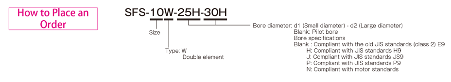
SFS-□W Types
[Specifications]
| Model | Rated torque[N・m] | Misalignment | Max. rotation speed[min-1] | Torsional stiffness[N・m/rad] | Axial stiffness[N/mm] | Moment of inertia[kg・m2] | Mass[kg] | ||
|---|---|---|---|---|---|---|---|---|---|
| Parallel[mm] | Angular[°] | Axial[mm] | |||||||
| SFS-05W | 20 | 0.2 | 1(On one side) | ±1.2 | 10000 | 8000 | 21 | 0.14×10⁻³ | 0.40 |
| SFS-06W | 40 | 0.3 | 1(On one side) | ±1.6 | 8000 | 14000 | 22 | 0.41×10⁻³ | 0.70 |
| SFS-08W | 80 | 0.3 | 1(On one side) | ±2.0 | 6800 | 41000 | 30 | 1.10×10⁻³ | 1.30 |
| SFS-09W | 180 | 0.5 | 1(On one side) | ±2.4 | 6000 | 85000 | 61 | 2.20×10⁻³ | 2.10 |
| SFS-10W | 250 | 0.5 | 1(On one side) | ±2.8 | 5200 | 125000 | 80 | 3.60×10⁻³ | 2.80 |
| SFS-12W | 450 | 0.6 | 1(On one side) | ±3.2 | 4400 | 215000 | 98 | 9.20×10⁻³ | 4.90 |
| SFS-14W | 800 | 0.7 | 1(On one side) | ±3.6 | 3800 | 390000 | 156 | 15.00×10⁻³ | 7.10 |
*Max. rotation speed does not take into account dynamic balance.
*The moment of inertia and mass are measured for the maximum bore diameter.
[Dimensions]

| Model | d1・d2 | D | N | L | LF | LP | S | F | d3 | K | M | ||
|---|---|---|---|---|---|---|---|---|---|---|---|---|---|
| Pilot bore | Min. | Max. | |||||||||||
| SFS-05W | 7 | 8 | 20 | 56 | 32 | 58 | 20 | 8 | 5 | 4 | 20 | 24 | 8-M5×15 |
| SFS-06W | 7 | 8 | 25 | 68 | 40 | 74 | 25 | 12 | 6 | 3 | 24 | 30 | 8-M6×18 |
| SFS-08W | 10 | 11 | 35 | 82 | 54 | 84 | 30 | 12 | 6 | 2 | 28 | 38 | 8-M6×20 |
| SFS-09W | 10 | 11 | 38 | 94 | 58 | 98 | 30 | 22 | 8 | 12 | 32 | 42 | 8-M8×27 |
| SFS-10W | 15 | 16 | 42 | 104 | 68 | 110 | 35 | 20 | 10 | 7 | 34 | 48 | 8-M8×27 |
| SFS-12W | 18 | 19 | 50 | 126 | 78 | 127 | 40 | 25 | 11 | 10 | 40 | 54 | 8-M10×32 |
| SFS-14W | 20 | 22 | 60 | 144 | 88 | 144 | 45 | 30 | 12 | 15 | 46 | 61 | 8-M12×38 |
*Pilot bores are to be drilled into the part.
*The nominal diameter of the reamer bolt M is equal to the quantity minus the nominal diameter of the screw threads times the nominal length.
[Standard bore diameter]
| Model | Standard bore diameter d1・d2 [mm] | |||||||||||||||||||||||||||
|---|---|---|---|---|---|---|---|---|---|---|---|---|---|---|---|---|---|---|---|---|---|---|---|---|---|---|---|---|
| 8 | 9 | 10 | 11 | 12 | 14 | 15 | 16 | 17 | 18 | 19 | 20 | 22 | 24 | 25 | 28 | 30 | 32 | 35 | 38 | 40 | 42 | 45 | 48 | 50 | 55 | 56 | 60 | |
| SFS-05W | ● | ● | ● | ● | ● | ● | ● | ● | ● | ● | ● | ● | ||||||||||||||||
| SFS-06W | ● | ● | ● | ● | ● | ● | ● | ● | ● | ● | ● | ● | ● | ● | ● | |||||||||||||
| SFS-08W | ● | ● | ● | ● | ● | ● | ● | ● | ● | ● | ● | ● | ● | ● | ● | ● | ||||||||||||
| SFS-09W | ● | ● | ● | ● | ● | ● | ● | ● | ● | ● | ● | ● | ● | ● | ● | ● | ● | |||||||||||
| SFS-10W | ● | ● | ● | ● | ● | ● | ● | ● | ● | ● | ● | ● | ● | ● | ● | |||||||||||||
| SFS-12W | ● | ● | ● | ● | ● | ● | ● | ● | ● | ● | ● | ● | ● | ● | ● | |||||||||||||
| SFS-14W | ● | ● | ● | ● | ● | ● | ● | ● | ● | ● | ● | ● | ● | ● | ● | ● | ||||||||||||
* Bore diameters marked with ● are supported as standard bore diameter. See the standard hole-drilling standards for information.
【Standard Hole-Drilling Standards】
| Models compliant with the old JIS standard (class 2) JIS B 1301 1959 | Models compliant with the new JIS standard (H9) JIS B 1301 1996 | Models compliant with the new JIS standard (JS9) JIS B 1301 1996 | ||||||||||||
|---|---|---|---|---|---|---|---|---|---|---|---|---|---|---|
| Nominal bore diameter | Bore diameter(d1・d2) | Keyway height(W1・W2) | Keyway height(T1・T2) | Set screw hole(M) | Nominal bore diameter | Bore diameter(d1・d2) | Keyway height(W1・W2) | Keyway height(T1・T2) | Set screw hole(M) | Nominal bore diameter | Bore diameter(d1・d2) | Keyway height(W1・W2) | Keyway height(T1・T2) | Set screw hole(M) |
| ToleranceH7,H8 | ToleranceE9 | - | - | ToleranceH7,H8 | ToleranceH9 | - | - | ToleranceH7,H8 | ToleranceJS9 | - | - | |||
| 8 | 8+0.0220 | - | - | 2-M4 | 8H | 8+0.0220 | 3+0.0250 | 9.4+0.30 | 2-M4 | 8J | 8+0.0220 | 3±0.0125 | 9.4+0.30 | 2-M4 |
| 9 | 9+0.0220 | - | - | 2-M4 | 9H | 9+0.0220 | 3+0.0250 | 10.4+0.30 | 2-M4 | 9J | 9+0.0220 | 3±0.0125 | 10.4+0.30 | 2-M4 |
| 10 | 10+0.0220 | - | - | 2-M4 | 10H | 10+0.0220 | 3+0.0250 | 11.4+0.30 | 2-M4 | 10J | 10+0.0220 | 3±0.0125 | 11.4+0.30 | 2-M4 |
| 11 | 11+0.0180 | - | - | 2-M4 | 11H | 11+0.0180 | 4+0.0300 | 12.8+0.30 | 2-M4 | 11J | 11+0.0180 | 4±0.0150 | 12.8+0.30 | 2-M4 |
| 12 | 12+0.0180 | 4+0.050+0.020 | 13.5+0.30 | 2-M4 | 12H | 12+0.0180 | 4+0.0300 | 13.8+0.30 | 2-M4 | 12J | 12+0.0180 | 4±0.0150 | 13.8+0.30 | 2-M4 |
| 14 | 14+0.0180 | 5+0.050+0.020 | 16+0.30 | 2-M4 | 14H | 14+0.0180 | 5+0.0300 | 16.3+0.30 | 2-M4 | 14J | 14+0.0180 | 5±0.0150 | 16.3+0.30 | 2-M4 |
| 15 | 15+0.0180 | 5+0.050+0.020 | 17+0.30 | 2-M4 | 15H | 15+0.0180 | 5+0.0300 | 17.3+0.30 | 2-M4 | 15J | 15+0.0180 | 5±0.0150 | 17.3+0.30 | 2-M4 |
| 16 | 16+0.0180 | 5+0.050+0.020 | 18+0.30 | 2-M4 | 16H | 16+0.0180 | 5+0.0300 | 18.3+0.30 | 2-M4 | 16J | 16+0.0180 | 5±0.0150 | 18.3+0.30 | 2-M4 |
| 17 | 17+0.0180 | 5+0.050+0.020 | 19+0.30 | 2-M4 | 17H | 17+0.0180 | 5+0.0300 | 19.3+0.30 | 2-M4 | 17J | 17+0.0180 | 5±0.0150 | 19.3+0.30 | 2-M4 |
| 18 | 18+0.0180 | 5+0.050+0.020 | 20+0.30 | 2-M4 | 18H | 18+0.0180 | 6+0.0300 | 20.8+0.30 | 2-M5 | 18J | 18+0.0180 | 6±0.0150 | 20.8+0.30 | 2-M5 |
| 19 | 19+0.0210 | 5+0.050+0.020 | 21+0.30 | 2-M4 | 19H | 19+0.0210 | 6+0.0300 | 21.8+0.30 | 2-M5 | 19J | 19+0.0210 | 6±0.0150 | 21.8+0.30 | 2-M5 |
| 20 | 20+0.0210 | 5+0.050+0.020 | 22+0.30 | 2-M4 | 20H | 20+0.0210 | 6+0.0300 | 22.8+0.30 | 2-M5 | 20J | 20+0.0210 | 6±0.0150 | 22.8+0.30 | 2-M5 |
| 22 | 22+0.0210 | 7+0.061+0.025 | 25+0.30 | 2-M6 | 22H | 22+0.0210 | 6+0.0300 | 24.8+0.30 | 2-M5 | 22J | 22+0.0210 | 6±0.0150 | 24.8+0.30 | 2-M5 |
| 24 | 24+0.0210 | 7+0.061+0.025 | 27+0.30 | 2-M6 | 24H | 24+0.0210 | 8+0.0360 | 27.3+0.30 | 2-M6 | 24J | 24+0.0210 | 8±0.0180 | 27.3+0.30 | 2-M6 |
| 25 | 25+0.0210 | 7+0.061+0.025 | 28+0.30 | 2-M6 | 25H | 25+0.0210 | 8+0.0360 | 28.3+0.30 | 2-M6 | 25J | 25+0.0210 | 8±0.0180 | 28.3+0.30 | 2-M6 |
| 28 | 28+0.0210 | 7+0.061+0.025 | 31+0.30 | 2-M6 | 28H | 28+0.0210 | 8+0.0360 | 31.3+0.30 | 2-M6 | 28J | 28+0.0210 | 8±0.0180 | 31.3+0.30 | 2-M6 |
| 30 | 30+0.0210 | 7+0.061+0.025 | 33+0.30 | 2-M6 | 30H | 30+0.0210 | 8+0.0360 | 33.3+0.30 | 2-M6 | 30J | 30+0.0210 | 8±0.0180 | 33.3+0.30 | 2-M6 |
| 32 | 32+0.0250 | 10+0.061+0.025 | 35.5+0.30 | 2-M8 | 32H | 32+0.0250 | 10+0.0360 | 35.3+0.30 | 2-M8 | 32J | 32+0.0250 | 10±0.0180 | 35.3+0.30 | 2-M8 |
| 35 | 35+0.0250 | 10+0.061+0.025 | 38.5+0.30 | 2-M8 | 35H | 35+0.0250 | 10+0.0360 | 38.3+0.30 | 2-M8 | 35J | 35+0.0250 | 10±0.0180 | 38.3+0.30 | 2-M8 |
| 38 | 38+0.0250 | 10+0.061+0.025 | 41.5+0.30 | 2-M8 | 38H | 38+0.0250 | 10+0.0360 | 41.3+0.30 | 2-M8 | 38J | 38+0.0250 | 10±0.0180 | 41.3+0.30 | 2-M8 |
| 40 | 40+0.0250 | 10+0.061+0.025 | 43.5+0.30 | 2-M8 | 40H | 40+0.0250 | 12+0.0430 | 43.3+0.30 | 2-M8 | 40J | 40+0.0250 | 12±0.0215 | 43.3+0.30 | 2-M8 |
| 42 | 42+0.0250 | 12+0.075+0.032 | 45.5+0.30 | 2-M8 | 42H | 42+0.0250 | 12+0.0430 | 45.3+0.30 | 2-M8 | 42J | 42+0.0250 | 12±0.0215 | 45.3+0.30 | 2-M8 |
| 45 | 45+0.0250 | 12+0.075+0.032 | 48.5+0.30 | 2-M8 | 45H | 45+0.0250 | 14+0.0430 | 48.8+0.30 | 2-M10 | 45J | 45+0.0250 | 14±0.0215 | 48.8+0.30 | 2-M10 |
| 48 | 48+0.0250 | 12+0.075+0.032 | 51.5+0.30 | 2-M8 | 48H | 48+0.0250 | 14+0.0430 | 51.8+0.30 | 2-M10 | 48J | 48+0.0250 | 14±0.0215 | 51.8+0.30 | 2-M10 |
| 50 | 50+0.0250 | 12+0.075+0.032 | 53.5+0.30 | 2-M8 | 50H | 50+0.0250 | 14+0.0430 | 53.8+0.30 | 2-M10 | 50J | 50+0.0250 | 14±0.0215 | 53.8+0.30 | 2-M10 |
| 55 | 55+0.0300 | 15+0.075+0.032 | 60+0.30 | 2-M10 | 55H | 55+0.0300 | 16+0.0430 | 59.3+0.30 | 2-M10 | 55J | 55+0.0300 | 16±0.0215 | 59.3+0.30 | 2-M10 |
| 56 | 56+0.0300 | 15+0.075+0.032 | 61+0.30 | 2-M10 | 56H | 56+0.0300 | 16+0.0430 | 60.3+0.30 | 2-M10 | 56J | 56+0.0300 | 16±0.0215 | 60.3+0.30 | 2-M10 |
| 60 | 60+0.0300 | 15+0.075+0.032 | 65+0.30 | 2-M10 | 60H | 60+0.0300 | 18+0.0430 | 64.4+0.30 | 2-M10 | 60J | 60+0.0300 | 18±0.0215 | 64.4+0.30 | 2-M10 |
| Models compliant with the new JIS standard (P9) JIS B 1301 1996 | Models compliant with the motor standard JIS C 4210 2001 | ||||||||
|---|---|---|---|---|---|---|---|---|---|
| Nominal bore diameter | Bore diameter(d1・d2) | Keyway width(W1・W2) | Keyway height(T1・T2) | Set screw hole(M) | Nominal bore diameter | Bore diameter(d1・d2) | Keyway width(W1・W2) | Keyway height(T1・T2) | Set screw hole(M) |
| ToleranceH7,H8 | ToleranceP9 | + 0.30 0 | - | - | ToleranceG7,F7 | ToleranceH9 | - | ||
| 8P | 8 +0.022 | 3-0.006-0.031 | 9.4+0.30 | 2-M4 | - | - | - | - | - |
| 9P | 9 +0.022 | 3-0.006-0.031 | 10.4+0.30 | 2-M4 | - | - | - | - | - |
| 10P | 10 +0.022 | 3-0.006-0.031 | 11.4+0.30 | 2-M4 | - | - | - | - | - |
| 11P | 11+0.018 | 4-0.042-0.012 | 12.8+0.30 | 2-M4 | - | - | - | - | - |
| 12P | 12 +0.018 | 4-0.042-0.012 | 13.8+0.30 | 2-M4 | - | - | - | - | - |
| 14P | 14+0.018 | 5-0.042-0.012 | 16.3+0.30 | 2-M4 | 14N | 14+0.024+0.006 | 5+0.030 | 16.3+0.30 | 2-M4 |
| 15P | 15+0.018 | 5-0.042-0.012 | 17.3+0.30 | 2-M4 | - | - | - | - | - |
| 16P | 16+0.018 | 5-0.042-0.012 | 18.3+0.30 | 2-M4 | - | - | - | - | - |
| 17P | 17+0.018 | 5-0.042-0.012 | 19.3+0.30 | 2-M4 | - | - | - | - | - |
| 18P | 18+0.018 | 6-0.042-0.012 | 20.8+0.30 | 2-M5 | - | - | - | - | - |
| 19P | 19 +0.021 | 6-0.042-0.012 | 21.8+0.30 | 2-M5 | 19N | 19+0.028+0.007 | 6+0.030 | 21.8+0.30 | 2-M5 |
| 20P | 20 +0.021 | 6-0.042-0.012 | 22.8+0.30 | 2-M5 | - | - | - | - | - |
| 22P | 22 +0.021 | 6-0.042-0.012 | 24.8+0.30 | 2-M5 | - | - | - | - | - |
| 24P | 24 +0.021 | 8-0.051-0.015 | 27.3+0.30 | 2-M6 | 24N | 24+0.028+0.007 | 8+0.036 | 27.3+0.30 | 2-M6 |
| 25P | 25 +0.021 | 8-0.051-0.015 | 28.3+0.30 | 2-M6 | - | - | - | - | - |
| 28P | 28 +0.021 | 8-0.051-0.015 | 31.3+0.30 | 2-M6 | 28N | 28+0.028+0.007 | 8+0.036 | 31.3+0.30 | 2-M6 |
| 30P | 30 +0.021 | 8-0.051-0.015 | 33.3+0.30 | 2-M6 | - | - | - | - | - |
| 32P | 32 +0.025 | 10-0.051-0.015 | 35.3+0.30 | 2-M8 | - | - | - | ||
| 35P | 35 +0.025 | 10-0.051-0.015 | 38.3+0.30 | 2-M8 | - | - | - | - | |
| 38P | 38 +0.025 | 10-0.051-0.015 | 41.3+0.30 | 2-M8 | 38N | 38+0.050+0.025 | 10+0.036 | 41.3+0.30 | 2-M8 |
| 40P | 40 +0.025 | 12-0.061-0.018 | 43.3+0.30 | 2-M8 | - | - | - | - | - |
| 42P | 42 +0.025 | 12-0.061-0.018 | 45.3+0.30 | 2-M8 | 42N | 42+0.050+0.025 | 12+0.043 | 45.3+0.30 | 2-M8 |
| 45P | 45 +0.025 | 14-0.061-0.018 | 48.8+0.30 | 2-M10 | - | - | - | - | - |
| 48P | 48 +0.025 | 14-0.061-0.018 | 51.8+0.30 | 2-M10 | 48N | 48+0.050+0.025 | 14+0.043 | 51.8+0.30 | 2-M10 |
| 50P | 50 +0.025 | 14-0.061-0.018 | 53.8+0.30 | 2-M10 | - | - | - | - | - |
| 55P | 55 +0.030 | 16-0.061-0.018 | 59.3+0.30 | 2-M10 | 55N | 55+0.060+0.030 | 16+0.043 | 59.3+0.30 | 2-M10 |
| 56P | 56 +0.030 | 16-0.061-0.018 | 60.3+0.30 | 2-M10 | - | - | - | - | - |
| 60P | 60 +0.030 | 18-0.061-0.018 | 64.4+0.30 | 2-M10 | 60N | 60+0.060+0.030 | 18+0.043 | 64.4+0.30 | 2-M10 |
※Positions of set screws and keyways are not on the same plane.
※Set screws are included with the product.
※Positioning precision for keyway milling is determined by sight.
※Contact Miki Pulley when the keyway requires a positioning precision for a particular flange hub.
※Consult the technical documentation at the end of this volume for standard dimensions for bore drilling other than those given here.
【Set screw position】
| Model | Distance from edge [mm] |
|---|---|
| SFS-05 | 7 |
| SFS-06 | 9 |
| SFS-08 | 10 |
| SFS-09 | 10 |
| SFS-10 | 12 |
| SFS-12 | 12 |
| SFS-14 | 15 |
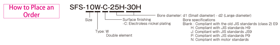
SFS-□W (C) Types
[Specifications]
| Model | Rated torque[N・m] | Misalignment | Max. rotation speed[min-1] | Torsional stiffness[N・m/rad] | Axial stiffness[N/mm] | Moment of inertia[kg・m2] | Mass[kg] | ||
|---|---|---|---|---|---|---|---|---|---|
| Parallel[mm] | Angular[°] | Axial[mm] | |||||||
| SFS-05W-C | 15 | 0.2 | 1(On one side) | ±1.2 | 10000 | 8000 | 21 | 0.14×10⁻³ | 0.40 |
| SFS-06W-C | 30 | 0.3 | 1(On one side) | ±1.6 | 8000 | 14000 | 22 | 0.41×10⁻³ | 0.70 |
| SFS-08W-C | 60 | 0.3 | 1(On one side) | ±2.0 | 6800 | 41000 | 30 | 1.10×10⁻³ | 1.30 |
| SFS-09W-C | 135 | 0.5 | 1(On one side) | ±2.4 | 6000 | 85000 | 61 | 2.20×10⁻³ | 2.10 |
| SFS-10W-C | 190 | 0.5 | 1(On one side) | ±2.8 | 5200 | 125000 | 80 | 3.60×10⁻³ | 2.80 |
| SFS-12W-C | 340 | 0.6 | 1(On one side) | ±3.2 | 4400 | 215000 | 98 | 9.20×10⁻³ | 4.90 |
| SFS-14W-C | 600 | 0.7 | 1(On one side) | ±3.6 | 3800 | 390000 | 156 | 15.00×10⁻³ | 7.10 |
*Max. rotation speed does not take into account dynamic balance.
*The moment of inertia and mass are measured for the maximum bore diameter.
[Dimensions]
| Model | d1・d2 | D | N | L | LF | LP | S | F | d3 | K | M | |
|---|---|---|---|---|---|---|---|---|---|---|---|---|
| Min. | Max. | |||||||||||
| SFS-05W-C | 8 | 20 | 56 | 32 | 58 | 20 | 8 | 5 | 4 | 20 | 24 | 8-M5×15 |
| SFS-06W-C | 8 | 25 | 68 | 40 | 74 | 25 | 12 | 6 | 3 | 24 | 30 | 8-M6×18 |
| SFS-08W-C | 11 | 35 | 82 | 54 | 84 | 30 | 12 | 6 | 2 | 28 | 38 | 8-M6×20 |
| SFS-09W-C | 11 | 38 | 94 | 58 | 98 | 30 | 22 | 8 | 12 | 32 | 42 | 8-M8×27 |
| SFS-10W-C | 16 | 42 | 104 | 68 | 110 | 35 | 20 | 10 | 7 | 34 | 48 | 8-M8×27 |
| SFS-12W-C | 19 | 50 | 126 | 78 | 127 | 40 | 25 | 11 | 10 | 40 | 54 | 8-M10×32 |
| SFS-14W-C | 22 | 60 | 144 | 88 | 144 | 45 | 30 | 12 | 15 | 46 | 61 | 8-M12×38 |
*The nominal diameter of the reamer bolt M is equal to the quantity minus the nominal diameter of the screw threads times the nominal length.
[Standard bore diameter]
| Model | Standard bore diameter d1・d2 [mm] | |||||||||||||||||||||||||||
|---|---|---|---|---|---|---|---|---|---|---|---|---|---|---|---|---|---|---|---|---|---|---|---|---|---|---|---|---|
| 8 | 9 | 10 | 11 | 12 | 14 | 15 | 16 | 17 | 18 | 19 | 20 | 22 | 24 | 25 | 28 | 30 | 32 | 35 | 38 | 40 | 42 | 45 | 48 | 50 | 55 | 56 | 60 | |
| SFS-05W-C | ● | ● | ● | ● | ● | ● | ● | ● | ● | ● | ● | ● | ||||||||||||||||
| SFS-06W-C | ● | ● | ● | ● | ● | ● | ● | ● | ● | ● | ● | ● | ● | ● | ● | |||||||||||||
| SFS-08W-C | ● | ● | ● | ● | ● | ● | ● | ● | ● | ● | ● | ● | ● | ● | ● | ● | ||||||||||||
| SFS-09W-C | ● | ● | ● | ● | ● | ● | ● | ● | ● | ● | ● | ● | ● | ● | ● | ● | ● | |||||||||||
| SFS-10W-C | ● | ● | ● | ● | ● | ● | ● | ● | ● | ● | ● | ● | ● | ● | ● | |||||||||||||
| SFS-12W-C | ● | ● | ● | ● | ● | ● | ● | ● | ● | ● | ● | ● | ● | ● | ● | |||||||||||||
| SFS-14W-C | ● | ● | ● | ● | ● | ● | ● | ● | ● | ● | ● | ● | ● | ● | ● | ● | ||||||||||||
* Bore diameters marked with ● are supported as standard bore diameter. See the standard hole-drilling standards for information.
【Standard Hole-Drilling Standards】
| Models compliant with the old JIS standard (class 2) JIS B 1301 1959 | Models compliant with the new JIS standard (H9) JIS B 1301 1996 | Models compliant with the new JIS standard (JS9) JIS B 1301 1996 | ||||||||||||
|---|---|---|---|---|---|---|---|---|---|---|---|---|---|---|
| Nominal bore diameter | Bore diameter(d1・d2) | Keyway height(W1・W2) | Keyway height(T1・T2) | Set screw hole(M) | Nominal bore diameter | Bore diameter(d1・d2) | Keyway height(W1・W2) | Keyway height(T1・T2) | Set screw hole(M) | Nominal bore diameter | Bore diameter(d1・d2) | Keyway height(W1・W2) | Keyway height(T1・T2) | Set screw hole(M) |
| ToleranceH7,H8 | ToleranceE9 | - | - | ToleranceH7,H8 | ToleranceH9 | - | - | ToleranceH7,H8 | ToleranceJS9 | - | - | |||
| 8 | 8+0.0220 | - | - | 2-M4 | 8H | 8+0.0220 | 3+0.0250 | 9.4+0.30 | 2-M4 | 8J | 8+0.0220 | 3±0.0125 | 9.4+0.30 | 2-M4 |
| 9 | 9+0.0220 | - | - | 2-M4 | 9H | 9+0.0220 | 3+0.0250 | 10.4+0.30 | 2-M4 | 9J | 9+0.0220 | 3±0.0125 | 10.4+0.30 | 2-M4 |
| 10 | 10+0.0220 | - | - | 2-M4 | 10H | 10+0.0220 | 3+0.0250 | 11.4+0.30 | 2-M4 | 10J | 10+0.0220 | 3±0.0125 | 11.4+0.30 | 2-M4 |
| 11 | 11+0.0180 | - | - | 2-M4 | 11H | 11+0.0180 | 4+0.0300 | 12.8+0.30 | 2-M4 | 11J | 11+0.0180 | 4±0.0150 | 12.8+0.30 | 2-M4 |
| 12 | 12+0.0180 | 4+0.050+0.020 | 13.5+0.30 | 2-M4 | 12H | 12+0.0180 | 4+0.0300 | 13.8+0.30 | 2-M4 | 12J | 12+0.0180 | 4±0.0150 | 13.8+0.30 | 2-M4 |
| 14 | 14+0.0180 | 5+0.050+0.020 | 16+0.30 | 2-M4 | 14H | 14+0.0180 | 5+0.0300 | 16.3+0.30 | 2-M4 | 14J | 14+0.0180 | 5±0.0150 | 16.3+0.30 | 2-M4 |
| 15 | 15+0.0180 | 5+0.050+0.020 | 17+0.30 | 2-M4 | 15H | 15+0.0180 | 5+0.0300 | 17.3+0.30 | 2-M4 | 15J | 15+0.0180 | 5±0.0150 | 17.3+0.30 | 2-M4 |
| 16 | 16+0.0180 | 5+0.050+0.020 | 18+0.30 | 2-M4 | 16H | 16+0.0180 | 5+0.0300 | 18.3+0.30 | 2-M4 | 16J | 16+0.0180 | 5±0.0150 | 18.3+0.30 | 2-M4 |
| 17 | 17+0.0180 | 5+0.050+0.020 | 19+0.30 | 2-M4 | 17H | 17+0.0180 | 5+0.0300 | 19.3+0.30 | 2-M4 | 17J | 17+0.0180 | 5±0.0150 | 19.3+0.30 | 2-M4 |
| 18 | 18+0.0180 | 5+0.050+0.020 | 20+0.30 | 2-M4 | 18H | 18+0.0180 | 6+0.0300 | 20.8+0.30 | 2-M5 | 18J | 18+0.0180 | 6±0.0150 | 20.8+0.30 | 2-M5 |
| 19 | 19+0.0210 | 5+0.050+0.020 | 21+0.30 | 2-M4 | 19H | 19+0.0210 | 6+0.0300 | 21.8+0.30 | 2-M5 | 19J | 19+0.0210 | 6±0.0150 | 21.8+0.30 | 2-M5 |
| 20 | 20+0.0210 | 5+0.050+0.020 | 22+0.30 | 2-M4 | 20H | 20+0.0210 | 6+0.0300 | 22.8+0.30 | 2-M5 | 20J | 20+0.0210 | 6±0.0150 | 22.8+0.30 | 2-M5 |
| 22 | 22+0.0210 | 7+0.061+0.025 | 25+0.30 | 2-M6 | 22H | 22+0.0210 | 6+0.0300 | 24.8+0.30 | 2-M5 | 22J | 22+0.0210 | 6±0.0150 | 24.8+0.30 | 2-M5 |
| 24 | 24+0.0210 | 7+0.061+0.025 | 27+0.30 | 2-M6 | 24H | 24+0.0210 | 8+0.0360 | 27.3+0.30 | 2-M6 | 24J | 24+0.0210 | 8±0.0180 | 27.3+0.30 | 2-M6 |
| 25 | 25+0.0210 | 7+0.061+0.025 | 28+0.30 | 2-M6 | 25H | 25+0.0210 | 8+0.0360 | 28.3+0.30 | 2-M6 | 25J | 25+0.0210 | 8±0.0180 | 28.3+0.30 | 2-M6 |
| 28 | 28+0.0210 | 7+0.061+0.025 | 31+0.30 | 2-M6 | 28H | 28+0.0210 | 8+0.0360 | 31.3+0.30 | 2-M6 | 28J | 28+0.0210 | 8±0.0180 | 31.3+0.30 | 2-M6 |
| 30 | 30+0.0210 | 7+0.061+0.025 | 33+0.30 | 2-M6 | 30H | 30+0.0210 | 8+0.0360 | 33.3+0.30 | 2-M6 | 30J | 30+0.0210 | 8±0.0180 | 33.3+0.30 | 2-M6 |
| 32 | 32+0.0250 | 10+0.061+0.025 | 35.5+0.30 | 2-M8 | 32H | 32+0.0250 | 10+0.0360 | 35.3+0.30 | 2-M8 | 32J | 32+0.0250 | 10±0.0180 | 35.3+0.30 | 2-M8 |
| 35 | 35+0.0250 | 10+0.061+0.025 | 38.5+0.30 | 2-M8 | 35H | 35+0.0250 | 10+0.0360 | 38.3+0.30 | 2-M8 | 35J | 35+0.0250 | 10±0.0180 | 38.3+0.30 | 2-M8 |
| 38 | 38+0.0250 | 10+0.061+0.025 | 41.5+0.30 | 2-M8 | 38H | 38+0.0250 | 10+0.0360 | 41.3+0.30 | 2-M8 | 38J | 38+0.0250 | 10±0.0180 | 41.3+0.30 | 2-M8 |
| 40 | 40+0.0250 | 10+0.061+0.025 | 43.5+0.30 | 2-M8 | 40H | 40+0.0250 | 12+0.0430 | 43.3+0.30 | 2-M8 | 40J | 40+0.0250 | 12±0.0215 | 43.3+0.30 | 2-M8 |
| 42 | 42+0.0250 | 12+0.075+0.032 | 45.5+0.30 | 2-M8 | 42H | 42+0.0250 | 12+0.0430 | 45.3+0.30 | 2-M8 | 42J | 42+0.0250 | 12±0.0215 | 45.3+0.30 | 2-M8 |
| 45 | 45+0.0250 | 12+0.075+0.032 | 48.5+0.30 | 2-M8 | 45H | 45+0.0250 | 14+0.0430 | 48.8+0.30 | 2-M10 | 45J | 45+0.0250 | 14±0.0215 | 48.8+0.30 | 2-M10 |
| 48 | 48+0.0250 | 12+0.075+0.032 | 51.5+0.30 | 2-M8 | 48H | 48+0.0250 | 14+0.0430 | 51.8+0.30 | 2-M10 | 48J | 48+0.0250 | 14±0.0215 | 51.8+0.30 | 2-M10 |
| 50 | 50+0.0250 | 12+0.075+0.032 | 53.5+0.30 | 2-M8 | 50H | 50+0.0250 | 14+0.0430 | 53.8+0.30 | 2-M10 | 50J | 50+0.0250 | 14±0.0215 | 53.8+0.30 | 2-M10 |
| 55 | 55+0.0300 | 15+0.075+0.032 | 60+0.30 | 2-M10 | 55H | 55+0.0300 | 16+0.0430 | 59.3+0.30 | 2-M10 | 55J | 55+0.0300 | 16±0.0215 | 59.3+0.30 | 2-M10 |
| 56 | 56+0.0300 | 15+0.075+0.032 | 61+0.30 | 2-M10 | 56H | 56+0.0300 | 16+0.0430 | 60.3+0.30 | 2-M10 | 56J | 56+0.0300 | 16±0.0215 | 60.3+0.30 | 2-M10 |
| 60 | 60+0.0300 | 15+0.075+0.032 | 65+0.30 | 2-M10 | 60H | 60+0.0300 | 18+0.0430 | 64.4+0.30 | 2-M10 | 60J | 60+0.0300 | 18±0.0215 | 64.4+0.30 | 2-M10 |
| Models compliant with the new JIS standard (P9) JIS B 1301 1996 | Models compliant with the motor standard JIS C 4210 2001 | ||||||||
|---|---|---|---|---|---|---|---|---|---|
| Nominal bore diameter | Bore diameter(d1・d2) | Keyway width(W1・W2) | Keyway height(T1・T2) | Set screw hole(M) | Nominal bore diameter | Bore diameter(d1・d2) | Keyway width(W1・W2) | Keyway height(T1・T2) | Set screw hole(M) |
| ToleranceH7,H8 | ToleranceP9 | + 0.30 0 | - | - | ToleranceG7,F7 | ToleranceH9 | - | ||
| 8P | 8 +0.022 | 3-0.006-0.031 | 9.4+0.30 | 2-M4 | - | - | - | - | - |
| 9P | 9 +0.022 | 3-0.006-0.031 | 10.4+0.30 | 2-M4 | - | - | - | - | - |
| 10P | 10 +0.022 | 3-0.006-0.031 | 11.4+0.30 | 2-M4 | - | - | - | - | - |
| 11P | 11+0.018 | 4-0.042-0.012 | 12.8+0.30 | 2-M4 | - | - | - | - | - |
| 12P | 12 +0.018 | 4-0.042-0.012 | 13.8+0.30 | 2-M4 | - | - | - | - | - |
| 14P | 14+0.018 | 5-0.042-0.012 | 16.3+0.30 | 2-M4 | 14N | 14+0.024+0.006 | 5+0.030 | 16.3+0.30 | 2-M4 |
| 15P | 15+0.018 | 5-0.042-0.012 | 17.3+0.30 | 2-M4 | - | - | - | - | - |
| 16P | 16+0.018 | 5-0.042-0.012 | 18.3+0.30 | 2-M4 | - | - | - | - | - |
| 17P | 17+0.018 | 5-0.042-0.012 | 19.3+0.30 | 2-M4 | - | - | - | - | - |
| 18P | 18+0.018 | 6-0.042-0.012 | 20.8+0.30 | 2-M5 | - | - | - | - | - |
| 19P | 19 +0.021 | 6-0.042-0.012 | 21.8+0.30 | 2-M5 | 19N | 19+0.028+0.007 | 6+0.030 | 21.8+0.30 | 2-M5 |
| 20P | 20 +0.021 | 6-0.042-0.012 | 22.8+0.30 | 2-M5 | - | - | - | - | - |
| 22P | 22 +0.021 | 6-0.042-0.012 | 24.8+0.30 | 2-M5 | - | - | - | - | - |
| 24P | 24 +0.021 | 8-0.051-0.015 | 27.3+0.30 | 2-M6 | 24N | 24+0.028+0.007 | 8+0.036 | 27.3+0.30 | 2-M6 |
| 25P | 25 +0.021 | 8-0.051-0.015 | 28.3+0.30 | 2-M6 | - | - | - | - | - |
| 28P | 28 +0.021 | 8-0.051-0.015 | 31.3+0.30 | 2-M6 | 28N | 28+0.028+0.007 | 8+0.036 | 31.3+0.30 | 2-M6 |
| 30P | 30 +0.021 | 8-0.051-0.015 | 33.3+0.30 | 2-M6 | - | - | - | - | - |
| 32P | 32 +0.025 | 10-0.051-0.015 | 35.3+0.30 | 2-M8 | - | - | - | ||
| 35P | 35 +0.025 | 10-0.051-0.015 | 38.3+0.30 | 2-M8 | - | - | - | - | |
| 38P | 38 +0.025 | 10-0.051-0.015 | 41.3+0.30 | 2-M8 | 38N | 38+0.050+0.025 | 10+0.036 | 41.3+0.30 | 2-M8 |
| 40P | 40 +0.025 | 12-0.061-0.018 | 43.3+0.30 | 2-M8 | - | - | - | - | - |
| 42P | 42 +0.025 | 12-0.061-0.018 | 45.3+0.30 | 2-M8 | 42N | 42+0.050+0.025 | 12+0.043 | 45.3+0.30 | 2-M8 |
| 45P | 45 +0.025 | 14-0.061-0.018 | 48.8+0.30 | 2-M10 | - | - | - | - | - |
| 48P | 48 +0.025 | 14-0.061-0.018 | 51.8+0.30 | 2-M10 | 48N | 48+0.050+0.025 | 14+0.043 | 51.8+0.30 | 2-M10 |
| 50P | 50 +0.025 | 14-0.061-0.018 | 53.8+0.30 | 2-M10 | - | - | - | - | - |
| 55P | 55 +0.030 | 16-0.061-0.018 | 59.3+0.30 | 2-M10 | 55N | 55+0.060+0.030 | 16+0.043 | 59.3+0.30 | 2-M10 |
| 56P | 56 +0.030 | 16-0.061-0.018 | 60.3+0.30 | 2-M10 | - | - | - | - | - |
| 60P | 60 +0.030 | 18-0.061-0.018 | 64.4+0.30 | 2-M10 | 60N | 60+0.060+0.030 | 18+0.043 | 64.4+0.30 | 2-M10 |
※Positions of set screws and keyways are not on the same plane.
※Set screws are included with the product.
※Positioning precision for keyway milling is determined by sight.
※Contact Miki Pulley when the keyway requires a positioning precision for a particular flange hub.
※Consult the technical documentation at the end of this volume for standard dimensions for bore drilling other than those given here.
【Set screw position】
| Model | Distance from edge [mm] |
|---|---|
| SFS-05 | 7 |
| SFS-06 | 9 |
| SFS-08 | 10 |
| SFS-09 | 10 |
| SFS-10 | 12 |
| SFS-12 | 12 |
| SFS-14 | 15 |
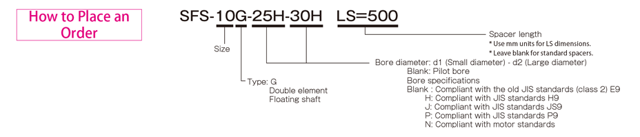
SFS-□G Types
[Specifications]
| Model | Rated torque[N・m] | Misalignment | Max. rotation speed[min-1] | Torsional stiffness[N・m/rad] | Axial stiffness[N/mm] | Moment of inertia[kg・m2] | Mass[kg] | ||
|---|---|---|---|---|---|---|---|---|---|
| Parallel[mm] | Angular[°] | Axial[mm] | |||||||
| SFS-05G | 20 | 0.5 | 1(On one side) | ±1.2 | 20000 | 8000 | 21 | 0.20×10⁻³ | 0.50 |
| SFS-06G | 40 | 0.5 | 1(On one side) | ±1.6 | 16000 | 14000 | 22 | 0.55×10⁻³ | 0.90 |
| SFS-08G | 80 | 0.5 | 1(On one side) | ±2.0 | 13000 | 41000 | 30 | 1.50×10⁻³ | 1.70 |
| SFS-09G | 180 | 0.6 | 1(On one side) | ±2.4 | 12000 | 85000 | 61 | 2.90×10⁻³ | 2.40 |
| SFS-10G | 250 | 0.6 | 1(On one side) | ±2.8 | 10000 | 125000 | 80 | 4.60×10⁻³ | 3.30 |
| SFS-12G | 450 | 0.8 | 1(On one side) | ±3.2 | 8000 | 215000 | 98 | 11.80×10⁻³ | 5.80 |
| SFS-14G | 800 | 0.9 | 1(On one side) | ±3.6 | 7000 | 390000 | 156 | 21.20×10⁻³ | 8.60 |
*Max. rotation speed does not take into account dynamic balance.
*The moment of inertia and mass are measured for the maximum bore diameter.
[Dimensions]

| Model | d1・d2 | D | N | L | LF | LS | S | F | K | M | ||
|---|---|---|---|---|---|---|---|---|---|---|---|---|
| Pilot bore | Min. | Max. | ||||||||||
| SFS-05G | 7 | 8 | 20 | 56 | 32 | 74 | 20 | 24 | 5 | 11 | 24 | 8-M5×22 |
| SFS-06G | 7 | 8 | 25 | 68 | 40 | 86 | 25 | 24 | 6 | 10 | 30 | 8-M6×25 |
| SFS-08G | 10 | 11 | 35 | 82 | 54 | 98 | 30 | 26 | 6 | 11 | 38 | 8-M6×29 |
| SFS-09G | 10 | 11 | 38 | 94 | 58 | 106 | 30 | 30 | 8 | 21 | 42 | 8-M8×36 |
| SFS-10G | 15 | 16 | 42 | 104 | 68 | 120 | 35 | 30 | 10 | 16 | 48 | 8-M8×36 |
| SFS-12G | 18 | 19 | 50 | 126 | 78 | 140 | 40 | 38 | 11 | 23 | 54 | 8-M10×45 |
| SFS-14G | 20 | 22 | 60 | 144 | 88 | 160 | 45 | 46 | 12 | 31 | 61 | 8-M12×54 |
*Pilot bores are to be drilled into the part.
*If you require a product with an LS dimension that exceeds those above, contact Miki Pulley with your required dimension [mm]. Please contact Miki Pulley for assistance if the LS dimension is less than those
*The nominal diameter of the reamer bolt M is equal to the quantity minus the nominal diameter of the screw threads times the nominal length.
[Standard bore diameter]
| Model | Standard bore diameter d1・d2 [mm] | |||||||||||||||||||||||||||
|---|---|---|---|---|---|---|---|---|---|---|---|---|---|---|---|---|---|---|---|---|---|---|---|---|---|---|---|---|
| 8 | 9 | 10 | 11 | 12 | 14 | 15 | 16 | 17 | 18 | 19 | 20 | 22 | 24 | 25 | 28 | 30 | 32 | 35 | 38 | 40 | 42 | 45 | 48 | 50 | 55 | 56 | 60 | |
| SFS-05G | ● | ● | ● | ● | ● | ● | ● | ● | ● | ● | ● | ● | ||||||||||||||||
| SFS-06G | ● | ● | ● | ● | ● | ● | ● | ● | ● | ● | ● | ● | ● | ● | ● | |||||||||||||
| SFS-08G | ● | ● | ● | ● | ● | ● | ● | ● | ● | ● | ● | ● | ● | ● | ● | ● | ||||||||||||
| SFS-09G | ● | ● | ● | ● | ● | ● | ● | ● | ● | ● | ● | ● | ● | ● | ● | ● | ● | |||||||||||
| SFS-10G | ● | ● | ● | ● | ● | ● | ● | ● | ● | ● | ● | ● | ● | ● | ● | |||||||||||||
| SFS-12G | ● | ● | ● | ● | ● | ● | ● | ● | ● | ● | ● | ● | ● | ● | ● | |||||||||||||
| SFS-14G | ● | ● | ● | ● | ● | ● | ● | ● | ● | ● | ● | ● | ● | ● | ● | ● | ||||||||||||
* Bore diameters marked with ● are supported as standard bore diameter. See the standard hole-drilling standards for information.
【Standard Hole-Drilling Standards】
| Models compliant with the old JIS standard (class 2) JIS B 1301 1959 | Models compliant with the new JIS standard (H9) JIS B 1301 1996 | Models compliant with the new JIS standard (JS9) JIS B 1301 1996 | ||||||||||||
|---|---|---|---|---|---|---|---|---|---|---|---|---|---|---|
| Nominal bore diameter | Bore diameter(d1・d2) | Keyway height(W1・W2) | Keyway height(T1・T2) | Set screw hole(M) | Nominal bore diameter | Bore diameter(d1・d2) | Keyway height(W1・W2) | Keyway height(T1・T2) | Set screw hole(M) | Nominal bore diameter | Bore diameter(d1・d2) | Keyway height(W1・W2) | Keyway height(T1・T2) | Set screw hole(M) |
| ToleranceH7,H8 | ToleranceE9 | - | - | ToleranceH7,H8 | ToleranceH9 | - | - | ToleranceH7,H8 | ToleranceJS9 | - | - | |||
| 8 | 8+0.0220 | - | - | 2-M4 | 8H | 8+0.0220 | 3+0.0250 | 9.4+0.30 | 2-M4 | 8J | 8+0.0220 | 3±0.0125 | 9.4+0.30 | 2-M4 |
| 9 | 9+0.0220 | - | - | 2-M4 | 9H | 9+0.0220 | 3+0.0250 | 10.4+0.30 | 2-M4 | 9J | 9+0.0220 | 3±0.0125 | 10.4+0.30 | 2-M4 |
| 10 | 10+0.0220 | - | - | 2-M4 | 10H | 10+0.0220 | 3+0.0250 | 11.4+0.30 | 2-M4 | 10J | 10+0.0220 | 3±0.0125 | 11.4+0.30 | 2-M4 |
| 11 | 11+0.0180 | - | - | 2-M4 | 11H | 11+0.0180 | 4+0.0300 | 12.8+0.30 | 2-M4 | 11J | 11+0.0180 | 4±0.0150 | 12.8+0.30 | 2-M4 |
| 12 | 12+0.0180 | 4+0.050+0.020 | 13.5+0.30 | 2-M4 | 12H | 12+0.0180 | 4+0.0300 | 13.8+0.30 | 2-M4 | 12J | 12+0.0180 | 4±0.0150 | 13.8+0.30 | 2-M4 |
| 14 | 14+0.0180 | 5+0.050+0.020 | 16+0.30 | 2-M4 | 14H | 14+0.0180 | 5+0.0300 | 16.3+0.30 | 2-M4 | 14J | 14+0.0180 | 5±0.0150 | 16.3+0.30 | 2-M4 |
| 15 | 15+0.0180 | 5+0.050+0.020 | 17+0.30 | 2-M4 | 15H | 15+0.0180 | 5+0.0300 | 17.3+0.30 | 2-M4 | 15J | 15+0.0180 | 5±0.0150 | 17.3+0.30 | 2-M4 |
| 16 | 16+0.0180 | 5+0.050+0.020 | 18+0.30 | 2-M4 | 16H | 16+0.0180 | 5+0.0300 | 18.3+0.30 | 2-M4 | 16J | 16+0.0180 | 5±0.0150 | 18.3+0.30 | 2-M4 |
| 17 | 17+0.0180 | 5+0.050+0.020 | 19+0.30 | 2-M4 | 17H | 17+0.0180 | 5+0.0300 | 19.3+0.30 | 2-M4 | 17J | 17+0.0180 | 5±0.0150 | 19.3+0.30 | 2-M4 |
| 18 | 18+0.0180 | 5+0.050+0.020 | 20+0.30 | 2-M4 | 18H | 18+0.0180 | 6+0.0300 | 20.8+0.30 | 2-M5 | 18J | 18+0.0180 | 6±0.0150 | 20.8+0.30 | 2-M5 |
| 19 | 19+0.0210 | 5+0.050+0.020 | 21+0.30 | 2-M4 | 19H | 19+0.0210 | 6+0.0300 | 21.8+0.30 | 2-M5 | 19J | 19+0.0210 | 6±0.0150 | 21.8+0.30 | 2-M5 |
| 20 | 20+0.0210 | 5+0.050+0.020 | 22+0.30 | 2-M4 | 20H | 20+0.0210 | 6+0.0300 | 22.8+0.30 | 2-M5 | 20J | 20+0.0210 | 6±0.0150 | 22.8+0.30 | 2-M5 |
| 22 | 22+0.0210 | 7+0.061+0.025 | 25+0.30 | 2-M6 | 22H | 22+0.0210 | 6+0.0300 | 24.8+0.30 | 2-M5 | 22J | 22+0.0210 | 6±0.0150 | 24.8+0.30 | 2-M5 |
| 24 | 24+0.0210 | 7+0.061+0.025 | 27+0.30 | 2-M6 | 24H | 24+0.0210 | 8+0.0360 | 27.3+0.30 | 2-M6 | 24J | 24+0.0210 | 8±0.0180 | 27.3+0.30 | 2-M6 |
| 25 | 25+0.0210 | 7+0.061+0.025 | 28+0.30 | 2-M6 | 25H | 25+0.0210 | 8+0.0360 | 28.3+0.30 | 2-M6 | 25J | 25+0.0210 | 8±0.0180 | 28.3+0.30 | 2-M6 |
| 28 | 28+0.0210 | 7+0.061+0.025 | 31+0.30 | 2-M6 | 28H | 28+0.0210 | 8+0.0360 | 31.3+0.30 | 2-M6 | 28J | 28+0.0210 | 8±0.0180 | 31.3+0.30 | 2-M6 |
| 30 | 30+0.0210 | 7+0.061+0.025 | 33+0.30 | 2-M6 | 30H | 30+0.0210 | 8+0.0360 | 33.3+0.30 | 2-M6 | 30J | 30+0.0210 | 8±0.0180 | 33.3+0.30 | 2-M6 |
| 32 | 32+0.0250 | 10+0.061+0.025 | 35.5+0.30 | 2-M8 | 32H | 32+0.0250 | 10+0.0360 | 35.3+0.30 | 2-M8 | 32J | 32+0.0250 | 10±0.0180 | 35.3+0.30 | 2-M8 |
| 35 | 35+0.0250 | 10+0.061+0.025 | 38.5+0.30 | 2-M8 | 35H | 35+0.0250 | 10+0.0360 | 38.3+0.30 | 2-M8 | 35J | 35+0.0250 | 10±0.0180 | 38.3+0.30 | 2-M8 |
| 38 | 38+0.0250 | 10+0.061+0.025 | 41.5+0.30 | 2-M8 | 38H | 38+0.0250 | 10+0.0360 | 41.3+0.30 | 2-M8 | 38J | 38+0.0250 | 10±0.0180 | 41.3+0.30 | 2-M8 |
| 40 | 40+0.0250 | 10+0.061+0.025 | 43.5+0.30 | 2-M8 | 40H | 40+0.0250 | 12+0.0430 | 43.3+0.30 | 2-M8 | 40J | 40+0.0250 | 12±0.0215 | 43.3+0.30 | 2-M8 |
| 42 | 42+0.0250 | 12+0.075+0.032 | 45.5+0.30 | 2-M8 | 42H | 42+0.0250 | 12+0.0430 | 45.3+0.30 | 2-M8 | 42J | 42+0.0250 | 12±0.0215 | 45.3+0.30 | 2-M8 |
| 45 | 45+0.0250 | 12+0.075+0.032 | 48.5+0.30 | 2-M8 | 45H | 45+0.0250 | 14+0.0430 | 48.8+0.30 | 2-M10 | 45J | 45+0.0250 | 14±0.0215 | 48.8+0.30 | 2-M10 |
| 48 | 48+0.0250 | 12+0.075+0.032 | 51.5+0.30 | 2-M8 | 48H | 48+0.0250 | 14+0.0430 | 51.8+0.30 | 2-M10 | 48J | 48+0.0250 | 14±0.0215 | 51.8+0.30 | 2-M10 |
| 50 | 50+0.0250 | 12+0.075+0.032 | 53.5+0.30 | 2-M8 | 50H | 50+0.0250 | 14+0.0430 | 53.8+0.30 | 2-M10 | 50J | 50+0.0250 | 14±0.0215 | 53.8+0.30 | 2-M10 |
| 55 | 55+0.0300 | 15+0.075+0.032 | 60+0.30 | 2-M10 | 55H | 55+0.0300 | 16+0.0430 | 59.3+0.30 | 2-M10 | 55J | 55+0.0300 | 16±0.0215 | 59.3+0.30 | 2-M10 |
| 56 | 56+0.0300 | 15+0.075+0.032 | 61+0.30 | 2-M10 | 56H | 56+0.0300 | 16+0.0430 | 60.3+0.30 | 2-M10 | 56J | 56+0.0300 | 16±0.0215 | 60.3+0.30 | 2-M10 |
| 60 | 60+0.0300 | 15+0.075+0.032 | 65+0.30 | 2-M10 | 60H | 60+0.0300 | 18+0.0430 | 64.4+0.30 | 2-M10 | 60J | 60+0.0300 | 18±0.0215 | 64.4+0.30 | 2-M10 |
| Models compliant with the new JIS standard (P9) JIS B 1301 1996 | Models compliant with the motor standard JIS C 4210 2001 | ||||||||
|---|---|---|---|---|---|---|---|---|---|
| Nominal bore diameter | Bore diameter(d1・d2) | Keyway width(W1・W2) | Keyway height(T1・T2) | Set screw hole(M) | Nominal bore diameter | Bore diameter(d1・d2) | Keyway width(W1・W2) | Keyway height(T1・T2) | Set screw hole(M) |
| ToleranceH7,H8 | ToleranceP9 | + 0.30 0 | - | - | ToleranceG7,F7 | ToleranceH9 | - | ||
| 8P | 8 +0.022 | 3-0.006-0.031 | 9.4+0.30 | 2-M4 | - | - | - | - | - |
| 9P | 9 +0.022 | 3-0.006-0.031 | 10.4+0.30 | 2-M4 | - | - | - | - | - |
| 10P | 10 +0.022 | 3-0.006-0.031 | 11.4+0.30 | 2-M4 | - | - | - | - | - |
| 11P | 11+0.018 | 4-0.042-0.012 | 12.8+0.30 | 2-M4 | - | - | - | - | - |
| 12P | 12 +0.018 | 4-0.042-0.012 | 13.8+0.30 | 2-M4 | - | - | - | - | - |
| 14P | 14+0.018 | 5-0.042-0.012 | 16.3+0.30 | 2-M4 | 14N | 14+0.024+0.006 | 5+0.030 | 16.3+0.30 | 2-M4 |
| 15P | 15+0.018 | 5-0.042-0.012 | 17.3+0.30 | 2-M4 | - | - | - | - | - |
| 16P | 16+0.018 | 5-0.042-0.012 | 18.3+0.30 | 2-M4 | - | - | - | - | - |
| 17P | 17+0.018 | 5-0.042-0.012 | 19.3+0.30 | 2-M4 | - | - | - | - | - |
| 18P | 18+0.018 | 6-0.042-0.012 | 20.8+0.30 | 2-M5 | - | - | - | - | - |
| 19P | 19 +0.021 | 6-0.042-0.012 | 21.8+0.30 | 2-M5 | 19N | 19+0.028+0.007 | 6+0.030 | 21.8+0.30 | 2-M5 |
| 20P | 20 +0.021 | 6-0.042-0.012 | 22.8+0.30 | 2-M5 | - | - | - | - | - |
| 22P | 22 +0.021 | 6-0.042-0.012 | 24.8+0.30 | 2-M5 | - | - | - | - | - |
| 24P | 24 +0.021 | 8-0.051-0.015 | 27.3+0.30 | 2-M6 | 24N | 24+0.028+0.007 | 8+0.036 | 27.3+0.30 | 2-M6 |
| 25P | 25 +0.021 | 8-0.051-0.015 | 28.3+0.30 | 2-M6 | - | - | - | - | - |
| 28P | 28 +0.021 | 8-0.051-0.015 | 31.3+0.30 | 2-M6 | 28N | 28+0.028+0.007 | 8+0.036 | 31.3+0.30 | 2-M6 |
| 30P | 30 +0.021 | 8-0.051-0.015 | 33.3+0.30 | 2-M6 | - | - | - | - | - |
| 32P | 32 +0.025 | 10-0.051-0.015 | 35.3+0.30 | 2-M8 | - | - | - | ||
| 35P | 35 +0.025 | 10-0.051-0.015 | 38.3+0.30 | 2-M8 | - | - | - | - | |
| 38P | 38 +0.025 | 10-0.051-0.015 | 41.3+0.30 | 2-M8 | 38N | 38+0.050+0.025 | 10+0.036 | 41.3+0.30 | 2-M8 |
| 40P | 40 +0.025 | 12-0.061-0.018 | 43.3+0.30 | 2-M8 | - | - | - | - | - |
| 42P | 42 +0.025 | 12-0.061-0.018 | 45.3+0.30 | 2-M8 | 42N | 42+0.050+0.025 | 12+0.043 | 45.3+0.30 | 2-M8 |
| 45P | 45 +0.025 | 14-0.061-0.018 | 48.8+0.30 | 2-M10 | - | - | - | - | - |
| 48P | 48 +0.025 | 14-0.061-0.018 | 51.8+0.30 | 2-M10 | 48N | 48+0.050+0.025 | 14+0.043 | 51.8+0.30 | 2-M10 |
| 50P | 50 +0.025 | 14-0.061-0.018 | 53.8+0.30 | 2-M10 | - | - | - | - | - |
| 55P | 55 +0.030 | 16-0.061-0.018 | 59.3+0.30 | 2-M10 | 55N | 55+0.060+0.030 | 16+0.043 | 59.3+0.30 | 2-M10 |
| 56P | 56 +0.030 | 16-0.061-0.018 | 60.3+0.30 | 2-M10 | - | - | - | - | - |
| 60P | 60 +0.030 | 18-0.061-0.018 | 64.4+0.30 | 2-M10 | 60N | 60+0.060+0.030 | 18+0.043 | 64.4+0.30 | 2-M10 |
※Positions of set screws and keyways are not on the same plane.
※Set screws are included with the product.
※Positioning precision for keyway milling is determined by sight.
※Contact Miki Pulley when the keyway requires a positioning precision for a particular flange hub.
※Consult the technical documentation at the end of this volume for standard dimensions for bore drilling other than those given here.
【Set screw position】
| Model | Distance from edge [mm] |
|---|---|
| SFS-05 | 7 |
| SFS-06 | 9 |
| SFS-08 | 10 |
| SFS-09 | 10 |
| SFS-10 | 12 |
| SFS-12 | 12 |
| SFS-14 | 15 |
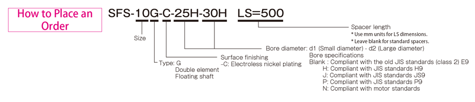
SFS-□G (C) Types
[Specifications]
[Dimensions]
| Model | d1・d2 | D | N | L | LF | LS | S | F | K | M | ||
|---|---|---|---|---|---|---|---|---|---|---|---|---|
| Pilot bore | Min. | Max. | ||||||||||
| SFS-05G-C | 7 | 8 | 20 | 56 | 32 | 74 | 20 | 24 | 5 | 11 | 24 | 8-M5×22 |
| SFS-06G-C | 7 | 8 | 25 | 68 | 40 | 86 | 25 | 24 | 6 | 10 | 30 | 8-M6×25 |
| SFS-08G-C | 10 | 11 | 35 | 82 | 54 | 98 | 30 | 26 | 6 | 11 | 38 | 8-M6×29 |
| SFS-09G-C | 10 | 11 | 38 | 94 | 58 | 106 | 30 | 30 | 8 | 21 | 42 | 8-M8×36 |
| SFS-10G-C | 15 | 16 | 42 | 104 | 68 | 120 | 35 | 30 | 10 | 16 | 48 | 8-M8×36 |
| SFS-12G-C | 18 | 19 | 50 | 126 | 78 | 140 | 40 | 38 | 11 | 23 | 54 | 8-M10×45 |
| SFS-14G-C | 20 | 22 | 60 | 144 | 88 | 160 | 45 | 46 | 12 | 31 | 61 | 8-M12×54 |
* If you require a product with an LS dimension that exceeds those above, contact Miki Pulley with your required dimension [mm]. Please contact Miki Pulley for assistance if the LS dimension is less than thoseabove or if LS ≧ 1000.
* Please note that when the LS dimension exceeds 100 mm with the electroless nickel plating specification (SFS- □ G-C), the insertion length of the shaft cannot exceed the LS dimension.
* The nominal diameter of the reamer bolt M is equal to the quantity minus the nominal diameter of the screw threads times the nominal length.
[Standard bore diameter]
| Model | Standard bore diameter d1・d2 [mm] | |||||||||||||||||||||||||||
|---|---|---|---|---|---|---|---|---|---|---|---|---|---|---|---|---|---|---|---|---|---|---|---|---|---|---|---|---|
| 8 | 9 | 10 | 11 | 12 | 14 | 15 | 16 | 17 | 18 | 19 | 20 | 22 | 24 | 25 | 28 | 30 | 32 | 35 | 38 | 40 | 42 | 45 | 48 | 50 | 55 | 56 | 60 | |
| SFS-05G-C | ● | ● | ● | ● | ● | ● | ● | ● | ● | ● | ● | ● | ||||||||||||||||
| SFS-06G-C | ● | ● | ● | ● | ● | ● | ● | ● | ● | ● | ● | ● | ● | ● | ● | |||||||||||||
| SFS-08G-C | ● | ● | ● | ● | ● | ● | ● | ● | ● | ● | ● | ● | ● | ● | ● | ● | ||||||||||||
| SFS-09G-C | ● | ● | ● | ● | ● | ● | ● | ● | ● | ● | ● | ● | ● | ● | ● | ● | ● | |||||||||||
| SFS-10G-C | ● | ● | ● | ● | ● | ● | ● | ● | ● | ● | ● | ● | ● | ● | ● | |||||||||||||
| SFS-12G-C | ● | ● | ● | ● | ● | ● | ● | ● | ● | ● | ● | ● | ● | ● | ● | |||||||||||||
| SFS-14G-C | ● | ● | ● | ● | ● | ● | ● | ● | ● | ● | ● | ● | ● | ● | ● | ● | ||||||||||||
* Bore diameters marked with ● are supported as standard bore diameter. See the standard hole-drilling standards for information
【Standard Hole-Drilling Standards】
| Models compliant with the old JIS standard (class 2) JIS B 1301 1959 | Models compliant with the new JIS standard (H9) JIS B 1301 1996 | Models compliant with the new JIS standard (JS9) JIS B 1301 1996 | ||||||||||||
|---|---|---|---|---|---|---|---|---|---|---|---|---|---|---|
| Nominal bore diameter | Bore diameter(d1・d2) | Keyway height(W1・W2) | Keyway height(T1・T2) | Set screw hole(M) | Nominal bore diameter | Bore diameter(d1・d2) | Keyway height(W1・W2) | Keyway height(T1・T2) | Set screw hole(M) | Nominal bore diameter | Bore diameter(d1・d2) | Keyway height(W1・W2) | Keyway height(T1・T2) | Set screw hole(M) |
| ToleranceH7,H8 | ToleranceE9 | - | - | ToleranceH7,H8 | ToleranceH9 | - | - | ToleranceH7,H8 | ToleranceJS9 | - | - | |||
| 8 | 8+0.0220 | - | - | 2-M4 | 8H | 8+0.0220 | 3+0.0250 | 9.4+0.30 | 2-M4 | 8J | 8+0.0220 | 3±0.0125 | 9.4+0.30 | 2-M4 |
| 9 | 9+0.0220 | - | - | 2-M4 | 9H | 9+0.0220 | 3+0.0250 | 10.4+0.30 | 2-M4 | 9J | 9+0.0220 | 3±0.0125 | 10.4+0.30 | 2-M4 |
| 10 | 10+0.0220 | - | - | 2-M4 | 10H | 10+0.0220 | 3+0.0250 | 11.4+0.30 | 2-M4 | 10J | 10+0.0220 | 3±0.0125 | 11.4+0.30 | 2-M4 |
| 11 | 11+0.0180 | - | - | 2-M4 | 11H | 11+0.0180 | 4+0.0300 | 12.8+0.30 | 2-M4 | 11J | 11+0.0180 | 4±0.0150 | 12.8+0.30 | 2-M4 |
| 12 | 12+0.0180 | 4+0.050+0.020 | 13.5+0.30 | 2-M4 | 12H | 12+0.0180 | 4+0.0300 | 13.8+0.30 | 2-M4 | 12J | 12+0.0180 | 4±0.0150 | 13.8+0.30 | 2-M4 |
| 14 | 14+0.0180 | 5+0.050+0.020 | 16+0.30 | 2-M4 | 14H | 14+0.0180 | 5+0.0300 | 16.3+0.30 | 2-M4 | 14J | 14+0.0180 | 5±0.0150 | 16.3+0.30 | 2-M4 |
| 15 | 15+0.0180 | 5+0.050+0.020 | 17+0.30 | 2-M4 | 15H | 15+0.0180 | 5+0.0300 | 17.3+0.30 | 2-M4 | 15J | 15+0.0180 | 5±0.0150 | 17.3+0.30 | 2-M4 |
| 16 | 16+0.0180 | 5+0.050+0.020 | 18+0.30 | 2-M4 | 16H | 16+0.0180 | 5+0.0300 | 18.3+0.30 | 2-M4 | 16J | 16+0.0180 | 5±0.0150 | 18.3+0.30 | 2-M4 |
| 17 | 17+0.0180 | 5+0.050+0.020 | 19+0.30 | 2-M4 | 17H | 17+0.0180 | 5+0.0300 | 19.3+0.30 | 2-M4 | 17J | 17+0.0180 | 5±0.0150 | 19.3+0.30 | 2-M4 |
| 18 | 18+0.0180 | 5+0.050+0.020 | 20+0.30 | 2-M4 | 18H | 18+0.0180 | 6+0.0300 | 20.8+0.30 | 2-M5 | 18J | 18+0.0180 | 6±0.0150 | 20.8+0.30 | 2-M5 |
| 19 | 19+0.0210 | 5+0.050+0.020 | 21+0.30 | 2-M4 | 19H | 19+0.0210 | 6+0.0300 | 21.8+0.30 | 2-M5 | 19J | 19+0.0210 | 6±0.0150 | 21.8+0.30 | 2-M5 |
| 20 | 20+0.0210 | 5+0.050+0.020 | 22+0.30 | 2-M4 | 20H | 20+0.0210 | 6+0.0300 | 22.8+0.30 | 2-M5 | 20J | 20+0.0210 | 6±0.0150 | 22.8+0.30 | 2-M5 |
| 22 | 22+0.0210 | 7+0.061+0.025 | 25+0.30 | 2-M6 | 22H | 22+0.0210 | 6+0.0300 | 24.8+0.30 | 2-M5 | 22J | 22+0.0210 | 6±0.0150 | 24.8+0.30 | 2-M5 |
| 24 | 24+0.0210 | 7+0.061+0.025 | 27+0.30 | 2-M6 | 24H | 24+0.0210 | 8+0.0360 | 27.3+0.30 | 2-M6 | 24J | 24+0.0210 | 8±0.0180 | 27.3+0.30 | 2-M6 |
| 25 | 25+0.0210 | 7+0.061+0.025 | 28+0.30 | 2-M6 | 25H | 25+0.0210 | 8+0.0360 | 28.3+0.30 | 2-M6 | 25J | 25+0.0210 | 8±0.0180 | 28.3+0.30 | 2-M6 |
| 28 | 28+0.0210 | 7+0.061+0.025 | 31+0.30 | 2-M6 | 28H | 28+0.0210 | 8+0.0360 | 31.3+0.30 | 2-M6 | 28J | 28+0.0210 | 8±0.0180 | 31.3+0.30 | 2-M6 |
| 30 | 30+0.0210 | 7+0.061+0.025 | 33+0.30 | 2-M6 | 30H | 30+0.0210 | 8+0.0360 | 33.3+0.30 | 2-M6 | 30J | 30+0.0210 | 8±0.0180 | 33.3+0.30 | 2-M6 |
| 32 | 32+0.0250 | 10+0.061+0.025 | 35.5+0.30 | 2-M8 | 32H | 32+0.0250 | 10+0.0360 | 35.3+0.30 | 2-M8 | 32J | 32+0.0250 | 10±0.0180 | 35.3+0.30 | 2-M8 |
| 35 | 35+0.0250 | 10+0.061+0.025 | 38.5+0.30 | 2-M8 | 35H | 35+0.0250 | 10+0.0360 | 38.3+0.30 | 2-M8 | 35J | 35+0.0250 | 10±0.0180 | 38.3+0.30 | 2-M8 |
| 38 | 38+0.0250 | 10+0.061+0.025 | 41.5+0.30 | 2-M8 | 38H | 38+0.0250 | 10+0.0360 | 41.3+0.30 | 2-M8 | 38J | 38+0.0250 | 10±0.0180 | 41.3+0.30 | 2-M8 |
| 40 | 40+0.0250 | 10+0.061+0.025 | 43.5+0.30 | 2-M8 | 40H | 40+0.0250 | 12+0.0430 | 43.3+0.30 | 2-M8 | 40J | 40+0.0250 | 12±0.0215 | 43.3+0.30 | 2-M8 |
| 42 | 42+0.0250 | 12+0.075+0.032 | 45.5+0.30 | 2-M8 | 42H | 42+0.0250 | 12+0.0430 | 45.3+0.30 | 2-M8 | 42J | 42+0.0250 | 12±0.0215 | 45.3+0.30 | 2-M8 |
| 45 | 45+0.0250 | 12+0.075+0.032 | 48.5+0.30 | 2-M8 | 45H | 45+0.0250 | 14+0.0430 | 48.8+0.30 | 2-M10 | 45J | 45+0.0250 | 14±0.0215 | 48.8+0.30 | 2-M10 |
| 48 | 48+0.0250 | 12+0.075+0.032 | 51.5+0.30 | 2-M8 | 48H | 48+0.0250 | 14+0.0430 | 51.8+0.30 | 2-M10 | 48J | 48+0.0250 | 14±0.0215 | 51.8+0.30 | 2-M10 |
| 50 | 50+0.0250 | 12+0.075+0.032 | 53.5+0.30 | 2-M8 | 50H | 50+0.0250 | 14+0.0430 | 53.8+0.30 | 2-M10 | 50J | 50+0.0250 | 14±0.0215 | 53.8+0.30 | 2-M10 |
| 55 | 55+0.0300 | 15+0.075+0.032 | 60+0.30 | 2-M10 | 55H | 55+0.0300 | 16+0.0430 | 59.3+0.30 | 2-M10 | 55J | 55+0.0300 | 16±0.0215 | 59.3+0.30 | 2-M10 |
| 56 | 56+0.0300 | 15+0.075+0.032 | 61+0.30 | 2-M10 | 56H | 56+0.0300 | 16+0.0430 | 60.3+0.30 | 2-M10 | 56J | 56+0.0300 | 16±0.0215 | 60.3+0.30 | 2-M10 |
| 60 | 60+0.0300 | 15+0.075+0.032 | 65+0.30 | 2-M10 | 60H | 60+0.0300 | 18+0.0430 | 64.4+0.30 | 2-M10 | 60J | 60+0.0300 | 18±0.0215 | 64.4+0.30 | 2-M10 |
| Models compliant with the new JIS standard (P9) JIS B 1301 1996 | Models compliant with the motor standard JIS C 4210 2001 | ||||||||
|---|---|---|---|---|---|---|---|---|---|
| Nominal bore diameter | Bore diameter(d1・d2) | Keyway width(W1・W2) | Keyway height(T1・T2) | Set screw hole(M) | Nominal bore diameter | Bore diameter(d1・d2) | Keyway width(W1・W2) | Keyway height(T1・T2) | Set screw hole(M) |
| ToleranceH7,H8 | ToleranceP9 | + 0.30 0 | - | - | ToleranceG7,F7 | ToleranceH9 | - | ||
| 8P | 8 +0.022 | 3-0.006-0.031 | 9.4+0.30 | 2-M4 | - | - | - | - | - |
| 9P | 9 +0.022 | 3-0.006-0.031 | 10.4+0.30 | 2-M4 | - | - | - | - | - |
| 10P | 10 +0.022 | 3-0.006-0.031 | 11.4+0.30 | 2-M4 | - | - | - | - | - |
| 11P | 11+0.018 | 4-0.042-0.012 | 12.8+0.30 | 2-M4 | - | - | - | - | - |
| 12P | 12 +0.018 | 4-0.042-0.012 | 13.8+0.30 | 2-M4 | - | - | - | - | - |
| 14P | 14+0.018 | 5-0.042-0.012 | 16.3+0.30 | 2-M4 | 14N | 14+0.024+0.006 | 5+0.030 | 16.3+0.30 | 2-M4 |
| 15P | 15+0.018 | 5-0.042-0.012 | 17.3+0.30 | 2-M4 | - | - | - | - | - |
| 16P | 16+0.018 | 5-0.042-0.012 | 18.3+0.30 | 2-M4 | - | - | - | - | - |
| 17P | 17+0.018 | 5-0.042-0.012 | 19.3+0.30 | 2-M4 | - | - | - | - | - |
| 18P | 18+0.018 | 6-0.042-0.012 | 20.8+0.30 | 2-M5 | - | - | - | - | - |
| 19P | 19 +0.021 | 6-0.042-0.012 | 21.8+0.30 | 2-M5 | 19N | 19+0.028+0.007 | 6+0.030 | 21.8+0.30 | 2-M5 |
| 20P | 20 +0.021 | 6-0.042-0.012 | 22.8+0.30 | 2-M5 | - | - | - | - | - |
| 22P | 22 +0.021 | 6-0.042-0.012 | 24.8+0.30 | 2-M5 | - | - | - | - | - |
| 24P | 24 +0.021 | 8-0.051-0.015 | 27.3+0.30 | 2-M6 | 24N | 24+0.028+0.007 | 8+0.036 | 27.3+0.30 | 2-M6 |
| 25P | 25 +0.021 | 8-0.051-0.015 | 28.3+0.30 | 2-M6 | - | - | - | - | - |
| 28P | 28 +0.021 | 8-0.051-0.015 | 31.3+0.30 | 2-M6 | 28N | 28+0.028+0.007 | 8+0.036 | 31.3+0.30 | 2-M6 |
| 30P | 30 +0.021 | 8-0.051-0.015 | 33.3+0.30 | 2-M6 | - | - | - | - | - |
| 32P | 32 +0.025 | 10-0.051-0.015 | 35.3+0.30 | 2-M8 | - | - | - | ||
| 35P | 35 +0.025 | 10-0.051-0.015 | 38.3+0.30 | 2-M8 | - | - | - | - | |
| 38P | 38 +0.025 | 10-0.051-0.015 | 41.3+0.30 | 2-M8 | 38N | 38+0.050+0.025 | 10+0.036 | 41.3+0.30 | 2-M8 |
| 40P | 40 +0.025 | 12-0.061-0.018 | 43.3+0.30 | 2-M8 | - | - | - | - | - |
| 42P | 42 +0.025 | 12-0.061-0.018 | 45.3+0.30 | 2-M8 | 42N | 42+0.050+0.025 | 12+0.043 | 45.3+0.30 | 2-M8 |
| 45P | 45 +0.025 | 14-0.061-0.018 | 48.8+0.30 | 2-M10 | - | - | - | - | - |
| 48P | 48 +0.025 | 14-0.061-0.018 | 51.8+0.30 | 2-M10 | 48N | 48+0.050+0.025 | 14+0.043 | 51.8+0.30 | 2-M10 |
| 50P | 50 +0.025 | 14-0.061-0.018 | 53.8+0.30 | 2-M10 | - | - | - | - | - |
| 55P | 55 +0.030 | 16-0.061-0.018 | 59.3+0.30 | 2-M10 | 55N | 55+0.060+0.030 | 16+0.043 | 59.3+0.30 | 2-M10 |
| 56P | 56 +0.030 | 16-0.061-0.018 | 60.3+0.30 | 2-M10 | - | - | - | - | - |
| 60P | 60 +0.030 | 18-0.061-0.018 | 64.4+0.30 | 2-M10 | 60N | 60+0.060+0.030 | 18+0.043 | 64.4+0.30 | 2-M10 |
※Positions of set screws and keyways are not on the same plane.
※Set screws are included with the product.
※Positioning precision for keyway milling is determined by sight.
※Contact Miki Pulley when the keyway requires a positioning precision for a particular flange hub.
※Consult the technical documentation at the end of this volume for standard dimensions for bore drilling other than those given here.
【Set screw position】
| Model | Distance from edge [mm] |
|---|---|
| SFS-05 | 7 |
| SFS-06 | 9 |
| SFS-08 | 10 |
| SFS-09 | 10 |
| SFS-10 | 12 |
| SFS-12 | 12 |
| SFS-14 | 15 |
![]()
![]()
![]()
![]()
![]()
![]()