 日本語
日本語 English
 Deutsch
 中文
中文 한국어
한국어


![]()
Technical Glossary
Last updated:2021/07/28
INDEX
A
| ▶Anodic oxide coating or alumite treatment | ▶Axial direction |
B
| ▶Backlash | ▶Ball screw | ▶Black oxide coating |
C
| ▶CENTAFLEX | ▶CENTALOCK | ▶Centering location / Spigot joint | |
| ▶ChemSHERPA | ▶Clamping bolt | ▶Clamping hub | |
| ▶Clamping screw | ▶Clock wise | ▶Computer numerical controll lathe | ▶Counter clock wise |
| ▶Coupling |
D
| ▶Damping performance |
E
| ▶Element | ▶ETP BUSH | ▶Export Administration Regulations |
F
| ▶Flange | ▶Flange hub | ▶Flywheel |
G
| ▶Gain | ▶Gantry |
H
| ▶Hammering | ▶Hexagon head bolt | ▶Hexagon socket head cap screw | ▶HS code |
I
| ▶Idler | ▶International energy-efficiency class code | ▶Inverter | ▶Involute curve |
J
| ▶JAMP | ▶Japanese Industrial Standards |
L
| ▶Light Emitting Diode | ▶Loss of synchronism |
M
| ▶Machining center | ▶Mass | ▶Membrane | ▶Miki pulley | ▶Moment of inertia |
| ▶Motor |
N
| ▶Non-ferrous metal | ▶Numerical controll lathe |
P
| ▶Parameter sheet | ▶Pascal's principle | ▶Prime mover | ▶Pulley |
R
| ▶Radial | ▶Resonance |
| ▶Restriction of the use of certain hazardous substances in electrical and electronic equipment | ▶Rigid coupling |
S
| ▶Safety factor | ▶SCARA robot | ▶Self-locking | ▶Service factor | ▶SERVOFLEX |
| ▶Solid lubricant coating | ▶Stainless steel | ▶Standardization | ▶Stepless speed changers | ▶Strain |
T
| ▶Tensile strength | ▶Thermal refining | ▶Tightening torque | ▶Torque | ▶Torque driver |
| ▶Torque wrench | ▶(Static/dynamic)Torsional stiffness |
V
| ▶Varistor |
Y
| ▶Yield point |
Anodic oxide coating or alumite treatment
-
This refers to a surface treatment in which oxide film is formed by the electrolytic treatment of aluminum with an anode (positive pole).
-
This is also call anodic oxidation treatment. In fact, Alumite is a registered trademark of RIKEN. Nevertheless, it is now used as a generic term for oxide films formed by anodic oxidation treatment. In addition, although aluminum is a metal, it is not a ferrous metal, so it is called a "non-ferrous metal."
Aluminum is liable to join together with oxygen by nature. Therefore, it naturally makes a thin oxide film. Accordingly, it can also be used without anodic oxide coating. However, it may corrode depending on the environment. Therefore, we perform anodic oxide coating as necessary. We use this for the surface treatment of the clamp hubs of 《 SERVOFLEX Couplings / SFC Model 》in the products of Miki Pulley.
In contrast to performing anodic oxide coating by electrolytic treatment with an anode, performing it with a cathode is called plating treatment. Moreover, the film develops up and down in anodic oxide coating. Therefore, if the surface of the aluminum is rough, the finish will also be rough because it will be subject to surface treatment as it is. Furthermore, when performing anodic oxide coating again, it loses thickness due to the coating being removed. In contrast to this, plating treatment is added, so it increases in thickness.
Axial direction
-
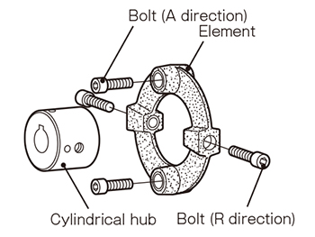
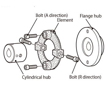
This term indicates the "parallel direction" with respect to the center of the axis on which a coupling is mounted. Miki Pulley calls bolts mounted in the parallel direction with respect to the center of the axis among bolts that fix in place rubber bodies and elements in CENTAFLEX Couplings "A direction bolts" ("A" stands for axial).
-
We distinguish the term that indicates the parallel direction with respect to the center of the axis in the same way for the allowable error as a term for couplings in general by calling it the "axial direction" (sometimes also called the thrust direction).
*There is the radial direction (vertical direction) as a term corresponding to the axial direction (parallel direction).
Backlash
-
Backlash refers to mechanical rattling. It occurs at the points where there is no transmission even if there is rotation when gears are engaged. Accordingly, backlash is inappropriate for machines that require high positioning accuracy.
-
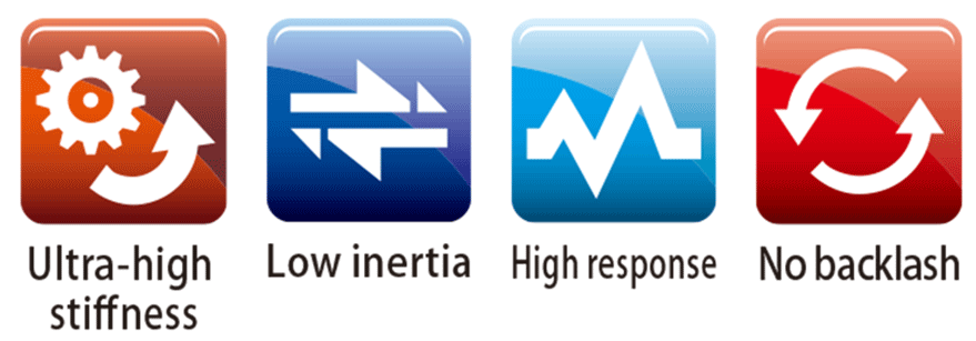
"Completely no backlash" is given as one of the strong points of the SERVOFLEX Couplings in the catalogs of Miki Pulley. In other words, no backlash means that there is no mechanical rattling. Therefore, they are suitable for the high-speed and high precision positioning of servo motors and ultra-precision control applications.
We provide "feature icons" that indicate the function and performance on the coupling production lineup page in catalogs, so please refer to this when making your selection.
Ball screw
-
This refers to "feed screws" in which a ball "rolls" between the valley of the male thread and female screw threads.
-
The rolling motion reduces frictional resistance. Therefore, its strong point is that it is possible to obtain a high efficiency.
Ball screws consist of screw axes, nuts and bolts. However, bolt screws alone cannot transmit power. Accordingly, it is possible to convey the rolling motion of motors into linear motion by linking them to motors with couplings. Consequently, they are widely used in the transferring and positioning of semiconductor manufacturing devices, industrial robots and machine tools.
Black oxide coating
-
This refers to the surface treatment to prevent rust by forming an oxide film on the surface of iron and steel. It is called black oxide coating because the finish is a glossy black. In addition, it is also called "iron tetroxide coating" because it forms an oxide coating.
-
Forming an oxide film produces a treatment that ensures rust does not progress by rusting the surface of iron. it may seem similar to the method in which we prevent influenza by injecting a small amount of the influenza bacteria into our bodies.
To that end, if using or storing for a long time, it is necessary to protect the surface with anti-rust oil.
Please note that there is a danger of rust forming if stored for a long time after purchase.
We use this in the hub surface treatment of the SERVOFLEX Coupling / SFS Model and SERVORIGID Couplings among the products of Miki Pulley. The advantage of black oxide coating is that it is performed with a chemical reaction. Therefore, it does not peel off like plating processing and painting processing treatments. Furthermore, the coating is thin (differs depending on the treatment time), so there is almost no impact on the dimensional accuracy.
CENTAFLEX
-
This is a coupling developed by CENTA Antriebe of Germany with technical cooperation from Miki Pulley.
The product name derives from the "CENTA" of the company name.
-
CENTAFLEX Couplings are classified as motor rubber and resin couplings.
The rubber couplings are those that attenuate and absorb shocks and vibrations by using the elasticity of rubber while resin couplings use the elasticity of resin.
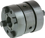
CENTALOCK
-
This is a unique method to completely fix in place spline axes and couplings (cylindrical hubs) in the CENTAFLEX Couplings of Miki Pulley. It fixes in place with the addition of a force around the spline processing part by tightening the clamping screw.
-
Centering location / Spigot joint
-
This is an assembly method that uses convex and concave parts to facilitate alignment by aligning convex areas processed on one part and concave areas on the other part when fastening by aligning the center of parts. This is called inro awase in Japanese with the original meaning of inro being a small container with a long cylindrical shape lowered at the back. Originally, these contained seals and seal stamp pads. However, medicine started to be put into them in the Edo period (1603 to 1868).
-
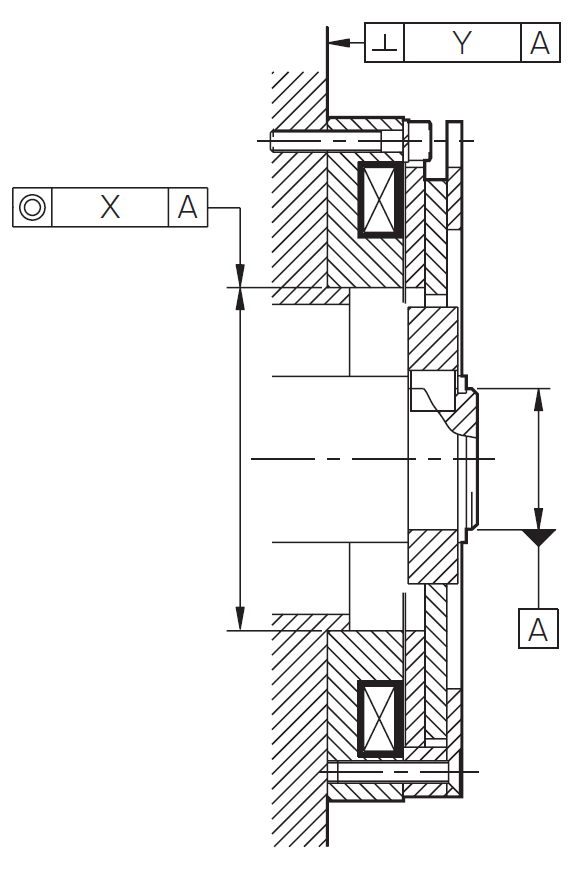
The container and lid are made to fit perfectly. Therefore, it is possible to understand it with the sense of the lid of a tea caddy fitting perfectly with its body in current times. Alignment in which parts fit together perfectly like this is called the centering location or spigot join due to this spigot structure.
We ask that you employ a mounting method with the centering location / spigot joint to ensure that the centering of the two axes in Couplings and the fixing in place of the mounting surface and axis of brakes in Electromagnetic Clutches and Brakes are performed with high precision in the products of Miki Pulley.
ChemSHERPA
-
⇒Please also read the "JAMP" term.
This refers to the new scheme to transmit information on chemical substances contained in products in the supply chain developed by the Ministry of Economy, Trade and Industry. The operating organization of "ChemSHERPA" is the Article Management Promotion Council JAMP.
It is no longer possible to provide support at the company level under the situation in which chemical substance regulations are expanding and strengthening. In addition, the mindset of companies differs even within the same industry. Information between companies is also not shared. Accordingly, the Ministry of Economy, Trade and Industry has developed a common scheme that can be used across supply chains in various industries. This is "ChemSHERPA." This clarifies component information based on common substance lists. It has made it possible to transmit information under the concept of sharing from the upstream to the downstream of supply chains.
Miki Pulley performs investigations on the chemical substances contained in our products to be able to respond to the demands of our customers. For example, we accurately report information learned based on information transmission through supply chains and then provide this in files created with the ChemSHERPA tool.
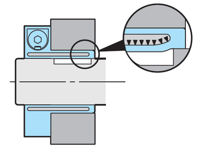
Clamping bolt
-
This refers to the bolts used in clamping hubs. Hubs and axes are fixed in placed by tightening clamping bolts and narrowing the slits processed onto the clamping hubs.
-
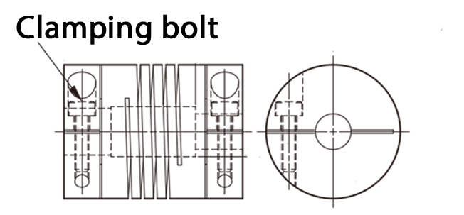
It is possible to securely fix in place hubs and axes by tightening with the appropriate "tightening torque" for clamping bolts.
*Please understand that we use the term "clamping hub" for clamp hubs in the English version of the catalogs of Miki Pulley.
Clamping hub
-
⇒Please also read the "clamping screw" term.
⇒Please also read the "center lock" term.
This refers to a hub to fix in place with spline axes using the function of center locks. We call the cylindrical hubs that use clamping screws in CENTAFLEX Couplings "clamping hubs."
Clamping hub
-
This is the general term for hubs with slits in SERVOFLEX Couplings, STEPFLEX Couplings and STARFLEX Couplings.
-
In addition, the bolts used in clamping hubs are called clamp bolts.
*HELI-CAL Couplings are integrated parts, so do not have hubs. However, the method of fixing in place with axis with a clamping bolt has the same structure.
* CENTAFLEX Couplings have a clamping hub and clamping screw. The concept of fixing in place the hub and axis is the same. Nevertheless, the names are differentiated because the structures are different.
*Please understand that we use the term "clamping hub" for clamp hubs in the English version of the catalogs of Miki Pulley.
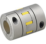
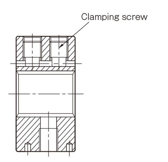
Clamping screw
-
⇒Please also read the "clamping hub" term.
-
⇒Please also read the "center lock" term.
This refers to a screw with a special shape that is inserted into threaded screw holes processed into clamping hubs to fix in place clamping hubs and spline axes by using a center lock in CENTAFLEX Couplings. *Similarly, there are also clamp bolts to fix in place hubs and axes. However, these are used in clamping hubs with slits (e.g. the SERVOFLEX / SFC Model ).
Clock wise
-
This stands for clockwise.
*The opposite is counter clockwise (CCW).
Computer numerical controll lathe
-
⇒Please also read the "Numerical controll lathe" term.
NC stands for numerical control while CNC stands for computer numerical control.
CNCs have reached the present since being developed in the 1970s. This means that there is really no need to separate NC and CNC nowadays. In terms of meaning, it is the same thing.
Counter clock wise
-
This stands for counter clockwise.
*The opposite is clockwise (CW).
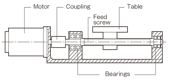
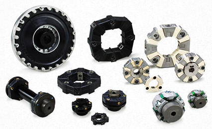
Coupling
-
Couplings are articles that connect axes. They play a role in transmitting the power of machines to the other side. Most of the couplings handled by Miki Pulley are called flexible couplings. These are characterized by the fact they can transmit rotations and power even if the centers of the axes are misaligned.
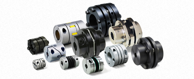
Conversely, there are also extremely rigid couplings with no such flexibility. These are handled under the name of SERVORIGID Couplings" by Miki Pulley.
Damping performance
-
Attenuation is a vibration phenomenon in which amplitude gradually decreases over time. The shorter this time, the higher the attenuation performance. The "high attenuation performance" that is one of the strong points of the STEPFLEX Couplings of Miki Pulley comes because they quickly absorb the vibrations. This is because the elastic part (element) material of the couplings is rubber.
-
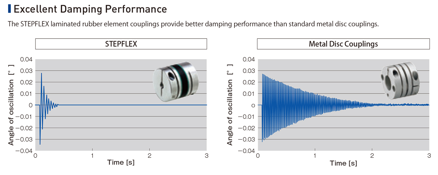
Flexible couplings made with metal for the elastic part are hard in the torsion direction. This means they excel in rotation transmission. However, rubber has better vibration absorption. Consequently, please select the best coupling to suit the precision, performance and use of the machine you require.
Element
-
These are important parts that transmit power in couplings. They are called elements by Miki Pulley. The materials of elements are metals, resins and rubber. They are parts that have the most impact on the performance of couplings (especially the torsional spring constant and mounting error). They are sometimes called "cushioning" in Japanese.
-
In addition, we use different terms for the "spiders" of SPRFLEX Couplings and the "metal coil springs" of BAUMANNFLEX Couplings. However, the functions of these are equivalent to elements.
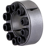
ETP BUSH
-
⇒Please also read the "Pascal's principle" term.
-
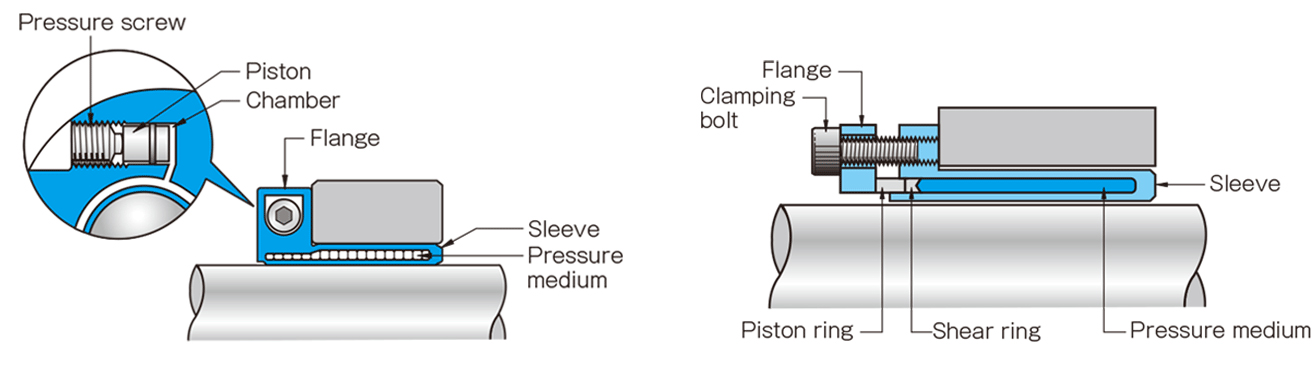
This refers to a friction fastener that fastens the axes and hubs handled by Miki Pulley with the pressurization of a pressure medium. Simply put, an ETP Bush inserted between an axis and hub is a product that expands to fix in place the axis and hub. One of the most unique aspects of the ETP Bushes developed by ETP in Sweden is that it can be called a pressure medium. The pressure medium expands the ETP Bush and is enclosed in the ETP Bush body. Similarly, it has a structure in which the pressure medium is pressurized and the sleeve of the main body expands by tightening a pressure screw or clamping bolt of the body. Although we say expand, it does not deform to the extent that is visible to the eye.
Fastening with a key and keyway that fixes in place an axis and hub is the most typical means of fastening. However, keyway processing on both the axis and hub is necessary for this. Furthermore, the work to insert a hub that has been subject to keyway processing into an axis with a key mounted is very difficult. Therefore, we believe everyone will have experienced the frustration of it biting halfway through without it going smoothly at least once. Insertion is easy with an ETP Bush. Furthermore, the mounting time is just 20 seconds for models that fasten with one bolt. There is even no time to get frustrated.
When we first launched ETP Bushes, we were faced with the doubt of whether there would be slippage by fixing in place with friction force. There is complete peace of mind with key fastening. Nevertheless, if that is the case, the tires of cars and bicycles also cannot be believed. That is because they stop due to friction force. Of course, key fastening has been adopted for many years. Therefore, it is possible to reduce processing costs with keyway processing facilities and there is no problem with key fastening if there is nothing when used.
However, the most unfortunate thing about key fastening is the large rattling that occurs while being used rather than the frustrating mounting. In other words, backlash occurs. There are no keyways on servo motor axes. You probably already know the reason for that. That is because the backlash of key fastening is the great enemy for the high precision movement of servo motors. ETP Bush friction fasteners combine both workability and high precision in the fastening of axes and hubs in this way.
⇒"ETP-E Friction Fastener Operating Principles" Video
⇒"ETP-A Friction Fastener Operating Principles" Video
Export Administration Regulations
-
⇒Please also read the "parameter sheet" term.
EAR refers to the "Export Administration Regulations" in U.S. law. Products and technologies that contain parts originating in the U.S. are subject to these regulations. If they do not contain such parts, they are not subject to the regulations. Accordingly, these regulations are involved in trade around the world. For example, when exporting from Japan to China, products that contain parts originating in the U.S. are subject to the EAR. In other words, even if the U.S. is not the country to which products are being exported, it is necessary to consider the EAR decision.
In this way, products and technologies that contain parts originating in the U.S. are subject to the "re-export regulations" in the EAR when being exported from Japan to other countries. *The fact there are parts originating in the U.S. in Japan means that they were first exported from the U.S. to Japan. When these are exported from Japan to another country, it means that they are being exported again. Therefore, we call this "re-exporting."
Flange
-
This refers to the part that juts out in a brim shape from products like parts with a large flange hub diameter. Alternatively, the parts with such a shape may themselves also be called flanges.
Flange hub
-
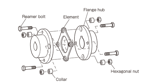
This is one of the hubs for fixing in place the rubber bodies and elements in CENTAFLEX Couplings. The bolts to fix in place the rubber bodies or elements to the flange hub are mounted parallel to the center of the axis onto which the coupling is mounted. Therefore, they are referred to as "A direction bolts" (A is the abbreviation for axial).*There are cylindrical hubs as hubs used as a pair with flange hubs.
-
Flywheel
-
⇒Please also read the "CENTAFLEX" term.
-
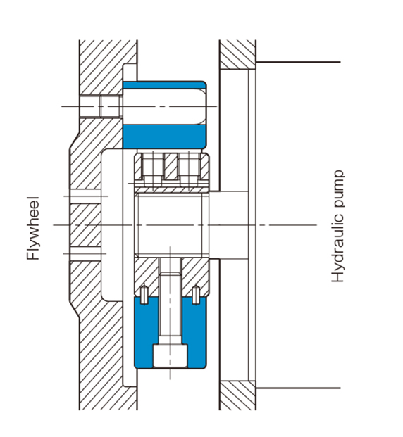
This refers to a disk that stabilizes rotation. Even if the reciprocating motion of a piston generated with an explosion like an engine is transmitted to the rotational movement of a crankshaft without change, the rotation will not be smooth. Accordingly, it is possible to stabilize the rotation with inertia by mounting a flywheel to it.
However, if there is insufficient stabilization with just a flywheel, it is possible to obtain extremely stable rotation by directly mounting a CENTAFLEX Coupling to the flywheel and linking it to the shaft because the CENTAFLEX will absorb the vibrations. In this way, the CENTAFLEX is widely used in mechanisms in which engines of construction machinery (e.g., excavators) or ships and engines connected to propellers serve as the drive source.
Gain
-
This is the ratio of output with respect to the input of voltage, current and power in control systems. The unit is decibels. This is called gain. Alternatively, it can also be called the amplification rate because the input is multiple times the size of the output.
-
It is often possible to hear the phrases "high gain" and "gain adjustment" in motors that rotate at high speed with high precisions like servo motors. In other words, increasing the gain means increasing the output so that it is possible to operate at even high precision and speed. Servo motors now adjust to the optimal gain with auto tuning. However, if the gain is too high, it will go past the target position. Furthermore, it will attempt to return to the target position after going past it. That movement becomes vibrations. This means it is necessary to adjust the gain manually. Gain adjustment includes "position control," "speed control" and "torque control." It is possible to achieve the best high precision and high speed rotation by adjusting to the optimal gain with a combination of these.
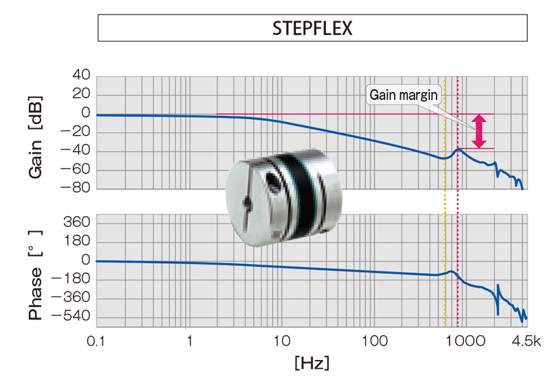
The STEPFLEX Couplings of Miki Pulley quickly attenuate the vibrations generated at that time even if set to high gain. Accordingly, it is possible to achieve stable high-speed control.
⇒"Measures Against Vibrations During the High Gain of Servo Motors" video ☆ We use videos to introduce proposals for solutions that suppress the vibrations generated by servo motors during high gain and the vibrations generated by pulsation during the resonance of stepping motors in place of STEPFLEX Couplings with a high damping performance that use laminated rubber elements from those made of metal such as SERVOFLEX Couplings and HELI-CAL Couplings.
Gantry
-
A gantry is a moveable structure that has the shape of a gate. Accordingly, the gantry mechanism is referred to as a mechanism in which gate-shaped parts straddling two parallel orbits move. You can think of this as being like a pedestrian bridge moving in line with a sidewalk.
SERVOFLEX Couplings are suitable for gantry mechanisms because couplings with high torsional rigidity are required to simultaneously operate and smoothly move two orbits. It is often possible to see gantry cranes in gantry mechanisms. These are cranes that load and unload while moving the cargo of a container ship in a port on a rail.
Hammering
-
This refers to the adjustment of an object with light tapping by a tool hammer. We give an explanation so that you can adjust the flange outer circumference and edge with hammering as a means of centering for the SERVOFLEX Coupling / SFF Model.
Hexagon head bolt
-
⇒Please also see our "Hexagon Head Bolt Shapes and Dimensions" technical document.
-
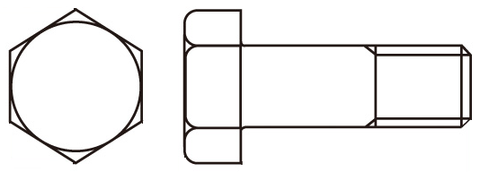
This is the general term for bolts with hexagonal heads. We use spanner-shaped heads that fit hexagon heads when tightening bolts. Hexagon head bolts are used in various ways in the products of Miki Pulley. For example, we have available a type that uses hexagon head bolts in clamping bolts in our Mechanical Axis Lock / POSILOCK products. In addition, hexagon head bolts are used as pressure bolts in the friction fastener hubs of our SERVOFLEX Couplings .
"Hexagon socket head cap screws" are often used together with hexagon head bolts. However, here, we use hexagon heads (hexagon wrenches) when tightening bolts. To that end, it is necessary for hexagon socket head screws to have a much wider space to be able to tighten. If it is difficult to obtain such a space, it would be best to select the hexagon head bolt type.
Hexagon socket head cap screw
-
⇒Please also see the "Hexagon Socket Head Cap Screw Shape and Dimension Standards List" technical document.
-
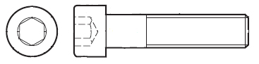
This refers to hex socket head cap bolts. We use hexagonal wrench-shaped hexagon heads that fit hexagonal holes when tightening bolts.
Hexagon socket head cap screws are the part used the most commonly in the products of Miki Pulley. They are used with the name of clamp bolts or A and R direction bolts in various couplings. In addition, we believe they are often used when fixing the products of Miki Pulley to the bases of the machines of our customers.
We also tighten hexagon socket head screws with a torque wrench or torque driver. Furthermore, it is necessary to manage the tightening torque suitable for the strength classification of the screw. If the screws are not tightened at the appropriate tightening torque, they may become loose. Please take care because this may occur regardless of whether they are tightened above or below the appropriate tightening torque. Moreover, Miki Pulley performs special surface treatment and looseness prevention on screws depending on the product for the hexagon socket head cap screws of our couplings . Therefore, please take care when handling them.
You may have realized that we refer to these as bolts in Japanese but screws in English. "Hexagon head bolts" are bolts. In fact, we call everything bolts in Japanese, However, there is a difference between bolts and screws due to their different usage methods in English.
That is because hexagon head bolts are generally used together with nuts. Accordingly, bolts are used together with nuts and those that are not are screws. The typical usage method of these is reamer bolts in our SERVOFLEX Couplings / SFS Model. Here, the customer fixes in place reamer bolts with nuts.
HS code
-
This refers to the code established under the HS Convention given to all items subject to trade. The HS Convention is an international treaty on the Harmonized Commodity Description and Coding System. It is managed by the World Customs Organization (WCO).
When declaring imports and exports to customs in Japan, we enter a nine-digit number corresponding to the cargo we are declaring. This number is called the "harmonized system code." The first six digits of this number are the HS code. Items are classified by the same rules in countries around the world. Therefore, the same number indicates the same item.
The reason why the harmonized system code or HS code are necessary is to find out the tariff rate. Tariffs vary by country. However, the numbers are shared. This means that is possible to know the tariffs of the other country even without knowing the language of that country.
For example, the HS code of Couplings is "8483.60," (The harmonized system code is "8483.60 000".) It is possible to check the harmonized system code on the customs website. If we search for "couplers" from "trade harmonized system" → "export harmonized system item list" → "class 84: reactors, boilers, and equipment and parts equivalent to these" → "item list → list, we can learn the harmonized system number and HS code. There is "clutches and couplers (including universal joints)" in the "8483.60" HS code. Nevertheless, let's check an even more detailed explanation just in case.
Let's look at class 84 in "trade harmonized system" → "tariff rate list explanation / classification rules." "Sleeve joints, flange joints, flexible joints, fluid joints and universal joints (those like hook joints and Oldham joints) included here" is found in the item described for "8483.60." Accordingly, we can verify that this is the HS code for the couplings handled by Miki Pulley.
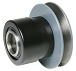
Idler
-
When power is transmitted by a belt and chain, the belt and chain stretch a little while they are being used. This becomes slackness and then generates vibrations and noise. This has an impact on the power transmission.
-
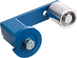
Accordingly, products which eliminate slackness caused by this stretching are called tensioners. The part which is mounted to this tensioner to come into contact with the belt and chain is called an idler.
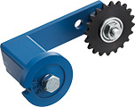
Miki Pulley also handles products with the function of a tensioner. One of these is our ROSTA Tensioner. We have available a RSE model that comes with a "roller idler" and a NSE model that comes with a "sprocket idler."
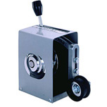
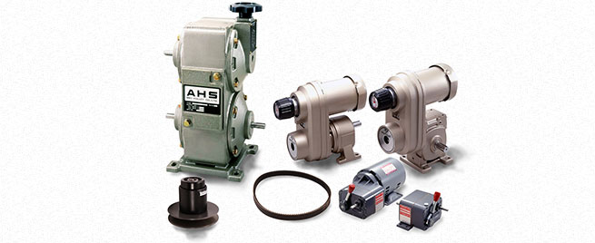
In addition, we have a model that comes with a "tension pulley" (the black part in the figure on the right) with the same function as an idler for our L model of Belt Type Stepless Speed Changer Standalone Items.
International energy-efficiency class code
-
⇒Please also read the 「"motor"」 term.
-

⇒Please also see the 「"Premium Efficiency Motor Specifications List"」 technical document.
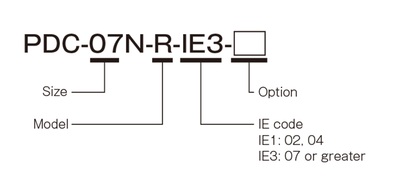
This refers to the three-phase motor efficiency class. IE3 motors are premium efficiency motors.
Inverter
-
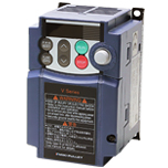
Inverters are devices that control the rotational speed of motors to a stepless speed by freely setting the frequency and voltage of the AC power supplied to the motor. Originally, power conversion devices that alternate direct current are called inverters and devices that convert AC to DC are called converters. Devices that make it possible to control motors by setting this to a circuit in which it is possible to freely set the frequency or voltage have now become known as inverters.
-
When there was no inverter, the rotational speed of the motor was constant, so the rotational speed was changed with a Belt Type Stepless Speed Changer of Miki Pulley. Furthermore, there are regions with 50 Hz and 60 Hz in Japan and various power situations around the world. Therefore, schemes in themselves are necessary to obtain a rotational speed that suits your situation.
Accordingly, with the advent of inverters, it is possible to freely set the rotational speed of motors. Therefore, it has become possible to combine increasing the speed of one task while decreasing the speed of another task. Furthermore, this has also been adopted in products using various motors in addition to industrial machinery. "Inverter air conditioners" and other products have been launched. Inverters have also evolved up to now. Therefore, the standard specifications take into account the environment in terms of also contributing to energy saving and a reduction in CO2. This is in addition to the advantages of inverters of making it possible to obtain a high motor efficiency and having few rotational vibrations even at low speeds.
The Inverters of Miki Pulley come with functions optimal for a variety of small capacity needs with our unique design concept cultivated over many years of experience. It is possible to set the output frequency up to 400 Hz. Furthermore, an automatic energy saving function is equipped as standard.
Involute curve
-
The involute curve refers to a curve drawn by the tip of a thread that can be made when unwinding while holding the tip of a thread from a spool of thread. The involute curve is one shape of a spline processed groove in the spline fastening adopted in the CF-H mode of CENTAFLEX.
-
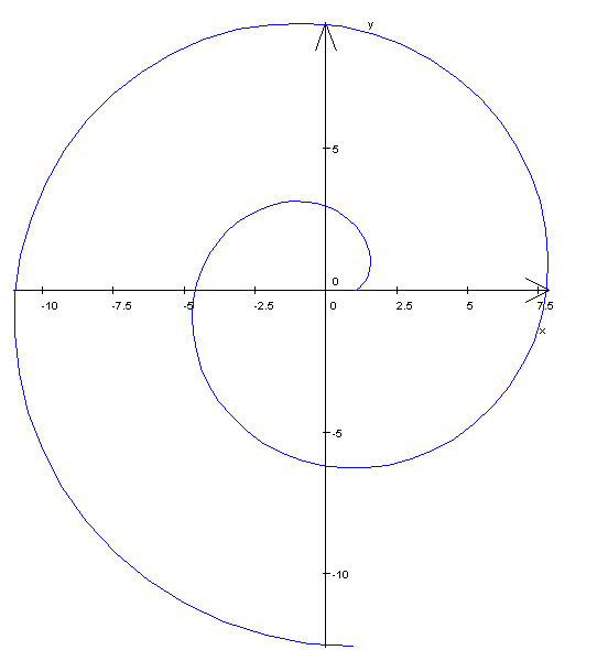
We call a spline processed in this way an involute spline. The advantages of involute splines include the fact they have a high power transmission capability and are relatively easy to process.
JAMP
-
⇒Please also read the "ChemSHERPA" term.
This refers to the Joint Article Management Promotion-consortium (JAMP). It was launched in September 2000 to create a mechanism to appropriately manage information on chemical substances contained in products and to smoothly transmit information in supply chains. Article: This is another name for parts and molded products.
The following advisory committees have been established and are active in JAMP:
(1) Management Guideline Technical Committee: This creates and disseminates guidelines to appropriately manage the chemical substances contained in article.
(2) Dissemination Committee: This disseminates ChemSHERPA.
(3) Tool Committee: This maintains and improves ChemSHERPA creation support tools.
(4) Controlled Substances Committee: This grasps the trends in regulations/standards and develops controlled standards/substances lists.
Japanese Industrial Standards (JIS)
-
This refers to the Japanese Industrial Standards. These are the national standards of Japan. JIS stands for Japanese Industrial Standards. Accordingly, these standards are called JIS or the JIS standards. The name of these standards in Japanese changed on July 1, 2019. However, the English name remained the same.
-

Shortly after the end of the war in 1945, the Industrial Standardization Law was enacted with the aim of promoting the standardization of industry in Japan in 1949. Incidentally, Hideki Yukawa was the first Japanese winner of a Nobel Prize in 1949. In addition, Aoi Sanmyaku was a hit movie and wooden refrigerators (not made of metal) were hit products at this time. We can say that the rapid growth of Japan started around this time with the inclusion of the enactment of the Industrial Standardization Law. The total number of JIS standards has reached 10,773 as of the end of March 2019.
The JIS are national standards, but who makes them? Standards are mainly enacted and revised by the cabinet minister in charge. Looking at this trend, the drafting and creation of these standards is the work of government officials. In fact, stakeholders such as private organizations create the drafts of these standards. In other words, standards relating to rubber are created by rubber companies. Of course, various related people in universities and public organizations in addition to private companies come together to create standards. It is possible to check the names of the companies and organizations that make these standards at the end of the JIS standards.
As we touched upon earlier, there is a considerable number or enactments (turning a draft into a formal standard), revisions (reviewing standards and changing their content) and abolitions (removing from the standards) almost every month with the JIS standards. This is because standards are supposed to be reviewed within at least five years from their date or enactment or revision. Consequently, since the old version of the JIS standards loses its effectiveness, always remember to apply the latest version. It is possible to check information on the enactment and revision of standards on the websites of the Japanese Industrial Standards Committee and the Japan Standards Association. In addition, it is possible to search and browse the latest JIS standards with the Japanese Industrial Standards Committee. Furthermore, it is possible to purchase JIS standards (paper or electronic version in Japanese or English) with the Japan Standards Association.
It is possible to tell whether a JIS standard is the latest version because it comes with the four digits of the year in which it was enacted or revised in the JIS number. This JIS number is a unique number. For example, it is JIS B 1176:2014 for hexagon socket head bolts. The B in the number is a single letter of the alphabet that represents the category code. In this case, it is for "general machinery." The next number 1176 is a four-digit number that represents the classification number. We have published excerpts taken from the main text of JIS standards relating to the products of Miki Pulley, such as the hexagon socket head cap screw standards we just mentioned, in the technical documents on the website of Miki Pulley.
Light Emitting Diode
-
This stands for light emitting diode. In addition, semiconductors that contribute to the light emission of LEDs (light emitting diodes) - in other words semiconductors with the properties to emit light when current flows - are called LED chips.
-
LED chips are made with laminated film (e.g., P layer, N layer and light emitting layer) formed in the growth process in which gas (e.g., nitrogen or gallium) is emitted onto a sapphire substrate to grow crystals. Furthermore, LED chips are completed by adding electrodes and a protective film onto the lighting emitting layer. "P type semiconductors" of LED chips are in a state lacking electrons ( a state with many electron holes). "N type semiconductors" of LED chips are in a state with many electrons. The "PN union" with P type semiconductors and N type semiconductors is the basic structure.
When forward voltage is applied to LED chips here, electrons and electron holes move and collide. When they collide, they combine (this is called re-combination). When electrons with high energy collide and recombine, the energy decreases. Therefore, the difference in this energy is converted to light. This is the mechanism by which LED chips emit light. LED chips that emit this light are arranged on a printed circuit board or similar and can then be handled as a light source for many parts. This is called an LED module. Furthermore, arranging LED modules with lighting devices and combining them with many parts leads to the light source units of LED lighting fixtures.
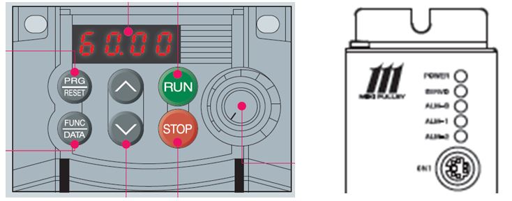
Red LEDS were the first to be invented in the world; these were then followed by yellow-green LEDs. Next, Mr. Akasaki, Mr. Amano and Mr. Nakamura of Japan invented blue LEDs. They won the Nobel Prize for that in 2014. The creation of the three primary colors of light by the invention of blue LEDs has made it possible to manufacture white LED lighting. This is used in the monitors that display the rotational speed of inverters and the driver display panels of linear shaft drives for the products of Miki Pulley.
Loss of synchronism
-
This is the phenomenon in which stable operation becomes impossible due to the phase difference between two machines increasing in synchronous control. The cause of the phase difference increasing comes from a shift in synchronization due to a heavy load suddenly being applied or the accumulation of control accuracy errors.
For example, to synchronously operate two conveyors installed separately, it is best if the rotational speed of the drive motor of each is the same. To achieve this, we detect/compare the rotational speed output by each conveyor and then send a signal correcting the difference in the rotational speeds to the drive motors. The part that corrects the difference in the rotational speeds at that time is the controller.
The tach generator is one piece of equipment widely used to detect the output rotational speed. Tach generators generate a voltage proportional to speed. However, it is an analog type, so its accuracy is not great. Rotary encoders have been used in place of these until now.
Machining center
-
⇒Please also read the "Numerical controll lathe" term.
MC stands for "machining center". Processing is performed with automatic control for NC machine tools (e.g., NC lathes). However, it is necessary to replace the edged tools and other tools (e.g., bits) manually.
Machining centers automate this work. This makes unmanned processing possible. The words themselves of MC and NC are similar in terms of the automation of processing. Therefore, there is a tendency to think they have similar meanings. However, they mean completely different things.
Mass
-
⇒Please also see the "SI Unit List and Conversion Table" technical document.
This refers to the volume of objects themselves not affected by gravity. This is expressed in kilograms (kg) in the SI unit system. Universal gravitation acts between the earth on objects. In addition, since the earth is rotating, the resultant force of this attraction and centrifugal force is "gravity." We know that weight is slightly lighter on the equator than at the Artic. This is because the gravity is different due to the impact of the centrifugal force.
In the past, we used the gravity unit system (conventional units) and expressed this as weight [kgf or kg weight]. We know that gravity is working by looking at this unit. However, this is inconvenient if the weight differs depending on the location. For example, the value of the gold of people living in a country near the Artic would be less that in a country on the equator because it would weigh less. Moreover, the gravity is one sixth of that of the earth on the moon. Accordingly, the value on weight scales would also be one sixth. There may be people happy at that, but you should know that it does not mean that you have lost weight.
Accordingly, we have unified to an international unit system (SI unit system) that is not affected by gravity in place of the gravity unit system. Mass [kg] has come to be used. However, although it is only natural, the values for weight and mass will differ by the amount of gravity. Well then, let's look at those differences.
Objects are pulled toward the center of the earth by the gravity that we mentioned earlier. Therefore, the relationship is weight = mass × gravity acceleration. In addition, if an object is dropped, it will continue to accelerate at a constant acceleration. Therefore, this is called the gravitational acceleration. It is expressed as 9.8 m/sec2. Furthermore, force = mass × acceleration according to Newton's Second Law of Motion. This means that the force generated by acceleration at 1 m/sec2 on an object with a weight of 1 kg is referred to as 1 N (Newton).
Consequently, 1 kgf (weight) = 1 kg (mass) × 9.8 m/sec² (gravity acceleration) = 9.8 kg m/sec² =9.8 N (Newton). This means that 1 kgf=9.8 N. We can say that gravity of 9.8 N acts on an object with a weight of 1 kg from this equation.
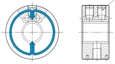
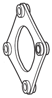
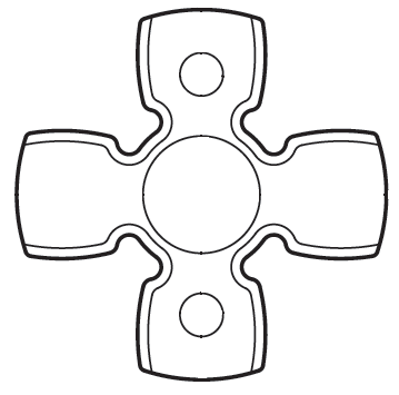
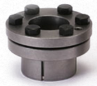
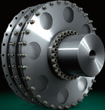
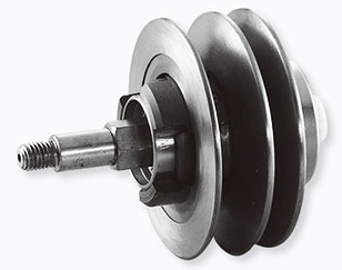
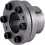
Membrane
-
We usually call this a membrane. However, Miki pulley uses the term "membrane system" for our CENTAFLEX Couplings. The membrane in this case means a "thin board." The large circular part with multiple round holes in the image is the membrane. Bending this membrane can absorb mounting errors. This is called the membrane method by Miki Pulley.
-
CENTAX Couplings are a product related to CENTAFLEX Couplings. They are used for generators and the main or auxiliary engines or ships. We have not posted CENTAX Coupling product information on our website. Nevertheless, you can view the product lineup (for ships) in our general catalog by downloading our CENTAFLEX Coupling catalog. This will give you a brief page introducing CENTAX Couplings.
Miki pulley
-
⇒Please also read the "pulley" term.
⇒Please also see the "stepless speed changer" term.
-
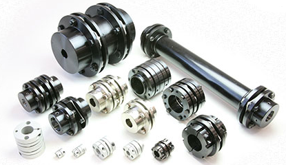
Miki Pulley is a comprehensive manufacturer of transmission and control equipment. We develop, manufacture and sell couplings, ETP Bushes (friction fasteners), electromagnetic clutches and brakes, and other products.
Miki Pulley was established in Kawasaki in Kanagawa Prefecture as Miki Seisakusho in October 1939. We obtained a patent for belt-type stepless speed changers in 1954. We then started manufacturing and selling them under the name of Miki Pulley's Stepless Speed Changers. These speed changers further spurred on technical innovation in Japan and played a major role in the industrial world after that. We changed our name to Miki Pulley Co., Ltd. from this product name in 1966.
After that, we expanded our range of products to include couplings, electromagnetic clutches and brakes, and then DC motors and inverters. We continue to support the driving force of all kinds of machines. The logo of Miki Pulley that we currently use was created to symbolize the three concepts of "changing speed", "determining position" and "conveying rotation" that are the features and performance of the products of Miki Pulley like this.
⇒"Miki Pulley Company Profile" video
⇒"What Kind of Company is Miki Pulley?" video
Moment of inertia
-
⇒Please also see the "Moment of Inertia J Calculation Equation and Formula List" technical document.
⇒Please also see the "Moment of Inertia J Simplified Chart" technical document.
These refers to the degree of ease or difficulty in rotating articles. If the moment of inertia is large, it will be difficult to stop. For example, if the moment of inertia is large in a machine that repeatedly goes forward and reverses, it will have a poor response to movement when starting and stopping. Consequently, this will have an impact on the positioning accuracy.
The moment of inertia is the value that is indicated by the product of the mass [M] of the rotating body (kg) and the square of the radius [R] of the rotating body (m). Furthermore, if angular acceleration is applied to the moment of inertia, it results in rotational torque. It is also possible to calculate the characteristic vibration from the moment of inertia and the torsional spring constant. In this way, the moment of inertia is widely utilized in machine accuracy and power calculations. This means it plays a very important role.
Motor
-
⇒Please also see our Premium Efficiency Motor Specifications List technical document.
-
⇒Please also see our Premium Efficiency Motor Nominal Efficiency List technical document.
This is a device that converts electrical energy into rotational energy. It generates rotation by using the attracting and repulsing forces of the N and S poles of an electromagnetic (a magnet is formed when current flows using a coil wound around an iron core). This is called an electric motor. The formal name of the commonly used three-phase motor is a "single-speed three-phase cage-shaped induction electric motor." It is said that the power consumption of three-phase motors accounts for more than 40% of the total power consumption in the world. This shows how much motors are used.
It is extremely important to reduce the power consumption of motors from the viewpoint of energy saving. Accordingly, an "efficiency class (IE code)" of motors has been prescribed in the IEC standards and JIS standards. "High-efficiency" motors have come to be used. IE1 is the standard efficiency, IE2 is high efficiency and IE3 has been updated as premium efficiency. Furthermore, super premium efficiency is also under consideration.
*IE is the abbreviation for "International Energy-efficiency Class."
*Premium efficiency is stipulated for motors with an output of 0.75 kW or more.
Miki Pulley can provide premium efficiency motors for the three-phase motors used in belt-type stepless speed changer units.
Non-ferrous metal
-
This is the generic term for metals other than iron. Aluminum, nickel, zine, magnesium, gold, silver and bronze are non-ferrous materials, so all Olympic medals are non-ferrous metals.
The big difference between ferrous and non-ferrous metals is whether or not they stick to magnets. Only a few metals other than iron stick to magnets (e.g., cobalt and nickel). What is the main difference between aluminum and stainless steel - both of which do not stick to magnets - among the same non-ferrous metals? That is the weight (specific gravity). It is well-known that the specific gravity of iron is 7.8. However, the specific gravity of stainless steel is also 7.8. Meanwhile, the specific gravity of aluminum is 2.7.
It is for this reason that we use light aluminum alloy hubs in the SERVOFLEX Couplings / SFC Model, STEPLFLEX Couplings, STARFLEX Couplings, SPRFLEX Couplings and BELLOWFLEX Couplings of Miki Pulley. Reducing the weight of the couplings reduces the moment of inertia. That makes it possible to improve the responsiveness of machines. This makes even more accurate precision control possible.
Numerical controll lathe
-
⇒Please also read the "Computer numerical controll lathe" term.
Lathes that automatically process with numerical control in place of cutting performed manually are called NC lathes. The lathes that automatically process with numerical control by computer in particular among NC lathes are called CNC lathes.
This numerical control is called "NC." Accordingly, machine tools that perform numerical control are also called NC machine tools in addition to lathes. NC lathes appeared in the 1950s. They later evolved into lathes equipped with a servo mechanism. Today, it is possible to perform multiple processing at the same time and with high precision. NC lathes also play a big role in the production plants of Miki Pulley. Therefore, they are an indispensable machine tool for us.
Parameter sheet
-
⇒Please also read the "EAR decision" term.
We make a decision on whether an export license is required when exporting cargo (products) or when providing technologies (programs) to foreign countries. This is to prevent passing on cargo and technologies that can be converted to arms and military use to those who may endanger the security of the international community. The "parameter sheet" is also sometimes called a "parameter certificate."
When a customer exports a product or machine, the decision of whether or not it is necessary to apply for an export license is made by the customer. However, it is difficult for customers to make a decision about the products of Miki Pulley. Therefore, we make decisions for the our products in advance and then publish them in "Parameter Sheet Issuance" on our website.
The content of these decisions is whether or not a product is subject to the "List Regulations" or "Catch-all Regulations" established by law. The "List Regulations" make a decision about whether something applies to "Export Trade Control Ordinance Annexed Table 1" or items 1 to 15 in "Foreign Exchange Ordinance Annexed Table." The "Catch-all Regulations" make a decision about whether something applies to "Export Trade Control Ordinance Annexed Table 1" or item 16 in "Foreign Exchange Ordinance Annexed Table." In addition, Miki Pulley also makes a decision in regards to the US re-export regulations (EAR decision).
Pascal's principle
-
⇒Please also read the "ETP Bush" term.
-
This is the principle which says that the pressure received at one point is applied to all other points at an unchanged strength when a fluid (non-compressed) is put into an airtight container. It is also possible to say that the pressure of this fluid is equal at all points in the container for this.
"U-shaped pipes" with different sized pipes on the left and right are frequently used as an example when explaining Pascal's principle. For example, let's say that the area of the pipe on the left side is 1 and that it is 5 on the right side (units omitted). If we press the left side with a length of 10, the right side will push up by just 2. In addition, if we apply a weight of 3 to the left side, the right side will not balance unless a weight of 15 is loaded onto it. The moving length is inversely proportional to the area and the weight is proportional to the area. Hydraulic jacks use this principle. These make it possible for the person to lift up a car. The number of times at which the jack is moved (length) to that degree will be large.
However, the ETP Bush friction fasteners of Miki Pulley also use this Pascal's principle. The sleeve part of the ETP Bush where the axis and hub comes into contact has a sealed structure. When the pressure medium here is pressurized with bolts, it is transmitted to all points at an unchanged strength. Therefore, the pressure is evenly transmitted to the axis and hub. Accordingly, the sleeve will become deformed if there is a keyway or notch on the part at which the axis and hub comes into contact with the sleeve of the ETP bus. In addition, even if the length of the contact between the axis and hub is not enough, the sleeve will also become deformed in the same way. Therefore, the length of the axis and hub is designed in principle so that it is used over the entire length with respect to the sleeve. Please take care because there is a danger it may become impossible to remove the ETP Bush if it becomes deformed.
prime mover
-
This is the name of the part that moves machines like motors, pumps and engines. Mounting a coupling to the axis on the motor side means the same as mounting it on the motor axis.
Pulley
-
⇒Please also read the "Miki Pulley" term.
-
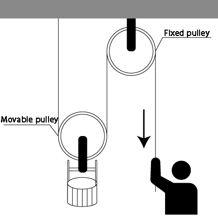
⇒Please also see the "stepless speed changer" term.
This is the term for pulleys. Pulleys were installed on wells with a rope then hooked to them so that a rope to which was tied a pail that lifted up water could easily be pulled up with little force in wells in the olden days. The shape of such pulleys looked like the shape of belt type stepless speed changers / single units. In addition, the invention of belt-type stepless speed changers allowed our firm to develop tremendously. This is the origins behind the name of our company - Miki Pulley.
Radial
-
In general, radial means "a radiating pattern." However, Miki Pulley uses the term to indicate the "vertical direction" with respect to the center of an axis to which a coupling is mounted.
-
In addition, we call bolts mounted in the vertical direction with respect to the center of the axis among the bolts that fix in place rubber bodies and elements "R direction bolts" (R is the abbreviation for radial) for CENTAFLEX Couplings. For example, radial tires used with the same meaning are called such because a metal wire in the tire is wound in the vertical direction with respect to the direction of rotation.
*There is an axial direction (parallel direction as a term corresponding to the radial direction (vertical direction).
Resonance
-
Adding vibrations equal to the characteristic vibration frequency of a vibrating body produces a phenomenon in which the range of those vibrations increases. This phenomenon is used in electrical or mechanical cases. The rattling and large shaking during the drying of a washing machine comes from the resonance phenomenon. The phenomenon in which bridges shook greatly due to wind very long ago was also due to resonance. In addition, the resonance phenomenon caused by the gain adjustment of servo motors in electrical systems is called "oscillation." Furthermore, in the case of sound, the same phenomenon is called "resonance." When a tuning fork placed in a resonance box is rung, a tuning fork in a same size resonance box that is separated from it will also ring. This is the same principle in action.
-
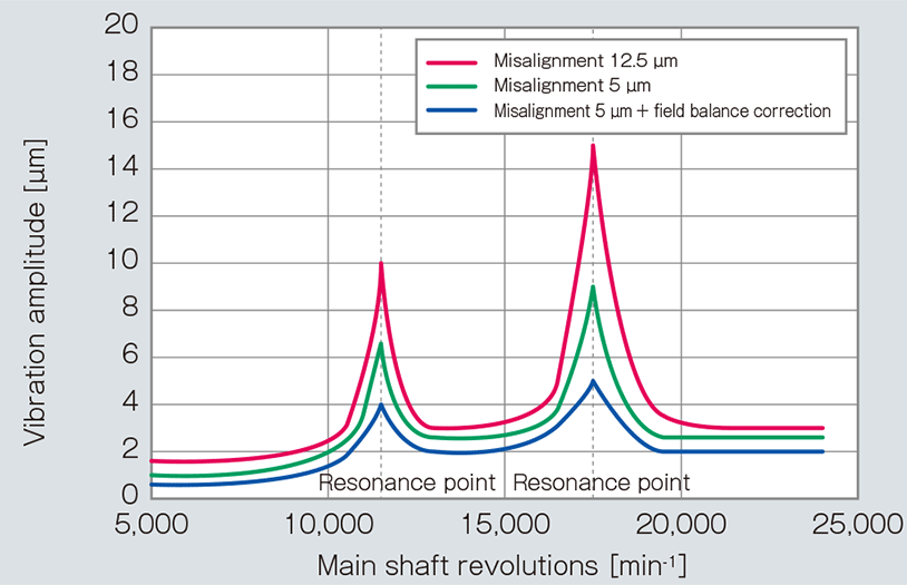
However, in the case of mechanical systems, resonance generates large vibrations across the entire machine. This is a serious problem. It is necessary to calculate the characteristic vibration frequency of the entire mechanical system made by combining various machines to prevent resonance. The torsional spring constant of couplings also has a great impact on the characteristic vibration frequency. Therefore, this is also one means of changing the coupling. For this reason, the coupling specifications tables in the catalogs of Miki Pulley give the torsional spring constant.
⇒"Measures Against Vibrations During the High Gain of Servo Motors" video
⇒"Measures Against Vibrations During the Resonance of Stepping Motors" video
☆ We use videos to introduce proposals for solutions that suppress the vibrations generated by servo motors during high gain and the vibrations generated by pulsation during the resonance of stepping motors in place of STEPFLEX Couplings with a high damping performance that use laminated rubber elements from those made of metal such as SERVOFLEX Couplings and HELI-CAL Couplings.
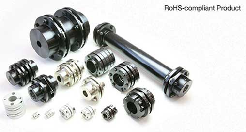
Restriction of the use of certain hazardous substances in electrical and electronic equipment
-
The RoHS Directive is a directive that restricts the use of harmful substances. The Restriction of the use of certain Hazardous Substances in electrical and electronic equipment (RoHS Directive) is a revision that took place on July 1, 2006 of the first directive that came into effect in February 2003 in Europe.
-

The purpose of this directive is to restrict (below the allowable concentration) the use of harmful substances in electrical and electronic equipment in the EU market. The aim is to ensure that chemical substances harmful on the environment and the human body are not exposed to the natural environment as a result. The use of six substances is prohibited by this directive: lead, mercury, cadmium, hexavalent chromium polybrominated biphenyl (PBB) and polybrominated diphenyl ether (PBDE). Accordingly, although the RoHS Directive is a European Law, it affects products that are imported into the EU. Therefore, similar regulations have also been sought in Japan.
The "Revised RoHS Directive (RoHS2) came into effect after that on July 21, 2011. Furthermore, four phthalate esters were added as restricted substances on June 4, 2015 brining the total number of substances banned to ten. These are diethyl hexyl phthalate (DEHP), butyl benzyl phthalate (BBP), dibutyl phthalate (DBP) and diisobutyl phthalate (DIBP). The restriction on including these substances in products came into effect on July 22, 2019. At the same time, the equipment subject to this directive will expand to also include medical equipment and control equipment.
Miki Pulley is also promoting the provision of products that do not contain restricted substances. Together with this, we display a mark on our website and catalogs for various products that comply with the RoHS Directive.
You can also download a RoHS Directive Conformity Certificate from our website, so please use that. ⇒Click here to download the RoHS Directive Conformity Certificate.
Rigid coupling
-
This refers to couplings which have a structure with no element that absorbs the misalignment of two axes unlike flexible couplings.
-
Miki Pulley handles SERVORIGID as rigid couplings. There is no part that bends. Therefore, they can transmit a large torque. In other words, they have the advantage in that the torsional spring constant is very high. For this reason, if we compare them with a flexible coupling transmitting the same torque, it is possible to reduce the size of the outer diameter, so it is also possible to reduce the moment of inertia. However, it is necessary to perform centering of the two axes with as high a precision as possible.
Most of the couplings of Miki Pulley are flexible couplings. However, we also have available rigid couplings called SERVORIGID to suit the needs of our customers in this way. Therefore, please consider the various advantages of each and then select the optimal coupling for you.
Safety factor
-
⇒Please read the 「"service factor"」 term.
SCARA robot
-
This is an industrial robot with arms that move horizontally. It is also called a horizontal articulated robot. SCARA is the acronym for "Selective Compliance Assembly Robot Arm."
SCARA robots basically have three types of rotation movement and one type of vertical movement. The rotating parts are lined up horizontally. Therefore, the strength of the axis of the robot is that it has high rigidity in the vertical direction and flexibility in the horizontal direction. These robots are suitable for work such as pushing in parts.
Self-locking
-
This is also called a self-lock mechanism. It refers to a self-holding mechanism for products. For example, a screw jack is used when repairing a car. However, if there is no self-locking mechanism when lifting it up to a certain height, the car will fall down.
-
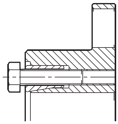
There is a self-locking mechanism in the friction fastener hubs of the SERVOFLEX Couplings among the products of Miki Pulley. When you tighten the pressure bolt in the joint between the friction fastener hub and axis, the sleeve is pressed down and the surfaces slanted with the sleeve and hub come into contact to hold the product in place with the "wedge effect." However, the slanted surfaces will not easily separate even if you loosen the pressure bolt to release and remove the joint. Such a phenomenon or structure is called a self-locking mechanism by Miki Pulley.
The self-locking mechanisms of the products of Miki Pulley such as SERVORIGID Couplings and Posilocks in addition to SERVOFLEX Couplings are not complete locks. Please take care because the joint with the axis may be released at the same time the bolt is loosened.
Service factor
-
⇒Please also read the "torque" term relating to this content.
-
Simply put, this is the value arrived at by dividing the standard value by the maximum value assumed in the design. For example, if the standard value is a torque of 100 Nm when the product breaks and loses its function and the maximum value assumed in the design is an allowable torque of 50 Nm applied to the product, the service factor (safety factor) is 2. In other words, if the allowable torque of a product is listed in the catalog, it becomes double the safety factor up to the breakdown of the product in reality. If the safety factor is 1, the product breaks down when the allowable torque is reached.
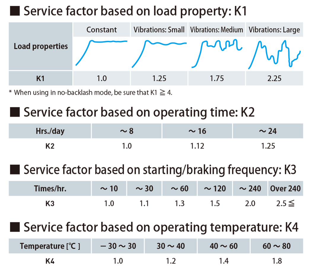
For example, with STARFLEX Couplings, we obtain the torque value [Ta] actually applied to the coupling and then multiply multiple service factors (called the correction factors here) obtained according to the conditions to obtain the correction torque [Td]. Next, we select a size so that this correction torque [Td] is equal to or less than the normal torque [tn] of the STARFLEX Couplings.
Next, the maximum torque [Tm] set to twice the normal torque is determined for the STARFLEX Couplings. The torque at which the coupling breaks is determined by having a safety factor several times the maximum torque. In addition, unexpected events such as impacts may occur in practice. This means a considerably large torque may be applied at such times. However, we have set a safety factor with a margin so there will be no damage even in such a case. Each safety factor is taken into account every few stages so that it is possible to use with peace of mind like this.
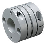
SERVOFLEX
-
These are products of Miki Pulley. It is the product name of metal plate spring couplings. As the name implies, SERVOFLEX Couplings have been developed for the high-speed and high-precision positioning and ultra-high-precision control applications of servo motors and similar. While achieving high rigidity, high torque, low inertia and high responsiveness, they possess the characteristic of being flexible in the twisting direction, step direction and axial direction. There is absolutely no backlash with these products. Furthermore, "SFC," "SFS," "SFF," "SFM and "SFH" models are available according\ng to differences in the allowable torque and rigidity.
-
The basic structure of this product is a plate spring (element) inserted between hubs. The specifications vary depending on the number and shape of the plate springs and also their position (single or double element). In particular, their rigidity is very high. Therefore, the allowable error is extremely small. However, if a spacer is set up between the hub and the leaf spring, the allowable error can be increased.
Solid lubricant coating
-
This refers to processing in which a solid lubricant is turned into a paint with this coat and made into a film. In addition, solid lubricants are used to improve lubrication by reducing the friction and wear of points where oil cannot be used. This is used in the surface treatment of clamping bolts of the SERVOFLEX Couplings / SFC Model and clamping bolts of the F type/stainless steel specifications of Mechanical Axis Lock - POSILOCK / PSL-K Model.
In general, when tightening bolts, we apply lubricant to the screw threads of bolts. However, the coefficient of friction varies depending on the composition of the lubricant. Therefore, variations arise in the tightening torque. Alternatively, there is a danger an excessive axial force may arise and lead to the clamping bolts and couplings becoming damaged. Furthermore, if lubricant enters between the couplings and the axes, slipping may occur. This may adversely affect the transmission torque.
Therefore, we perform surface treatment using a solid lubricant to keep the tightening torque constant and also to prevent the lubricant from flowing. Furthermore, fixation lubrication film treatment is suitable for the surface treatment of bolts because it is possible to perform treatments with large quantities easily.
Stainless steel
-
This refers to an alloy containing at least 10.5% of chromium with a core component of iron (at least 50%) in the international definition. In general, this is referred to as "stainless steel." Stainless means it does not rust. However, it does also seem to be able to rust under specific environments and usage conditions. Therefore, stainless steel is actually best remembered as steel that is highly resistant to rusting and corrosion. In addition to its rust resistant properties, it is also strong despite being heat resistant and easily processible.
-

The material code for stainless steel in the JIS standards is "SUS." This comes from the abbreviation of "Steel Special Use Stainless." In other words, SUS is not understood everywhere around the world. A comparison table with the ISO and similar is posted on the website of the Stainless Steel Association for reference.
If chromium is added to iron, the chromium combines with oxygen to form a light protective film on the surface. This protective film is called passive film. It prevents the progress of rust. Furthermore, the film is tough even though it is thin. The film is automatically generated if there is oxygen even if broken.
SUS304 containing at least 18% chromium is the most widely distributed among stainless steels. This is also called 18 chrome steel. Its strong points are that it is much more resistant to rust and corrosion with corrosion resistant, acid resistant and anti-corrosiveness properties compared to other stainless steels.
SUS304 is used in the elements of SERVOFLEX COUPLINGS and the sleeves and other parts with F type/stainless steel specifications of the 3000 model for HELIC-CAL Couplings (displayed as SUS304 equivalent) and the Mechanical Axis Lock - POSILOCK / PSL-K Model.
Standardization
-
Standardization isdefined as follows in the JIS standards (JIS Z 8002): "This is the act of establishing descriptions to be shared and used repeatedly with the aim of obtaining the best order in a given situation in relation to real or potential problems." To put it simply, when the goal arises to eliminate variability and increase work efficiency for problems with variability in work, this is the standardization of work by preparing work manuals for that and ensuring that everyone is aware of them.
For example, if there are variations in the way drawings are drawn, the people processing items may finish them with the wrong dimensions. This includes cases such as when the dimensions of the parts that should be processed are not clearly described or when those dimensions do not appear without making a calculation. If the processing dimensions are clearly described from the standard surface, anyone can look at them and process them without mistakes. In other words, it is best if there is a manual describe the way to draw drawings so that all those preparing such drawings produce the same drawings.
"Make sure to draw the dimension lines from the reference surface to be processed and then describe the processing dimensions accurately when you draw a drawing." Just by making simple drawing manuals based on this idea, it is possible to prevent mistakes and shorten the time to draw them. Therefore, these are effective for the those drawing and inspecting them in addition to those processing them. As a result, it leads to being able to provide products with a stable quality to customers. Please also remember to obtain the best effect with as little work as possible.
Furthermore, once you have created a manual, you will not need to do it again (although it will be necessary to review it). Therefore, if you have the time to say that it is a waste of time to prepare a manual, actually preparing a manual is much more effective. The key is to proceed with "visualization" in which you make it possible for anyone to immediately see the manual that has be created the next time. If you do not do this, it will be a waste of time.
Stepless speed changers
-
⇒Please also read the "pulley" term.
⇒Please also see the "Miki Pulley" term.
-
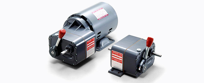

This refers to a machine that can change speed without steps. Conversely, the three-step gear of a bicycle is a speed changer with steps like three steps. Miki Pulley handles various stepless speed changers. These include belt systems which transmit with a pulley and belt like our belt-type stepless speed changers, mechanical systems like our Zero Max Stepless Speed Changers and electric systems like our DC motors and inverters.
Strain
-
⇒Please also read the "tensile strength" term.
This refers to the value obtained by dividing the value at which a material is stretched when a tensile force is applied to a material (the difference between the length after being stretched and the original length) with the original length. This value is expressed as a percentage. *Forces applied to materials are not limited to the tensile force. However, we give an explanation with the tensile force to make it easy to understand.
There are probably many people who think of "strain gauges" when they hear the word "strain." Strain gauges can be called a sensor affixed to a structure for example to measure the extent of the strain when a force is applied to that structure. Why do we seek "strain?" When a tensile force is applied to a material it becomes a plasticity region in which the material is deformed from the elastic region. Eventually, it will break. In other words, it is very important to measure at what force can be applied to a structure before it becomes deformed or breaks. it is possible to display the amount of strain with voltage by measuring this with a strain gauge. Therefore, numerical management becomes possible. Accordingly, we seek strain to avoid deformation and destruction of structures.
In this way, we can obtain strain from the difference in the length that has been deformed due to a force being applied to a material. However, "stress" (the force per unit area) is generated inside the material at this time. The relationship between this strain and stress is stress = strain × longitudinal elastic modulus from Hooke's law.
There are different types of strain. In addition to the tensile strain we mentioned earlier, there is compression strain, elastic strain, plasticity strain and shear strain. The type changes depending on how the load is applied. Furthermore, there are also vertical and horizonal strains. When a material is pulled, it extends out in the direction at which the load is applied (axial direction). However, the perpendicular direction becomes thinner and shrinks with respect to that. This strain in the axial direction is called longitudinal strain and strain in the perpendicular direction is called transverse strain. The ratio of the longitudinal and transverse strain is called Poisson's ratio.
We use strain to describe noise strain and social strain in everyday usage. If we look at the Japanese kanji for strain, it means incorrect. Accordingly, we also talk about the distortion of society from the same idea. On the other hand, we use distortion to describe facial distortion and personality distortion. It may be a personal perception, but distortion seems to bring up an image with a stronger nuance than strain for which there is a difference with the original rather than deformation itself. In any case, please remember this as strain in mechanics.
Tensile strength
-
⇒Please also read the "yield point" term.
⇒Please also read the "strain" term.
-
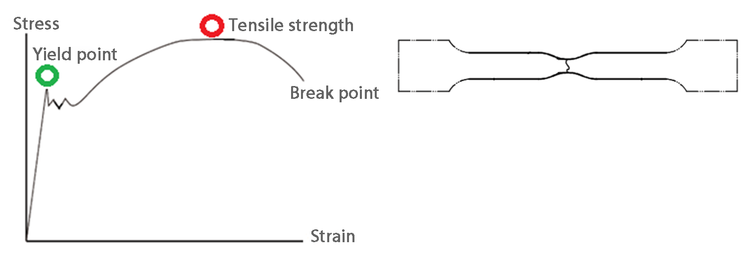
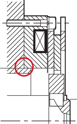
This is the stress corresponding to the maximum test force in the JIS standards (JIS Z2241 "Metal Material Tensile Test Method"). *The stress here is given as the value obtained by dividing the test force at any point in time during a test with the original cross-sectional area of the test specimen (the cross-sectional area before being pulled). In addition, it is the value obtained by dividing the maximum tensile load that can be withstood by a test specimen in a tensile test by the original cross-sectional rea of the parallel part of the test specimen in JIS G0202 "Iron and Steel Terms (Tests)." *The test conditions and test specimen dimensions are determined in the tensile test. This means that the test specimen has a shape like the figure (this is the one when broken). Consequently, although we tend to think of the tensile strength as the tensile load, it is stress not a load.
Iron and steel materials stretch little by little when pulled. However, they return to how they were before if there is no force pulling on them near the yield point in the diagram. This region is called the "elasticity region." However, if it is pulled beyond that, it become the "plasticity region." It will then become deformed and not return to how it was before. If pulled further, cracks will be produced and it will finally break.
"Stress - stain line diagrams" as shown in the figure represent the measurement results of a tensile test like this with the stress and strain (displayed as a percentage by dividing the elongation with the original length). There are some materials that do not show the yield point in the diagram on a line diagram. For example, there are no such line diagrams for cast iron that does not stretch easily or stainless steel which stretches well.
The maximum stress in the line diagram at the position with the red circle is the tensile strength in this "stress - strain line diagram." We determine what material to use to maintain the strength when developing and designing products. However, it is very important to know the tensile strength value at which the material will eventually break if a tensile load beyond that is applied as one of the mechanical properties of materials.
Thermal refining
-
Thermal refining refers to a treatment that combines quenching and tempering. Accordingly, "S45C thermal refining" is the quenching and tempering of S45C materials. It is possible to further harden materials with thermal refining. We use S45C thermal refined equivalent parts for the Mechanical Axis Lock / POSILOCK outer sleeves, outer rings, inner sleeves, inner rings, front tapering and rear tapering in the products of Miki Pulley.
-
"Quenching" refers to a treatment in which steel is heated red and then quickly cooled. The purpose of this is to harden the steel. Nevertheless, it is unstable like this. This means it is liable to becoming brittle and breaking. Therefore, we adjust the hardness by heating it again at a prescribed temperature. This is called "tempering." Accordingly, quenching and tempering are performed as one set.
There are also "S45C non-thermal refined materials". These are not thermal refined. However, they are not simply S45C materials, Non-thermal refining means it has a hardness at the same level as thermal refined materials even without performing thermal refining.
Tightening torque
-
⇒Please read the "torque wrench" term.
Torque
-
⇒Please also read the "service factor" term with related content.
-
This is the value obtained by multiplying the force that is attempting to rotate an object by the distance from the center of the object on which that force is acting. In other words, force × distance. The unit of this is [Nm]. However, the torque in couplings is not a value for rotating the coupling; rather, it is displayed as the value of the power that the coupling can transmit.
The coupling specification tables of Miki Pulley give this as the "allowable torque" or "normal torque" and "maximum torque." The allowable torque is the value at which there is no problem if it is used at that value or less. We give the "allowable torque" for comparatively rigid couplings (e.g., SERVOFLEX, SERVO RIGID and SCMIDT).
In addition, we give both the "normal torque" and "maximum torque" for HELI-CAL, BAUMANNFLEX, SPRFLEX and BELLOWFLEX. There will be no problem if used at or below the "normal torque." However, the torque applied to the coupling may increase due to shocks or vibrations on occasion. We consider such times to be the "maximum torque." This is torque for which there is no problem if it is applied to the coupling on a temporary basis. It is the value at which it is OK if it is applied a few times day. These torque values may be limited lower under conditions such as the coupling hole diameter and number of rotations used. The specifications differ depending on the coupling you use in this manner. Therefore, please thoroughly check your usage conditions and select an appropriate coupling.
Torque driver
-
⇒Please read the "torque wrench" term.
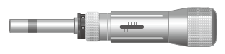
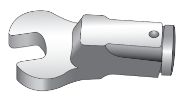
Torque wrench
-
⇒The "torque driver" term also has the same content.
-
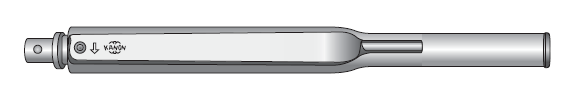
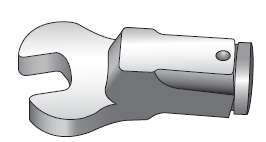
This refers to a tool to tighten bolts and screws. It is not possible to tighten with the tightening torque specified for the normal diameter of bolts and screws, such as the M8, by hand. This means a torque wrench is necessary.
The tightening torque is specified because it secures in place with a certain tension in the bolts and screws. Bolts can be secured in place without looseness by tension acting between the respective screw threads at the bolt and threaded screw holes. Accordingly, if the tightening torque is weak, the bolts will become loose while being used. If the bolts are loose, they may jump out from a rotating product. This means there is a danger of a serious accident.
Conversely, if the tightening torque is too high, the screw threads may become damaged. In that case, the tension acting between the screw threads may become weaker. This may eventually lead to the bolts becoming loose. Bolts will become loose sooner or later whether the tightening torque is too weak or too strong like this. Therefore, it is necessary to fix in place bolts and screws with the specified tightening torque. One of the causes of couplings becoming damaged is when the tightening torque of the bolts and screws and couplings is not managed.
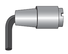
A torque wrench is effective when tightening hexagon socket head cap screws and hexagon head bolts with a comparatively large torque. There are also torque drivers in addition to torque wrenches. Torque drivers can be used like a Phillips head screwdriver. Therefore, it is an effective tool when the tightening torque is small like with hexagon socket head screws. Furthermore, an attachment called a "head" is used for each. Therefore, it is possible to use it properly to suit the shape of the bolt or screw.
Please refer to the SERVOFLEX catalog or ETP Bush catalog and POSILOCK catalog for torque wrenches or torque drives conforming to the product size.
(Static/dynamic)Torsional stiffness
-
This value indicates the hardness in the torsional direction of the coupling. It is expressed in terms of the torque required when twisting in the rotational direction and the deformed angle. The unit is "Nm/rad." The advantage of using a coupling with a high torsional stiffness is that it can transmit the force and movement from the input shift to the output shaft without change. For example, it dramatically reduces the printing misalignment in printing presses. This allows a high-precision finish to be obtained.
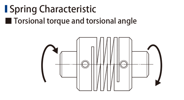
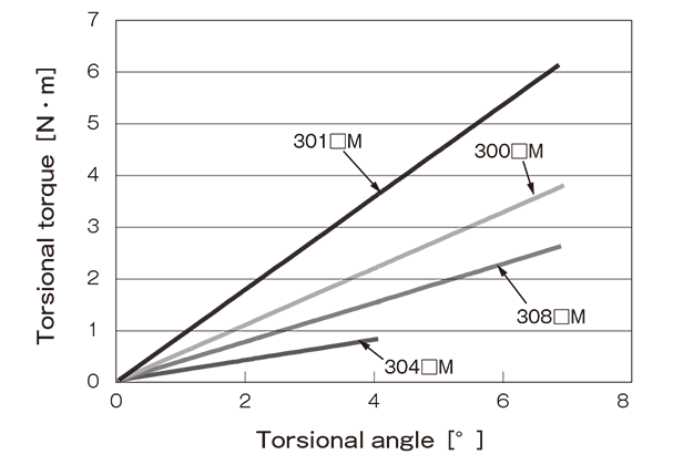
Next, let's compare the torsional stiffnesses. They can both be used for servo motors. Furthermore, with Φ44 couplings that have the same outer diameter, it is 20,000 Nm/rad for the SERVOFLEX Coupling / SFC-040SA2 and 996 Nm/rad for the STEPFLEX Coupling / STF-044SA1. This is a difference of approximately 20 times. This shows that the SERVOFLEX has high rigidity and excellent responsiveness. However, the strong point of STEPFLEX lies in its high attenuation performance and low counterforce. This means it is also possible to avoid resonance over a wide range of operating speeds in addition to allowing quick attenuation of vibrations. Miki Pulley handles a wide variety of couplings so you can select one to suit your purpose.
The "static torsional stiffness" (or "torsional stiffness" is given in the coupling specification tables of Miki Pulley. However, the "dynamic torsional stiffness" is described for the CF-A, CF-H and CM models of CENTAFLEX Couplings. The static torsional stiffness depends on the amount of bending with a force when a force is applied slowly while the dynamic torsional stiffness depends on the amount of bending with a force when a force is applied at a certain speed. Moreover, in general, the difference between the static and dynamic torsional stiffnesses is small for metals. However, the dynamic torsional stiffness tends to be higher than the static torsional stiffness in rubber and resin couplings. Therefore, we give the dynamic torsional stiffness as a value suitable for actual use.
Varistor
-
This refers to an electronic component which reduces the voltage flowing in the opposite direction that occurs when an electromagnetic coil is de-energized. Miki Pulley calls this a varistor or protective element.
The coils of electromagnetic clutches and electromagnetic brakes have the property of attempting to retain the current flowing through the coil. To that end, when de-energized, in other words, when the current loop is forcibly released, the energy stored in a coil becomes an excessive reverse direction voltage (reverse electromotive voltage). This reverse electromotive voltage has adverse effects. For example, it breaks the semiconductor elements of control circuits, degrades the insulation of coils, shortens the life of relays, produces the welding phenomenon, and leads to the current flowing through the wire becoming noise.
Accordingly, connecting a varistor in parallel with the coil allows the varistor to absorb the reverse electromotive voltage. However, it is necessary to also select a size of varistor according to the voltage applied to the coil - in other words, according to the model and size of the electromagnetic clutch and electromagnetic brake of Miki Pulley. The recommended electromagnetic clutch / electromagnetic brake power device (some types have a varistor already built into them) suitable for each model / size and a varistor list are given in our catalogs. Please use these to select an appropriate varistor.
Yield point
-
⇒Please also read the "strain" term.
⇒Please also read the "tensile strength" term.
-
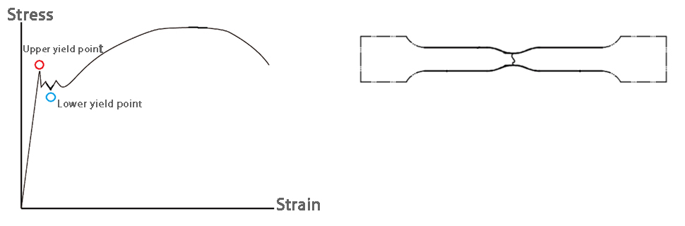
This is the value from which the maximum load prior to the start of the parallel part of a specimen yielding in the course of a tensile test of metallic materials is divided by the original cross-sectional area of the parallel part in JIS G0202 "Steel Terms (Tests)". The measurement results of the tensile test represented with stress and strain (display as a % with the elongation divided by the original length) becomes a "stress - strain line diagram" as in the figure. In this diagram, the rising straight line drops sharply and there are also some parts that are jagged. This is the part where the strain increases even though the stress here does not change that much. It is called the "yield area." The point with the greatest stress here is called the "upper yield point" while the point with the least stress here is called the "lower yield point." When it is not confusing, the upper yield point is called the "yield point." There are also some materials that do not show an upper yield point on a stress - strain line diagram. The point that indicates "0.2% stress" is called the yield point in such materials.
The "Design Check Items / Hub Minimum Outer Diameter List" is given in the catalog for the ETP Bushes of the Friction Fasteners in the products of Miki Pulley. The minimum outer diameter dimensions of the hub aligned to the size of the ETP Bush is expressed according to the material of the hub used by the customer in this list. This is the hub outer diameter dimensions obtained from the yield point (point indicating 0.2% stress resistance) of the hub material selected here. The "0.2" in the item of the list is this value. The point indicating 0.2% stress resistance here can also be called the point where permanent strain of 0.2% occurs.
When fixing in place hubs to the bodies of ETP Bushes, the sleeve on the hub side of the body expands. The reason "Hub Minimum Outer Diameter List" is published in the catalog is that the hub deforms or breaks if the outer dimensions of the hub used at this time are smaller than the value in the list. The yield point like this is an important value in the selection of materials in the same way as the tensile strength.
⇒"Friction Fastener ETP-E Operating Principles" video
⇒"Friction Fastener ETP-A Operating Principles" video