日本語
日本語 English
 Deutsch
 中文
中文 한국어
한국어


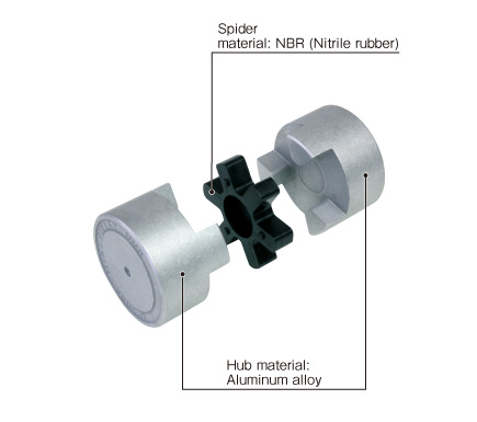
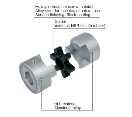
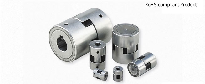
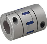
AL Models

![]()
AL Models
[Specifications]
| Model | Torque | Misalignment | Max. rotation speed [min-1] | Moment of inertia [kg・m2] | Mass [kg] | |||
|---|---|---|---|---|---|---|---|---|
| Nominal [N・m] | Max. [N・m] | Parallel [mm] | Angular [°] | Axial [mm] | ||||
| AL-035 | 0.5 | 1.5 | 0.1 | 0.5 | +0.3 | 18000 | 0.38×10⁻⁶ | 0.01 |
| AL-050 | 1.5 | 4.5 | 0.2 | 1.0 | ±0.5 | 12000 | 5.10×10⁻⁶ | 0.06 |
| AL-070 | 3 | 9 | 0.2 | 1.0 | ±0.5 | 9000 | 1.79×10⁻⁵ | 0.12 |
| AL-075 | 5 | 15 | 0.2 | 1.0 | ±0.5 | 7000 | 5.36×10⁻⁵ | 0.21 |
| AL-090 | 8 | 24 | 0.3 | 1.0 | ±0.5 | 6000 | 1.15×10⁻⁴ | 0.31 |
| AL-095 | 10 | 30 | 0.3 | 1.0 | ±0.5 | 6000 | 1.40×10⁻⁴ | 0.36 |
| AL-100 | 25 | 75 | 0.3 | 1.0 | ±0.7 | 5000 | 4.34×10⁻⁴ | 0.78 |
| AL-110 | 50 | 150 | 0.3 | 1.0 | ±0.7 | 4000 | 1.43×10⁻³ | 1.56 |
*Max. rotation speed does not take into account dynamic balance or mounting misalignment.
*The moment of inertia and mass are measured for the pilot bore.
[Dimensions]
couplings

| Model | d1, d2 | D | L | L1 | L2 | ||
|---|---|---|---|---|---|---|---|
| Pilot bore | Min. | Max. | |||||
| AL-035 | 4 | 4 | 8 | 16.1 | 20.5 | 6.5 | 7.5*1 |
| AL-050 | 5 | 6 | 16 | 27 | 43.2 | 15.5 | 12.2 |
| AL-070 | 5 | 6 | 20 | 35 | 49.2 | 18.5 | 12.2 |
| AL-075 | 5 | 7 | 26 | 45 | 54.4 | 21.0 | 12.4 |
| AL-090 | 5 | 9 | 28 | 54 | 55.0 | 21.0 | 13.0 |
| AL-095 | 5 | 9 | 28 | 55 | 61.0 | 24.0 | 13.0 |
| AL-100 | 5 | 11 | 36 | 66 | 88.0 | 35.0 | 18.0 |
| AL-110 | 8 | 11 | 48 | 85 | 110.0 | 44.0 | 22.0 |
*"Pilot bore" refers to center processing. Minimums and maximums for d1 and d2 are values at the MIKI PULLEY standard hole-drilling standards.
*The value marked *1 leaves a 1 mm space for the thickness of the spider body.
[Dimensions]
Spider

| Coupling Model | Spider Model | L2 | R | K |
|---|---|---|---|---|
| AL-035 | L-035 | 6.5 | ― | ― |
| AL-050 | L-050 | 12.2 | ― | ― |
| AL-070 | L-070 | 12.2 | ― | ― |
| AL-075 | L-075 | 12.4 | 20 | 6.0 |
| AL-090 | L-090/095 | 13.0 | 22 | 6.3 |
| AL-095 | L-090/095 | 13.0 | 22 | 6.3 |
| AL-100 | L-100 | 18.0 | 26 | 6.0 |
| AL-110 | L-110 | 22.0 | 30 | 6.0 |
[Standard Hole-drilling Standards]
| Models compliant with the old JIS standard (class 2) JIS B 1301 1959 | Models compliant with the new JIS standard (H9) JIS B 1301 1996 | Models compliant with the new JIS standard (JS9) JIS B 1301 1996 | Models compliant with the motor standard JIS C 4210 2001 | ||||||||||||||||
|---|---|---|---|---|---|---|---|---|---|---|---|---|---|---|---|---|---|---|---|
| Nominal bore diameter | Bore diameter (d1, d2) | Keyway width (W1, W2) | Keyway height (T1, T2) | Set screw hole (M) | Nominal bore diameter | Bore diameter (d1, d2) | Keyway width (W1, W2) | Keyway height (T1, T2) | Set screw hole (M) | Nominal bore diameter | Bore diameter (d1, d2) | Keyway width (W1, W2) | Keyway height (T1, T2) | Set screw hole (M) | Nominal bore diameter | Bore diameter (d1, d2) | Keyway width (W1, W2) | Keyway height (T1, T2) | Set screw hole (M) |
| Tolerance H7, H8 | Tolerance E9 | - | Tolerance H7 | Tolerance H9 | - | Tolerance H7 | Tolerance JS9 | - | Tolerance G7, F7 | Tolerance H9 | - | ||||||||
| 6 | 6+0.0180 | - | - | 2-M4 | - | - | - | - | - | - | - | - | - | - | - | - | - | - | - |
| 7 | 7+0.0220 | - | - | 2-M4 | - | - | - | - | - | - | - | - | - | - | - | - | - | - | - |
| 8 | 8+0.0220 | - | - | 2-M4 | - | - | - | - | - | - | - | - | - | - | - | - | - | - | - |
| 9 | 9+0.0220 | - | - | 2-M4 | - | - | - | - | - | - | - | - | - | - | - | - | - | - | - |
| 10 | 10+0.0220 | - | - | 2-M4 | - | - | - | - | - | - | - | - | - | - | - | - | - | - | - |
| 11 | 11+0.0180 | - | - | 2-M4 | - | - | - | - | - | - | - | - | - | - | - | - | - | - | - |
| 12 | 12+0.0180 | 4+0.050+0.020 | 13.5+0.30 | 2-M4 | 12H | 12+0.0180 | 4+0.0300 | 13.8+0.30 | 2-M4 | 12J | 12+0.0180 | 4±0.0150 | 13.8+0.30 | 2-M4 | - | - | - | - | - |
| 14 | 14+0.0180 | 5+0.050+0.020 | 16.0+0.30 | 2-M4 | 14H | 14+0.0180 | 5+0.0300 | 16.3+0.30 | 2-M4 | 14J | 14+0.0180 | 5±0.0150 | 16.3+0.30 | 2-M4 | 14N | 14+0.024+0.006 | 5+0.0300 | 16.3+0.30 | 2-M4 |
| 15 | 15+0.0180 | 5+0.050+0.020 | 17.0+0.30 | 2-M4 | 15H | 15+0.0180 | 5+0.0300 | 17.3+0.30 | 2-M4 | 15J | 15+0.0180 | 5±0.0150 | 17.3+0.30 | 2-M4 | - | - | - | - | - |
| 16 | 16+0.0180 | 5+0.050+0.020 | 18.0+0.30 | 2-M4 | 16H | 16+0.0180 | 5+0.0300 | 18.3+0.30 | 2-M4 | 16J | 16+0.0180 | 5±0.0150 | 18.3+0.30 | 2-M4 | - | - | - | - | - |
| 17 | 17+0.0180 | 5+0.050+0.020 | 19.0+0.30 | 2-M4 | 17H | 17+0.0180 | 5+0.0300 | 19.3+0.30 | 2-M4 | 17J | 17+0.0180 | 5±0.0150 | 19.3+0.30 | 2-M4 | - | - | - | - | - |
| 18 | 18+0.0180 | 5+0.050+0.020 | 20.0+0.30 | 2-M4 | 18H | 18+0.0180 | 6+0.0300 | 20.8+0.30 | 2-M5 | 18J | 18+0.0180 | 6±0.0150 | 20.8+0.30 | 2-M5 | - | - | - | - | - |
| 19 | 19+0.0210 | 5+0.050+0.020 | 21.0+0.30 | 2-M4 | 19H | 19+0.0210 | 6+0.0300 | 21.8+0.30 | 2-M5 | 19J | 19+0.0210 | 6±0.0150 | 21.8+0.30 | 2-M5 | 19N | 19+0.028+0.007 | 6+0.0300 | 21.8+0.30 | 2-M5 |
| 20 | 20+0.0210 | 5+0.050+0.020 | 22.0+0.30 | 2-M4 | 20H | 20+0.0210 | 6+0.0300 | 22.8+0.30 | 2-M5 | 20J | 20+0.0210 | 6±0.0150 | 22.8+0.30 | 2-M5 | - | - | - | - | - |
| 22 | 22+0.0210 | 7+0.061+0.025 | 25.0+0.30 | 2-M6 | 22H | 22+0.0210 | 6+0.0300 | 24.8+0.30 | 2-M5 | 22J | 22+0.0210 | 6±0.0150 | 24.8+0.30 | 2-M5 | - | - | - | - | - |
| 24 | 24+0.0210 | 7+0.061+0.025 | 27.0+0.30 | 2-M6 | 24H | 24+0.0210 | 8+0.0360 | 27.3+0.30 | 2-M6 | 24J | 24+0.0210 | 8±0.0180 | 27.3+0.30 | 2-M6 | 24N | 24+0.028+0.007 | 8+0.0360 | 27.3+0.30 | 2-M6 |
| 25 | 25+0.0210 | 7+0.061+0.025 | 28.0+0.30 | 2-M6 | 25H | 25+0.0210 | 8+0.0360 | 28.3+0.30 | 2-M6 | 25J | 25+0.0210 | 8±0.0180 | 28.3+0.30 | 2-M6 | - | - | - | - | - |
| 28 | 28+0.0210 | 7+0.061+0.025 | 31.0+0.30 | 2-M6 | 28H | 28+0.0210 | 8+0.0360 | 31.3+0.30 | 2-M6 | 28J | 28+0.0210 | 8±0.0180 | 31.3+0.30 | 2-M6 | 28N | 28+0.028+0.007 | 8+0.0360 | 31.3+0.30 | 2-M6 |
| 30 | 30+0.0210 | 7+0.061+0.025 | 33.0+0.30 | 2-M6 | 30H | 30+0.0210 | 8+0.0360 | 33.3+0.30 | 2-M6 | 30J | 30+0.0210 | 8±0.0180 | 33.3+0.30 | 2-M6 | - | - | - | - | - |
| 32 | 32+0.0250 | 10+0.061+0.025 | 35.5+0.30 | 2-M8 | 32H | 32+0.0250 | 10+0.0360 | 35.3+0.30 | 2-M8 | 32J | 32+0.0250 | 10±0.0180 | 35.3+0.30 | 2-M8 | - | - | - | - | - |
| 35 | 35+0.0250 | 10+0.061+0.025 | 38.5+0.30 | 2-M8 | 35H | 35+0.0250 | 10+0.0360 | 38.3+0.30 | 2-M8 | 35J | 35+0.0250 | 10±0.0180 | 38.3+0.30 | 2-M8 | - | - | - | - | - |
| 38 | 38+0.0250 | 10+0.061+0.025 | 41.5+0.30 | 2-M8 | 38H | 38+0.0250 | 10+0.0360 | 41.3+0.30 | 2-M8 | 38J | 38+0.0250 | 10±0.0180 | 41.3+0.30 | 2-M8 | 38N | 38+0.050+0.025 | 10+0.0360 | 41.3+0.30 | 2-M8 |
| 40 | 40+0.0250 | 10+0.061+0.025 | 43.5+0.30 | 2-M8 | 40H | 40+0.0250 | 12+0.0430 | 43.3+0.30 | 2-M8 | 40J | 40+0.0250 | 12±0.0215 | 43.3+0.30 | 2-M8 | - | - | - | - | - |
| 42 | 42+0.0250 | 12+0.075+0.032 | 45.5+0.30 | 2-M8 | 42H | 42+0.0250 | 12+0.0430 | 45.3+0.30 | 2-M8 | 42J | 42+0.0250 | 12±0.0215 | 45.3+0.30 | 2-M8 | 42N | 42+0.050+0.025 | 12+0.0430 | 45.3+0.30 | 2-M8 |
| 45 | 45+0.0250 | 12+0.075+0.032 | 48.5+0.30 | 2-M8 | 45H | 45+0.0250 | 14+0.0430 | 48.8+0.30 | 2-M10 | 45J | 45+0.0250 | 14±0.0215 | 48.8+0.30 | 2-M10 | - | - | - | - | - |
| 48 | 48+0.0250 | 12+0.075+0.032 | 51.5+0.30 | 2-M8 | 48H | 48+0.0250 | 14+0.0430 | 51.8+0.30 | 2-M10 | 48J | 48+0.0250 | 14±0.0215 | 51.8+0.30 | 2-M10 | 48N | 48+0.050+0.025 | 14+0.0430 | 51.8+0.30 | 2-M10 |
*All standards starting from ø11 are the same as those in the old JIS standards column.
*For AL-035, tolerance is +0.05+0 regardless of the bore diameter, and set screw size is M3.
*Positions of set screws and keyways are not on the same plane.
*Set screws are included with the product.
*Positioning precision for keyway milling is determined by sight.
*Contact Miki Pulley when the keyway requires a positioning precision for a particular flange hub.
*Consult the technical documentation at the end of this volume for standard dimensions for bore drilling other than those given here.
[Set screw position]
| Model | Distance C from edge[mm] |
|---|---|
| AL-035 | 3.5 |
| AL-050 | 7.5 |
| AL-070 | 9 |
| AL-075 | 10 |
| AL-090 | 12 |
| AL-095 | 12 |
| AL-100 | 12 |
| AL-110 | 15 |
![]()
![]()
![]()
![]()
![]()
![]()