日本語
日本語 English
 Deutsch
 中文
中文 한국어
한국어


Coupling Q&As
Solve all your questions about couplings!
We have posted technical terms and frequently asked technical questions about coupling here.
Please click here for other frequently asked questions.
If you cannot find your question, please contact us using the “Inquiries Form.”
Index
- Q. Please tell me about the types of couplings.
- Q. Please tell me about mounting errors .
- Q. What is resonance?
- Q. Please tell me about the torsion spring constant.
- Q. Please tell me about the moment of inertia.
- Q. What is the normal torque, maximum torque and allowable torque?
- Q. Please tell me about balance.
- Q. Please tell me about the operating temperature of couplings.
- Q. Does the transmission efficiency of couplings decline due to mounting errors?
- Q. What is the change in the angular velocity of the couplings?
- Q. What should I do to suppress changes in the angular velocity?
- Q. Are there any couplings with high electrical insulation?
- Q. Are there couplings that can be used in a clean room?
- Q. What is the difference between the minimum hole diameter and the pilot hole?
- Q. How is the maximum rotational speed determined?
- Q. What is torque?
- Q. What happens if I don’t tighten the bolts at the specified tightening torque?
- Q. What happens if I use a product beyond the specifications in the catalog?
- Q. What methods are there for fastening couplings and axes?
- Q. What is the difference between backlash and torsional delay?
- Q. What are the key processing tolerances?
- Q. What happens if used at greater than the maximum mounting error
of the coupling?
- Please tell me about the types of couplings.
-
Couplings that connect axes to transmit power are classified by the relative position of the two axes, the method of absorbing mounting errors (eccentricity, declination and axial displacement), whether or not they have a deflection and their type.
Fixed couplings: These do not allow for mounting errors, but they are inexpensive. These are designed for a large reaction force and low speed rotation.
Deflection couplings: These can absorb mounting errors between axis centers.
There are also gears, chains, metal springs and rubber among deflection couplings. We mainly handle flexible axis couplers.
In addition, it is necessary to change the type depending on the application. For example, if the drive is an engine, rubber or plastic couplings with good vibration absorption are used. Meanwhile, couplings made of torsion rigid metal are used in precision machines (e.g., servo motors).
→ Please see “Types and Features of Couplings”
for the more details of the types of couplings.
- Please tell me about mounting errors (misalignment).
-
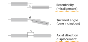
Coupling mounting errors are divided into three.
(1)Eccentricity: This is the state in which the center line between the axes is misaligned because the center of the axes is not aligned.
(2)Declination: This is the state in which the center line between the axes is misaligned at a certain angle (bent).
(3)Axial displacement: This is the state in which the center line between the axes moves in the axial direction even though it is aligned.
- What is resonance?
-
If vibrations are applied to the characteristic frequency possessed by each thing at the same frequency as that characteristic frequency from outside, that thing will vibrate even more than the applied vibrations.
This phenomenon is called resonance.
In other words, it occurs when the characteristic frequency and the excitation frequency match. In the case of coupling resonance, vibrations occur in the direction of rotation. Therefore, it is called resonance due to torsion vibrations. (Motors have little rotation unevenness and generate few torsion vibrations. Therefore, the resonance phenomenon is not such a problem. In the case of a stepping motor, the resonance phenomenon occurs occasionally.)
The characteristic frequency is the inherent frequency possessed by that thing. The frequency does not change. However, the excitation frequency changes in proportion to the engine rotation.
Accordingly, resonance occurs when the characteristic frequency and the excitation frequency overlap at a certain rotational speed. Consequently, it is also important to know the characteristic frequency of that thing. We have included a simple calculation formula to find the characteristic frequency in the catalogs for our engine couplings.
Incidentally, the characteristic frequency of humans is said to be 2 to 3 Hz.
The vibrating amplitude (the degree of shaking) is amplified in the resonance state, while it becomes larger to an unthinkable degree normally.
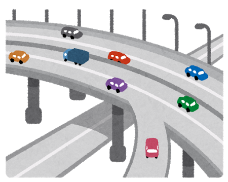
When driving on a highway in a car with unbalanced tires, the vibrations will increase at a certain speed. However, have you ever experienced a reduction in vibrations if you go greater than that speed? The point when the vibrations increase is the resonance point. The speed at that time is the resonance speed. This is resonance rotation.
- Please tell me about the torsion spring constant.
-
First, let’s consider the spring constant using a coil spring. When a coil spring is hung from a ceiling, the state in which it hangs down naturally with no weight applied is A:m. When the load (weight) in W:N is affixed and hung here, the coil spring becomes Bm.
First, let’s consider the spring constant using a coil spring. When a coil spring is hung from a ceiling, the state in which it hangs down naturally with no weight applied is A:m. When the load (weight) in W:N is affixed and hung here, the coil spring becomes Bm.
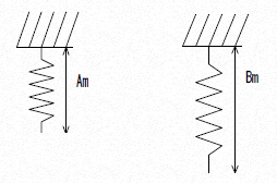
Spring constant = W N÷(B:m-A:m)
The torsion spring constant is one for which an article that has previously been considered to be in a straight line is replaced in the direction of rotation. The relationship between the force and twist angle when a certain article is twisted in the direction of rotation at a certain force is called the torsion spring constant.
For example, when torque of C Nm is applied to a certain coupling, the torsion spring constant at the time the coupling is twisted at the D deg in response to that force is expressed as below.
Torsion spring constant = C Nm / D deg
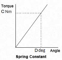
The unit is Nm/deg. We have included several types of torsion spring constant unit in our catalogs. In general, we have used Nm/rad as the unit of the torsion spring constant. The rad (radian) is a unit that expresses the angle: 1rad=180/π deg = 57.3deg.
In general, couplings that are soft in the direction of rotation (e.g., rubber couplings) have a low torsion spring constant, while couplings that are hard in the direction of rotation (e.g., metal plate spring couplings) have a higher torsion spring constant.
- Please tell me about the moment of inertia.
-
Consider a ping-pong ball and an iron ball the same size as that ping-pong ball being rolled to a certain speed, for example. The ping-pong ball will start to roll with a light force. However, a force greater than that for the ping-pong ball is required to roll the iron ball. Conversely, the iron ball requires considerably more time and distance until it comes to a stop naturally when the ping-pong ball and iron ball are being rolled at a certain speed. It also requires more power to forcibly stop the iron ball from rolling.
In this way, the ease of movement when rolling an object to a certain speed and how much force remains when trying to stop that object from a certain speed is called inertia.
The moment of inertia is the inertia that occurs when an object is rotated. It is an important unit to understand the ease of rotation, the ease of stopping and how to apply force during rotation.The formula for the moment of inertia varies depending on what kind of shape is rotating from the center of the rotating body.
The unit is expressed as Kg・m2
Why do we need to know the moment of inertia? For example, the positioning accuracy for our SFS (metal leaf spring couplings) increases with use in servo motors. However, if the moment of inertia becomes larger, the movement and response when starting up and stopping may become poor. This may affect the positioning accuracy.
→ Please see “Moment of Inertia J Formula List”
for the moment of inertia formulas.
→ Please see the “Moment of Inertia J Simplified Chart”
if you wish to learn about the moment of inertia.
- What is the normal torque, maximum torque and allowable torque?
- We have two ways of calculating this. In one, we determine the standard torque (normal torque), set approximately twice that as the maximum torque and then base the allowable torque under the assumption of use at the maximum torque about a few dozen times a day.
In the other, we determine the maximum torque that can be allowed like with a metal leaf spring coupling and then base the allowable torque under the assumption of use at a torque below that.
These differences are used depending on the structure and type of coupling. In general, we have adopted the indication for the allowable torque with metal leaf spring couplings.
Metal leaf springs are often coupled with servo motors. Servo motors produce a maximum torque more than approximately three times that of the normal torque.
In addition, they startup and stop at a high frequency. Therefore, there are no couplings that can allow these maximum torques.
Accordingly, it is best to make a selection according to the allowable torque of the coupling.
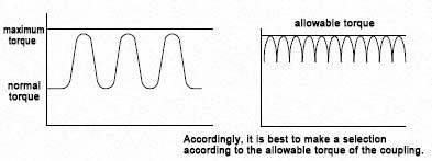
On the other hand, general-purpose motors and engines are generally used at their normal torque. The maximum torque is applied when starting up and stopping about a few dozen times a day. If we express the coupling transmission torque under the premise of such usage, it will be displayed as the normal torque and the maximum torque.
In any case, it is not possible to use beyond the maximum torque and allowable torque of the coupling.
- Please tell me about balance.
- Balance is stipulated as “good equilibrium” by the JIS.
(→ Click here for detailed materials on good equilibrium)
(1) The equilibrium of rotating objects is a mass distribution imbalance that arises when a rotating object (e.g., a coupling) rotates. For example, if you affix a weight to the edge of a spinning top and turn it, the imbalance of the mass of that weight will arise in the spinning top. Conversely, the imbalance of that mass is called the unbalanced amount. This is ultimately expressed as mass.
(2)If the unbalanced amount is large, we generally say that the balance is poor. However, when rotating in such a state, vibrations will occur. In addition, the magnitude of these vibrations also differs depending on the magnitude of the unbalanced amount and differences in the rotational speed. The vibrations increase if the rotational speed increases when the unbalanced amount is large. Conversely, if the unbalanced amount becomes smaller and the rotational speed lower, the vibrations decrease.
(3)Correcting and reducing the unbalanced amount possessed by a rotating object is called balancing; it is also called balancing in the JIS. Balancing consists of one-side balancing in which the unbalanced amount of a rotating object is adjusted in one place and two-sided balancing in which it is adjusted in two places.
(4)The balancing standard is expressed as G□□ by the JIS and is called the good equilibrium grade. For example, there is a range to the numerical values after G with G6.3, G100 and G4000. These numerical values indicate the grade. The smaller the numerical value, the greater the equilibrium – the grade of the good equilibrium is high. The higher the grade, the more it is used in the rotating body of precision machines. The balance of the couplings handled by our firm is at a grade of G2.5 to G16.
(5) Balancing is performed while removing the mass of the unbalanced amount. The mass of the unbalanced amount that matches the grade of the good equilibrium is obtained with a calculation. If the grade of the good equilibrium is high, the mass of the removed unbalanced amount becomes small, so it takes time to balance.
In addition, if a coupling adjusted with a balancer is removed, re-mounted and then measured, the unbalanced amount may vary. It also depends on the coupling mounting and the centering precision. This is called balance reproducibility.

- Please tell me about the operating temperature of couplings.
- The operating temperature range varies depending on the materials and specifications of the coupling. For example, the natural rubber used in our rubber couplings vitrifies at a low temperature of -40°C while the surfaces hardens and creasing and cracks are liable to arise at a high temperature of 120°C. Therefore, we have set the operating temperature range of our rubber couplings to between -30°C and 95°C.
Similarly, couplings made with aluminum or stainless steel may thermally expand under high temperatures. Accordingly, we have set the maximum operating temperature to 120°C with consideration for safety.
It is also possible to use outside this operating temperature range depending on the conditions, but it may not be able to satisfy its original specifications (e.g., its life may be shortened).
→Please download the catalog from each product page or
request a catalog from “Free Catalog Request” for the detailed operating
temperatures of each coupling.
- Does the transmission efficiency of couplings decline due to mounting errors?
- Yes.
In the case of elastic couplings, such a mounting error is absorbed by deformation of the deflection material (rubber, plastic and metal).
Nevertheless, a reaction force is generated on the bearings due to the deformation of the deflection material. In other words, the power generated from the motor is consumed somewhat by the reaction force on the bearings due to the coupling part.Accordingly, the power will be lost somewhat, so the transmission efficiency will decline.
As described above, considering the transmission efficiency, the smaller the mounting error, the better the transmission efficiency. Furthermore, the smaller the reaction force on the bearings due to mounting errors, the better the transmission efficiency.
- What is the change in the angular velocity of the couplings?
- The change in the angular velocity refers to the subtle rotation irregularity of the rotational speed on the output side that arises due to the use of the coupling as an intermediary even though the drive side turns at a uniform rotation (constant rotation). In general, if there is a mounting error to a certain extent with couplings, a change in the angular velocity is produced on the transmission side to a greater or lesser extent. However, a change in the rate of the angular velocity of about 1% is not really a problem with an angle of deviation of 1° or less.
(This is different for special devices requiring a uniform velocity.)
- What should I do to suppress changes in the angular velocity?
- You can suppress changes in the angular velocity by ensuring that the amount of concentricity and the angle of deviation is close to zero.
In particular, the double element model of servo flex couplings is perfect for angle detector applications because it has few changes in the angular velocity for mounting errors.
If uniform velocity is required with large mounting errors, we recommend a uniform velocity joint.
- Are there any couplings with high electrical insulation?
- In general, rubber and resin couplings have an insulating effect.
Nevertheless, there is a level to this insulation; it cannot be said to be easy insulated.
There are also rubber and resin couplings with low insulation depending on the material and shape, so confirmation is required.
For example, the insulation of our CF-X (resin couplings) is ∞Ω. However, this is 0.04 to 0.3×10^6Ω for our CF-A (rubber couplings). In general, it is said that there is insulation at 10^14Ω.
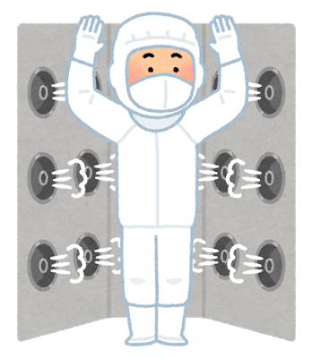
- Are there couplings that can be used in a clean room?
- Basically, the condition for use as a clean room should be that there are no powders or oil resulting from the friction of materials and no rust.
However, a level of some fine powder may be allowed depending on the conditions of the clean room.
Conduction-related equipment such as couplings is an assembly of parts. Consequently, there are always parts that are scraped due to friction and parts which suffer stress from friction.
Rust and corrosion are less liable to arise on the surface with aluminum and stainless-steel materials. However, parts not subject to surface treatment with a material using ordinary iron generate rust. Fine material wear powder and rust powder are always generated from such places.
Although there is a difference in the level, assuming that it is in the same state as the other machines used in the clean room, we recommend couplings made of stainless-steel or subjected to special surface treatment.
Please contact us for more details.
- What is the difference between the minimum hole diameter and the pilot hole?
- The minimum hole diameter refers to the hole diameter that has been subjected to finish processing. Therefore, it is the minimum value of the hole that can be used as it is. In addition, the pilot hole has a hole diameter subjected to centering and drilling as the preliminary step to finishing the hole. It is easy to process to finish the hole diameter, so generally, a pilot hole is established.
- How is the maximum rotational speed determined?
- One way is that this is determined by the material strength. We obtain the allowable circumferential speed with the material strength of the weakest part of the coupling. We then determine the maximum rotational speed with the dimeter of the coupling material and the allowable circumferential speed.
There is also the problem of balance. In general, the maximum rotation does not take into account balance. Accordingly, if used at high speed, it is necessary to separately consider the problem of balance. We also set the maximum rotational speed according to those limits.
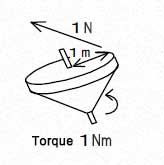
- What is torque?
- This is expressed as a moment in physics. Torque is the force that attempts to turn a certain rotating object. It is expressed as the product (multiplication) of the force and the distance from the center of the rotation. The torque when attempting to turn a spinning top with a radius of 1 m at a force of 1 N in the outer circumference tangential line direction of the spinning top is “1 m × 1 N = 1 Nm.”
- What happens if I don’t tighten the bolts at the specified tightening torque?
- If the tightening torque of the bolt does not satisfy the specified torque, the bolt will not be able to demonstrate its original functions. In addition, there are also concerns about loose bolts.
Conversely, if you tighten the bolt too strongly greater than the specified torque, too much stress will be placed on the bolt. This will lead to it becoming damaged. Alternatively, the material of the bolt seat may buckle and the axial force will decrease leading to the bolt becoming damaged.
As described above, if the bolt is not tightened at the specified tightening torque, it may not be possible to demonstrate the legitimate performance of the coupling. In the worst case, the product may become damaged.
- What happens if I use a product beyond the specifications in the catalog?
- This may lead to excessive mounting errors, excessive torque, excessive torque fluctuations and use outside the operating atmospheric temperature range. It may not be possible to demonstrate the legitimate functions as a coupling under such conditions.
Usually, the life of the coupling will be shortened. In the worst case, the product may become damaged.
- What methods are there for fastening couplings and axes?
- There are the following methods to fasten couplings and axes.
Type Photograph Features Key fastening: 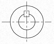
This is fastening with a key. We establish keyways on the coupling hole and axis respectively. Torque is then transmitted by inserting a key. At this time, tightening it with a set screw causes the axis to be pressed against the side of the coupling hole.
This increases the torque transmission efficiency.
There is a gap between the key groove and key and between the hole and axis with key fastening. Rattling may occur between these gaps depending on the load. This may become backlash.
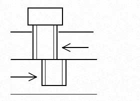
Fastening with a set screw: 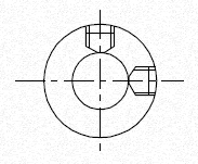
This is a method of fastening the hole just by tightening a set screw without establishing a key. The axial force of the set screw affects the magnitude of the transmission torque. In general, torque cannot be obtained with set screw fastening. This means we design it to gain transmission torque by flattening the axis. This is used for couplings with a small torque or small hole diameter (maximum of about Φ20). Fastening with a single clamp: 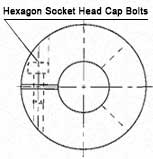
・This applies to forward and reverse servo
applications.
・Mounting is easy. The axis diameter is often
35 mm or less.Fastening with a double clamp: 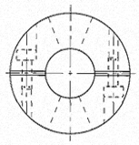
・The axis holding force is greater than that of
a single clamp.
・The axis is easily centered and fine adjustment is
possible (integrated type) with high precision.
・The axis diameter is up to about 40 mm.
Wedge fastening (taper fastening): 
・The axis holding force is greater than that of the
double clamp.
・A large number of clamping bolts and space in
the axial direction is required.
・It supports high speeds of over 20,000 rpm.
- What is the difference between backlash and torsional delay?
- Backlash is the mechanical rattling possessed by couplings. When mechanical parts are combined, rattling may arise in the fitting of the key and shaft and in the direction of rotation from the gaps between parts. This is called backlash. For example, this is the part that does not transmit torque within a certain angle range when switching from forward rotation to reverse rotation. Backlash is inappropriate for the couplings used in servo motors that require rotation and positioning precision.
Torsional delay is different strictly speaking from backlash. Torsional delay is particularly noticeable in soft couplings with torsional rigidity. For example, rubber is compressed in the direction of rotation in rubber couplings until reaching a state in which torque can be transmitted from after torque is applied. The drive side starts to rotate and the rubber then compresses until it reaches a state in which torque can be transmitted. The driven side then starts to rotate for the first time. The delay in transitioning to the state in which the driven side starts to rotate in response to the load from the initial state in which the drive side has started to rotate is called the torsional delay.
Regardless of whether backlash or torsional delay, it cannot be used when positioning accuracy is required of couplings. Nevertheless, conversely, torsional delay absorbs fluctuating torque and vibrations during rotation due to those characteristics. Therefore, it is employed in couplings used in engines with no relation to positional accuracy.
- What are the key processing tolerances?
-
JThis is defined as the fitting of the hole and axis and the key and keyway in the JIS standard.
(→ Fitting Tolerance Table)
The fitting is the relationship that results from the difference in the dimensions before the hole and axis are combined. There are grades to the fittings. These are represented by affixing numerical figures that indicate the grade to the symbol IT. The gap between the fitting is determined by this grade. Broadly divided, fittings consist of clearance fittings and tight fittings. It is necessary to press fit or strike when assembling with intermediate fittings and tight fittings. Therefore, we ask that you use tight fittings with Miki Pulley’s couplings.
In the case of the parallel key that we usually use, we define the key dimensions under the current JIS (new JIS) standards and then define the keyway dimensions by dividing them into two types with respect to that. This tolerance is P9 (premium grade) and Js9 (normal grade).
However, we process at the H9 grade for Miki Pulley’s standard hole processing standards. The key and keyway for both the P9 grade and Js9 grade are tight fitting and intermediate fitting, so we do not recommend this. This is because the H9 grade is tight fitting with easy assembly and no performance problems. The key standards were changed in 1976 for the JIS standards. The standards before that are called the old JIS standards and the standards after that are called the new JIS standards to distinguish them. There are type 1 and type 2 old JIS standards. We have adopted the type 2 standards with a large tolerance for Miki Pulley’s standard hole processing standards. This keyway width is grade E9. This is tight fitting, so there are no problems in use.
Moreover, new standard motor compatible standards have been prescribed in addition to the new JIS and old JIS. This is because the key dimensions of motors produced under the new standards differ slightly to the JIS standards. They keyway widths, tolerances and similar differ with respect to the hole diameter in the new JIS, old JIS and new standard motor compatible standards. Therefore, it is necessary to check to avoid confusion.
→ Miki Pulley’s Coupling Standard Hold Processing Standards
- What happens if used at greater than the maximum mounting error of the coupling?
- The results vary depending on the type of coupling and the element. Nevertheless, in general, we look at the safety factor. Therefore, although it depends on the size of the mounting error, it will not be damaged immediately. However, its life will be shortened and the component parts may become damaged and scatter due to the rotating objects. This means that this is extremely dangerous. Consequently, it cannot be used beyond the maximum mounting error.