 日本語
日本語 English
 Deutsch
 中文
中文 한국어
한국어


Hexagon Socket Head Cap Bolts (Excerpt from JIS B 1176 2014)
Last updated:18 June 2019

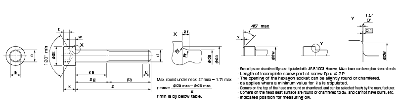
・The opening of the hexagon socket can be slightly round or chamfered.
・Screw tips are chamfered tips as stipulated with JIS B 1003. However, M4 or lower can have plain-sheared ends.
・Corners on the top of the head are round or chamfered, and can be selected freely by the manufacturer.
・Corners on the head seat surface are round or chamfered to dw, and cannot have burrs, etc.
Unit [mm]
| d | Nominal screw diameter | M1.6 | M2 | M2.5 | M3 | M4 | M5 | M6 | M8 | M10 | M12 | (M14) | M16 | M20 |
|---|---|---|---|---|---|---|---|---|---|---|---|---|---|---|
| p | 0.35 | 0.4 | 0.45 | 0.5 | 0.7 | 0.8 | 1 | 1.25 | 1.5 | 1.75 | 2 | 2 | 2.5 | |
| b | Reference | 15 | 16 | 17 | 18 | 20 | 22 | 24 | 28 | 32 | 36 | 40 | 44 | 52 |
| dk | Max. c) | 3.00 | 3.80 | 4.50 | 5.50 | 7.00 | 8.50 | 10.00 | 13.00 | 16.00 | 18.00 | 21.00 | 24.00 | 30.00 |
| Max. d) | 3.14 | 3.98 | 4.68 | 5.68 | 7.22 | 8.72 | 10.22 | 13.27 | 16.27 | 18.27 | 21.33 | 24.33 | 30.33 | |
| Min. | 2.86 | 3.62 | 4.32 | 5.32 | 6.78 | 8.28 | 9.78 | 12.73 | 15.73 | 17.73 | 20.67 | 23.67 | 29.67 | |
| da | Max. | 2 | 2.6 | 3.1 | 3.6 | 4.7 | 5.7 | 6.8 | 9.2 | 11.2 | 13.7 | 15.7 | 17.7 | 22.4 |
| ds | Max. | 1.60 | 2.00 | 2.50 | 3.00 | 4.00 | 5.00 | 6.00 | 8.00 | 10.00 | 12.00 | 14.00 | 16.00 | 20.00 |
| Min. | 1.46 | 1.86 | 2.36 | 2.86 | 3.82 | 4.82 | 5.82 | 7.78 | 9.78 | 11.73 | 13.73 | 15.73 | 19.67 | |
| e | Min. | 1.733 | 1.733 | 2.303 | 2.873 | 3.443 | 4.583 | 5.723 | 6.863 | 9.149 | 11.429 | 13.716 | 15.996 | 19.437 |
| f | Max. | 0.34 | 0.51 | 0.51 | 0.51 | 0.6 | 0.6 | 0.68 | 1.02 | 1.02 | 1.45 | 1.45 | 1.45 | 2.04 |
| k | Max. | 1.60 | 2.00 | 2.50 | 3.00 | 4.00 | 5.00 | 6.0 | 8.00 | 10.00 | 12.00 | 14.00 | 16.00 | 20.00 |
| Min. | 1.46 | 1.86 | 2.36 | 2.86 | 3.82 | 4.82 | 5.7 | 7.64 | 9.64 | 11.57 | 13.57 | 15.57 | 19.48 | |
| r | Min. | 0.1 | 0.1 | 0.1 | 0.1 | 0.2 | 0.2 | 0.25 | 0.4 | 0.4 | 0.6 | 0.6 | 0.6 | 0.8 |
| s | Nominal dia. | 1.5 | 1.5 | 2 | 2.5 | 3 | 4 | 5 | 6 | 8 | 10 | 12 | 14 | 17 |
| Max. | 1.58 | 1.58 | 2.08 | 2.58 | 3.08 | 4.095 | 5.14 | 6.14 | 8.175 | 10.175 | 12.212 | 14.212 | 17.23 | |
| Min. | 1.52 | 1.52 | 2.02 | 2.52 | 3.02 | 4.020 | 5.02 | 6.02 | 8.025 | 10.025 | 12.032 | 14.032 | 17.05 | |
| t | Min. | 0.7 | 1 | 1.1 | 1.3 | 2 | 2.5 | 3 | 4 | 5 | 6 | 7 | 8 | 10 |
| v | Max. | 0.16 | 0.2 | 0.25 | 0.3 | 0.4 | 0.5 | 0.6 | 0.8 | 1 | 1.2 | 1.4 | 1.6 | 2 |
| dw | Min. | 2.72 | 3.48 | 4.18 | 5.07 | 6.53 | 8.03 | 9.38 | 12.33 | 15.33 | 17.23 | 20.17 | 23.17 | 28.87 |
| w | Min. | 0.55 | 0.55 | 0.85 | 1.15 | 1.4 | 1.9 | 2.3 | 3.3 | 4 | 4.8 | 5.8 | 6.8 | 8.6 |
Unit [mm]
| Nominal screw diameter d | M1.6 | M2 | M2.5 | M3 | M4 | M5 | M6 | M8 | M10 | M12 | (M14) | M16 | M20 | |||||||||||||||
|---|---|---|---|---|---|---|---|---|---|---|---|---|---|---|---|---|---|---|---|---|---|---|---|---|---|---|---|---|
| Nominal diameter length ℓ | ℓs | ℓg | ℓs | ℓg | ℓs | ℓg | ℓs | ℓg | ℓs | ℓg | ℓs | ℓg | ℓs | ℓg | ℓs | ℓg | ℓs | ℓg | ℓs | ℓg | ℓs | ℓg | ℓs | ℓg | ℓs | ℓg | ||
| Nominal diameter length | Min. | Max. | Min. | Max. | Min. | Max. | Min. | Max. | Min. | Max. | Min. | Max. | Min. | Max. | Min. | Max. | Min. | Max. | Min. | Max. | Min. | Max. | Min. | Max. | Min. | Max. | Min. | Max. |
| 2.5 | 2.3 | 2.7 | * | * | ||||||||||||||||||||||||
| 3 | 2.8 | 3.2 | * | * | * | * | ||||||||||||||||||||||
| 4 | 3.76 | 4.24 | * | * | * | * | * | * | ||||||||||||||||||||
| 5 | 4.76 | 5.24 | * | * | * | * | * | * | * | * | ||||||||||||||||||
| 6 | 5.76 | 6.24 | * | * | * | * | * | * | * | * | * | * | ||||||||||||||||
| 8 | 7.71 | 8.29 | * | * | * | * | * | * | * | * | * | * | * | * | ||||||||||||||
| 10 | 9.71 | 10.29 | * | * | * | * | * | * | * | * | * | * | * | * | * | * | ||||||||||||
| 12 | 11.65 | 12.35 | * | * | * | * | * | * | * | * | * | * | * | * | * | * | ||||||||||||
| 16 | 15.65 | 16.35 | * | * | * | * | * | * | * | * | * | * | * | * | * | * | * | * | ||||||||||
| 20 | 19.58 | 20.42 | 2 | 4 | * | * | * | * | * | * | * | * | * | * | * | * | * | * | ||||||||||
| 25 | 24.58 | 25.42 | 5.75 | 8 | 4.5 | 7 | * | * | * | * | * | * | * | * | * | * | * | * | ||||||||||
| 30 | 29.58 | 30.42 | 9.5 | 12 | 6.5 | 10 | 4 | 8 | * | * | * | * | * | * | * | * | * | * | * | * | ||||||||
| 35 | 34.5 | 35.5 | 11.5 | 15 | 9 | 13 | 6 | 11 | * | * | * | * | * | * | * | * | * | * | ||||||||||
| 40 | 39.5 | 40.5 | 16.5 | 20 | 14 | 18 | 11 | 16 | 5.75 | 12 | * | * | * | * | * | * | * | * | * | * | ||||||||
| 45 | 44.5 | 45.5 | 19 | 23 | 16 | 21 | 10.75 | 17 | 5.5 | 13 | * | * | * | * | * | * | * | * | ||||||||||
| 50 | 49.5 | 50.5 | 24 | 28 | 21 | 26 | 15.75 | 22 | 10.5 | 18 | * | * | * | * | * | * | * | * | ||||||||||
| 55 | 54.4 | 55.6 | 26 | 31 | 20.75 | 27 | 15.5 | 23 | 10.25 | 19 | * | * | * | * | * | * | ||||||||||||
| 60 | 59.4 | 60.6 | 31 | 36 | 25.75 | 32 | 20.5 | 28 | 15.25 | 24 | 10 | 20 | * | * | * | * | ||||||||||||
| 65 | 64.4 | 65.6 | 30.75 | 37 | 25.5 | 33 | 20.25 | 29 | 15 | 25 | 11 | 21 | * | * | ||||||||||||||
| 70 | 69.4 | 70.6 | 35.75 | 42 | 30.5 | 38 | 25.25 | 34 | 20 | 30 | 16 | 26 | * | * | ||||||||||||||
| 80 | 79.4 | 80.6 | 45.75 | 52 | 40.5 | 48 | 35.25 | 44 | 30 | 40 | 26 | 36 | 15.5 | 28 | ||||||||||||||
| 90 | 89.3 | 90.7 | 50.5 | 58 | 45.25 | 54 | 40 | 50 | 36 | 46 | 25.5 | 38 | ||||||||||||||||
| 100 | 99.3 | 100.7 | 60.5 | 68 | 55.25 | 64 | 50 | 60 | 46 | 56 | 35.5 | 48 | ||||||||||||||||
| 110 | 109.3 | 110.7 | 62.25 | 74 | 60 | 70 | 56 | 66 | 45.5 | 58 | ||||||||||||||||||
| 120 | 119.3 | 120.7 | 75.25 | 84 | 70 | 80 | 66 | 76 | 55.5 | 68 | ||||||||||||||||||
| 130 | 129.2 | 130.8 | 80 | 90 | 76 | 86 | 65.5 | 78 | ||||||||||||||||||||
| 140 | 139.2 | 140.8 | 90 | 100 | 86 | 96 | 75.5 | 88 | ||||||||||||||||||||
| 150 | 149.2 | 150.8 | 96 | 106 | 85.5 | 98 | ||||||||||||||||||||||
| 160 | 159.2 | 160.8 | 106 | 116 | 95.5 | 108 | ||||||||||||||||||||||
| 180 | 179.2 | 180.8 | 115.5 | 128 | ||||||||||||||||||||||||
| 200 | 199.1 | 200.9 | 135.5 | 148 | ||||||||||||||||||||||||
・b applies where there is no shading between the thick stepped lines.
・c) Applies to head portion with no knurling.
・d) Applies to head portion with knurling.
・The minimum value of e is 1.14 times the minimum value of s.
・For gauge inspection of hexagon socket dimensions s and e, see JIS B 1016.
・The range of nominal lengths in general circulation is within the thick stepped lines.
Shaded areas are with complete screw parts. Lengths of incomplete screw parts under neck are within 3P.
Values in nonshaded areas indicate values for ℓ g and ℓ s, and are found with the following formulas. ℓ g max = ℓ nom − b, ℓ s min = ℓ g max − 5P
・It is best to avoid using bolts where nominal diameters are in parentheses.
Other Technical Documents
- General Tolerances(Excerpt from JIS B 0405 1991/JIS B 0419 1991)
- MIKI PULLEY Coupling Standard Hole Drilling Standards
- MIKI PULLEY Clutch and Brake Standard Hole Drilling Standards
- Frequently Used Fits
- Fitting Tolerances(Excerpt from JIS B 0401)
- International System of Units (SI)
- Hexagon Socket Head Cap Bolts (Excerpt from JIS B 1176 2014)
- Hexagon Bolts (Excerpt from JIS B 1180 2014)
- Hexagon Socket Set Screws (Excerpt from JIS B 1177 2007)
- Hex Keys (Excerpt from JIS B 4648 2008)
- Parallel Key and Keyway Sizes and Tolerances
- Retaining Ring (Excerpt from JIS B 2804 2010)
- Bearing Mounting Dimensions