 日本語
日本語 English
 Deutsch
 中文
中文 한국어
한국어


Mechanical Properties of Carbon Steel and Alloy Steel Coupling Components (Excerpt from JIS B 1051 2014)

Bolts, Machine Screws, and Stud Bolts with Strength Classifications Stipulated – Coarse Screws
| Mechanical or physical properties | Strength classification | |||||||||||||
|---|---|---|---|---|---|---|---|---|---|---|---|---|---|---|
| 3.6 | 4.6 | 4.8 | 5.6 | 5.8 | 6.8 | 8.8 | 9.8*2 | 10.9 | 12.9 | |||||
| d≦16*1 | d>16*1 | |||||||||||||
| Tensile strength Rm MPa *3 *4 [N/mm 2] |
Nominal dia.(c) | 300 | 400 | 500 | 600 | 800 | 800 | 900 | 1,000 | 1,200 | ||||
| Min. | 330 | 400 | 420 | 500 | 520 | 600 | 800 | 830 | 900 | 1,040 | 1,220 | |||
| Hardness | Vickers hardness HV |
Min. | 95 | 120 | 130 | 155 | 160 | 190 | 250 | 255 | 290 | 320 | 385 | |
| Max. | 220*5 | 250 | 320 | 335 | 360 | 380 | 435 | |||||||
| Brinell hardness HB |
Min. | 90 | 114 | 124 | 147 | 152 | 181 | 238 | 242 | 276 | 304 | 366 | ||
| Max. | 209*5 | 238 | 304 | 318 | 342 | 361 | 414 | |||||||
| Rockwell hardness | HRB | Min. | 52 | 67 | 71 | 79 | 82 | 89 | - | - | - | - | - | |
| Max. | 95.0*5 | 99.5 | - | - | - | - | - | |||||||
| HRC | Min. | - | - | - | - | - | - | 22 | 23 | 28 | 32 | 39 | ||
| Max. | - | 32 | 34 | 37 | 39 | 44 | ||||||||
| Surface hardness HV0.3 | Max. | - | *6 | |||||||||||
| Lower yield stress ReL*7 [N/mm 2] |
Nominal dia.(c) | 180 | 240 | 320 | 300 | 400 | 480 | - | ||||||
| Min. | 190 | 240 | 340 | 300 | 420 | 480 | - | |||||||
| 0.2% yield strength Rp0.2*8 [N/mm 2] |
Nominal dia.(c) | - | 640 | 640 | 720 | 900 | 1,080 | |||||||
| Min. | - | 640 | 660 | 720 | 940 | 1,100 | ||||||||
| Guaranteed load stress | Guaranteed load stress ratio | 0.94 | 0.94 | 0.91 | 0.93 | 0.90 | 0.92 | 0.91 | 0.91 | 0.90 | 0.88 | 0.88 | ||
| [N/mm2] | 180 | 225 | 310 | 280 | 380 | 440 | 580 | 600 | 650 | 830 | 970 | |||
| Breaking elongation of mechanically worked test piece A % | Min. | 25 | 22 | - | 20 | - | - | 12 | 12 | 10 | 9 | 8 | ||
| Head hitting strength | Shall not be destroyed | |||||||||||||
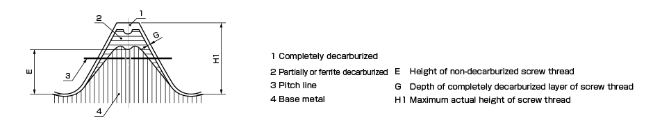
| Height of the thread's non-decarbonized part E | Min. | - | 1/2H1 | 2/3H1 | 3/4H1 | |||||||||
| Depth of completely decarburized layer of screw thread G [mm] | Max. | - | 0.015 | |||||||||||
(a) Does not apply to steel structural bolts.
(b) Steel structural bolts are d ≧ M12.
(c) Nominal values are used only for the purpose of expressing strength classifications.
(d) Where the lower yield point ReL cannot be found, specification is according to 0.2% yield strength Rp0.2.
(e) Rpf min values for strength classifications 4.8, 5.8, and 6.8 are under research. Presented values are given only for calculating guaranteed load stress ratios, and are not values derived from testing.
(f) Guaranteed load test strength is stipulated separately.
(g) Hardness found for the tip of the screw on male-screw components is equal to or lower than 250HV, 238HB, or 99.5HRB.
(h) Where both surface hardness and base metal hardness are being sought at HV0.3, the surface hardness must not be harder than the measured screw base metal hardness by more than 30 points on the Vickers scale.
(i) Values found at test temperature of − 20°C.
(j) Applies to d ≧ 16 mm.
(k) Value for Kv is under research.
(l) Where agreed between supplying and receiving parties, JIS B 1043 may be applied instead of JIS B 1041.
| Screw pitch P | 0.5 | 0.6 | 0.7 | 0.8 | 1 | 1.25 | 1.5 | 1.75 | 2 | 2.5 | 3 | 3.5 | 4 | ||
|---|---|---|---|---|---|---|---|---|---|---|---|---|---|---|---|
| H1 | 0.307 | 0.368 | 0.429 | 0.491 | 0.613 | 0.767 | 0.920 | 1.074 | 1.227 | 1.534 | 1.840 | 2.147 | 2.454 | ||
| E (Min.) |
Strength classification | 8.8,9.8 | 0.154 | 0.184 | 0.215 | 0.245 | 0.307 | 0.384 | 0.460 | 0.537 | 0.614 | 0.767 | 0.920 | 1.074 | 1.227 |
| 10.9 | 0.205 | 0.245 | 0.286 | 0.327 | 0.409 | 0.511 | 0.613 | 0.716 | 0.818 | 1.023 | 1.227 | 1.431 | 1.636 | ||
| 12.9 | 0.230 | 0.276 | 0.322 | 0.368 | 0.460 | 0.575 | 0.690 | 0.806 | 0.920 | 1.151 | 1.380 | 1.610 | 1.841 | ||
Mechanical Properties and Maximum Tightening Torque of Hexagon Socket Head Cap Screw (in Case of Strength Classification 10.9 and 12.9 Coarse Screw Threads)
| Nominal dia.(c) d | Effective crosssectional area [mm 2] |
Min. tensile load [N] |
Yield load [N] |
Guaranteed load [N] |
Max. allowable shaft force F [N] |
(Tf max.) Max. tightening torque[N・m] | |||||||
|---|---|---|---|---|---|---|---|---|---|---|---|---|---|
| K=0.17 | K=0.25 | ||||||||||||
| 10.9 | 12.9 | 10.9 | 12.9 | 10.9 | 12.9 | 10.9 | 12.9 | 10.9 | 12.9 | 10.9 | 12.9 | ||
| M1.6 | 1.27 | 1,320 | 1,550 | 1,190 | 1,390 | 1,050 | 1,230 | 832 | 976 | 0.23 | 0.27 | 0.33 | 0.39 |
| M2 | 2.07 | 2,150 | 2,530 | 1,940 | 2,270 | 1,720 | 2,010 | 1,360 | 1,590 | 0.46 | 0.54 | 0.68 | 0.80 |
| M2.5 | 3.39 | 3,530 | 4,140 | 3,170 | 3,720 | 2,810 | 3,290 | 2,220 | 2,610 | 0.94 | 1.11 | 1.39 | 1.63 |
| M3 | 5.03 | 5,230 | 6,140 | 4,710 | 5,520 | 4,180 | 4,880 | 3,300 | 3,870 | 1.68 | 1.97 | 2.47 | 2.90 |
| M4 | 8.78 | 9,130 | 10,700 | 8,220 | 9,640 | 7,290 | 8,520 | 5,750 | 6,750 | 3.91 | 4.59 | 5.75 | 6.75 |
| M5 | 14.2 | 14,800 | 17,300 | 13,300 | 15,600 | 11,800 | 13,800 | 9,300 | 10,900 | 7.91 | 9.28 | 11.6 | 13.6 |
| M6 | 20.1 | 20,900 | 24,500 | 18,800 | 22,100 | 16,700 | 19,500 | 13,200 | 15,400 | 13.4 | 15.8 | 19.8 | 23.2 |
| M8 | 36.6 | 38,100 | 44,600 | 34,300 | 40,200 | 30,400 | 35,500 | 24,000 | 28,100 | 32.6 | 38.3 | 48 | 56.3 |
| M10 | 58.0 | 60,300 | 70,800 | 54,300 | 63,700 | 48,100 | 56,300 | 38,000 | 44,600 | 64.6 | 75.8 | 95 | 111 |
| M12 | 84.3 | 87,700 | 103,000 | 78,900 | 92,600 | 70,000 | 81,800 | 55,200 | 64,800 | 113 | 132 | 166 | 194 |
| M14 | 115 | 120,000 | 140,000 | 108,000 | 126,000 | 95,500 | 112,000 | 75,300 | 88,400 | 179 | 210 | 264 | 309 |
| M16 | 157 | 163,000 | 192,000 | 147,000 | 172,000 | 130,000 | 152,000 | 103,000 | 121,000 | 280 | 328 | 411 | 483 |
| M18 | 192 | 200,000 | 234,000 | 180,000 | 211,000 | 159,000 | 186,000 | 126,000 | 148,000 | 385 | 452 | 566 | 664 |
| M20 | 245 | 255,000 | 299,000 | 229,000 | 269,000 | 203,000 | 238,000 | 161,000 | 188,000 | 546 | 640 | 803 | 942 |
| M22 | 303 | 315,000 | 370,000 | 284,000 | 333,000 | 252,000 | 294,000 | 199,000 | 233,000 | 742 | 871 | 1,090 | 1,280 |
| M24 | 353 | 367,000 | 431,000 | 330,000 | 388,000 | 293,000 | 342,000 | 231,000 | 271,000 | 944 | 1,110 | 1,390 | 1,630 |
| M27 | 459 | 477,000 | 560,000 | 430,000 | 504,000 | 381,000 | 445,000 | 301,000 | 353,000 | 1,380 | 1,620 | 2,030 | 2,380 |
| M30 | 561 | 583,000 | 684,000 | 525,000 | 616,000 | 466,000 | 544,000 | 368,000 | 431,000 | 1,870 | 2,200 | 2,760 | 3,230 |
K: Torque coefficient
- 1. The minimum tensile load and the guaranteed load in the table above are based on JIS B 1051-2000.
- 2. Yield load = yield strength (lower yield stress) x effective cross-sectional area
- 3. Max. allowable shaft force ≒ 0.7 x yield load, and max. tightening torque (Tfmax) = torque coefficient (K) x max. allowable shaft force (F) x nominal diameter (d).
- 4. In the case of torque coefficient K=0.17, oil lubrication, tightened material SS400, tightened surface finishing about 25S, female screw material SS400, and female screw accuracy 6 g or class 2 In the case of K=0.25, electrogalvanizing, tightened material SS400, tightened surface finishing about 25S, female screw material SCM, and female screw accuracy 6 g or class 2 Reference: If the female screw material is SS400 above, K=0.35.
Recommended Tightening Torque [Tf]
The recommended tightening torque (Tf) varies because the initial tightening force varies depending on the tool you use.
Recommended tightening torque (Tf) = tool-specific value x max. tightening torque (Tfmax)
- 1)Manual tightening : 0.65 Tfmax.
- 2)Impact driver or powered driver : 0.75 Tfmax.
- 3)Torque wrench or torque limiting wrench : 0.85 Tfmax.
- 4)Torque wrench : 0.9 Tfmax.
Other Technical Documents
- General Tolerances(Excerpt from JIS B 0405 1991/JIS B 0419 1991)
- MIKI PULLEY Coupling Standard Hole Drilling Standards
- MIKI PULLEY Clutch and Brake Standard Hole Drilling Standards
- Frequently Used Fits
- Fitting Tolerances(Excerpt from JIS B 0401)
- International System of Units (SI)
- Hexagon Socket Head Cap Bolts (Excerpt from JIS B 1176 2014)
- Hexagon Bolts (Excerpt from JIS B 1180 2014)
- Hexagon Socket Set Screws (Excerpt from JIS B 1177 2007)
- Hex Keys (Excerpt from JIS B 4648 2008)
- Parallel Key and Keyway Sizes and Tolerances
- Retaining Ring (Excerpt from JIS B 2804 2010)
- Bearing Mounting Dimensions