![]()
Learn machine components from beginning. What is ETP Bushing(Friction locking device/Hydraulic type) Deeply explain about it's role, structure & importat points how to use it.
What is ETP Bushing (Friction joint/hydraulic type)
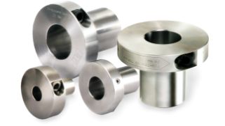
Component to fix hub on shaft with high precision by hydraulic Pascal principle.
Called as friction joint, moreover function rather than mechanical taper locking device. Widely used in Semicon, Food machinery, etc.
*For the detail → What is friction joint?
Function of ETP Bushing (Friction joint/hydraulic type)
Device developed for solving the problem in general fix method by key or set screw.
It is also called keyless bushing.
*For the detail → The role of friction joint
■Issues in key or set screw
| ■Problem of shaft | ■Problem of precision | ■Problem of vibration | |||
| Keyway or D-cut machining is necessary. There will be a risk of scratch, wearing and seizure of shaft after some period of working. |  |
Not easy to fix on shaft correct phase angle. Rotational unbalance and backlash is also problem for precise fixing. |  |
There will be a risk of key drop out or set screw loosen, device to prevent such risk is necessary. | 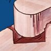 |
Feature & structure of ETP Bushing (Friction joint/hydraulic type)
*For the detail → ETP Bushing (Friction joint/hydraulic type)
■ETP-E Plus
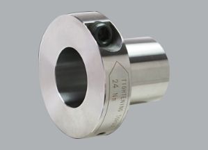
Quick fixing of hub & shaft available by only 1 bolt and high concentricity (0.02mm), suitable for frequent mount & dismount application with high precision. Tightening bolt from radial direction does not need wide space in axial direction.
■ Working Principal
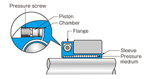
Pressure media move from chamber to sleeve by tightening pressure screw. Then sleeve will expand in both outer & inner direction to fix hub on shaft.
■ETP-T
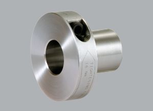
Quick fixing of hub & shaft available by only 1 bolt and high concentricity (0.006mm), suitable for frequent mount & dismount application with high precision. Tightening bolt from radial direction does not need wide space in axial direction.
■ Working Principal
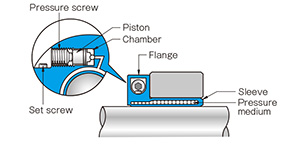
Pressure media move from chamber to sleeve by tightening pressure screw. Then sleeve will expand in both outer & inner direction to fix hub on shaft.
Pay attention when you use ETP Bushing (Friction joint/hydraulic type)
■Points of attention in production
1.Do not remove pressure screw and stopper screw (ETP-T only).
It cause pressure media leakage or inside pressure fluctuation, then hub does not fix on shaft correctly.
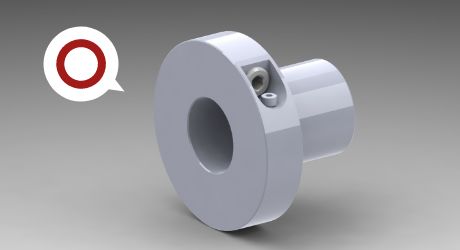
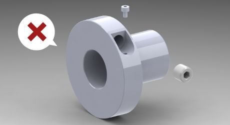
[NG] Complete remove of bolts.
2.Do not tighten bolt before inserting shaft & hub.
Sleeve will be deformed (plastic deformation), shaft & hub could not be inserted.
[NG] Tighten pressure screw before shaft & hub mounted.
3.Use calibrated torque wrench.
L shaped wrench with long shaft tends to generate over torque, ETP bushing will be damaged. Confirm tightening torque of ETP and use calibrated torque wrench to tighten pressure screw.
ETP- E Plus
Table of tightening torque & allowable difference of contact length(S)
*Tightening torque is common for same size with different surface treatment.
*Inner bore tolerance of hub is H7 for all size.
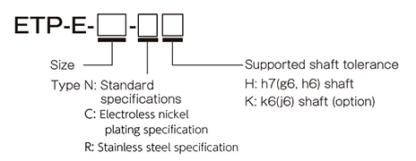
【How to view the model】
| Size | Type | Nominal diameter | Width across flat [mm] |
Tightening torque [N・m] |
Allowable length (S) [mm] |
||||
|---|---|---|---|---|---|---|---|---|---|
| ETP-E-015 | NH | CH | RH | - | - | M10 | 5 | 7 | 2 |
| ETP-E-019 | NH | CH | - | NK | CK | M10 | 5 | 7 | 2 |
| ETP-E-020 | NH | CH | RH | - | - | M10 | 5 | 7 | 2 |
| ETP-E-022 | NH | CH | - | NK | CK | M10 | 5 | 7 | 3 |
| ETP-E-024 | NH | CH | - | NK | CK | M10 | 5 | 7 | 3 |
| ETP-E-025 | NH | CH | RH | - | - | M10 | 5 | 7 | 3 |
| ETP-E-028 | NH | CH | - | NK | CK | M10 | 5 | 7 | 4 |
| ETP-E-030 | NH | CH | RH | - | - | M10 | 5 | 7 | 4 |
| ETP-E-032 | NH | CH | - | NK | CK | M10 | 5 | 7 | 4 |
| ETP-E-035 | NH | CH | RH | - | - | M10 | 5 | 7 | 4 |
| ETP-E-038 | NH | CH | - | NK | CK | M16 | 8 | 24 | 5 |
| ETP-E-040 | NH | CH | RH | - | - | M16 | 8 | 24 | 5 |
| ETP-E-042 | NH | CH | - | NK | CK | M16 | 8 | 24 | 5 |
| ETP-E-045 | NH | CH | RH | - | - | M16 | 8 | 24 | 5 |
| ETP-E-048 | NH | CH | - | NK | CK | M16 | 8 | 24 | 5 |
| ETP-E-050 | NH | CH | RH | - | - | M16 | 8 | 24 | 5 |
| ETP-E-055 | NH | CH | - | NK | CK | M16 | 8 | 24 | 5 |
| ETP-E-060 | NH | CH | RH | - | - | M16 | 8 | 24 | 5 |
| ETP-E-070 | NH | - | - | - | - | M20 | 10 | 40 | 8 |
| ETP-E-080 | NH | - | - | - | - | M20 | 10 | 40 | 8 |
| ETP-E-090 | NH | - | - | - | - | M20 | 10 | 40 | 8 |
| ETP-E-100 | NH | - | - | - | - | M20 | 10 | 40 | 8 |
ETP- T
Table of tightening torque / allowable difference of contact length(S)
*Inner bore tolerance of hub is H7 for all size.
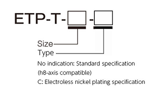
【How to view the model】
| Size | Type | Nominal diameter | Width across flat [mm] |
Tightening torque [N・m] |
Allowable length (S) [mm] |
|
|---|---|---|---|---|---|---|
| ETP-T-15 | Not listed | C | M12 | 6 | 12 | 5 |
| ETP-T-19 | Not listed | C | M12 | 6 | 12 | 5 |
| ETP-T-20 | Not listed | C | M12 | 6 | 12 | 5 |
| ETP-T-24 | Not listed | C | M14 | 6 | 16 | 5 |
| ETP-T-25 | Not listed | C | M14 | 6 | 16 | 6 |
| ETP-T-30 | Not listed | C | M14 | 6 | 16 | 6 |
| ETP-T-35 | Not listed | C | M14 | 6 | 16 | 6 |
| ETP-T-40 | Not listed | C | M16 | 8 | 24 | 7 |
| ETP-T-50 | Not listed | C | M16 | 8 | 24 | 8 |
| ETP-T-60 | Not listed | C | M20 | 10 | 40 | 9 |
| ETP-T-70 | Not listed | - | M20 | 10 | 40 | 10 |
| ETP-T-75 | Not listed | - | M20 | 10 | 40 | 10 |
| ETP-T-80 | Not listed | - | M20 | 10 | 40 | 10 |
| ETP-T-90 | Not listed | - | M22 | 10 | 60 | 10 |
| ETP-T-100 | Not listed | - | M24 | 12 | 80 | 10 |
4.Keep the number of times for mount & dismount.
Mount & dismount number of times depends on the model.(Refer to below table).
| Model | Number of mount & dismount times | |
|---|---|---|
| ETP-E(N) | ETP-E-015-N~035-N | 3000 |
| ETP-E-038-N~060-N | 2000 | |
| ETP-E-070-N~100-N | 750 | |
| ETP-E(C) | ETP-E-015-C~035-C | 1500 |
| ETP-E-038-C~060-C | 1000 | |
| ETP-E(R) | ETP-E-015-R~035-R | 1200 |
| ETP-E-040-R~060-R | 600 | |
| ETP-T | ETP-T-15~50 | 5000 |
| ETP-T-60~80 | 3000 | |
| ETP-T-90*100 | 500 | |
| ETP-T(C) | ETP-T-15-C~50-C | 5000 |
| ETP-T-60-C | 3000 | |
Always keep the pressure screw surface with oil or grease contain anti-frictional substances such as molybdenum, silicon, or fluorine, avoid attaching other substances.
■Points of attention in design
5.Check the allowable radial forces.
ETP bushing will be damaged if over radial force applied. Confirm allowable value in specification page.
*For the detail →Specification of ETP-E plus/ ETP-T
・Extreme examples of damage
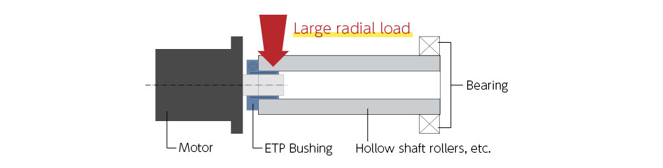
Reaction force generated by misalignment between motor shaft and hollow roller supporting bearing applied on ETP as an over radial force.
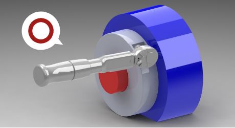
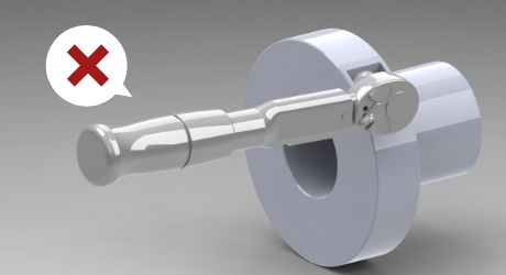
6. Be sure to confirm the length of shaft insert.
Insufficient inserting length of shaft & hub will cause damage on ETP or slipping torque. Design hub (gear, pulley, etc.) to secure even contact pressure by keeping allowable dimension (S).
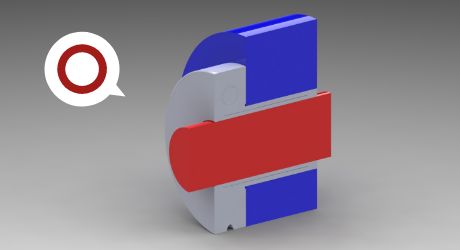
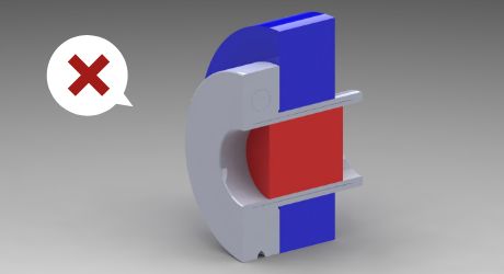
[NG] Shaft (red part) and hub (blue part) does not contact overall length.
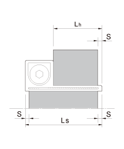
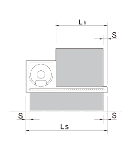
・Shaft & Hub end acceptable dimensions
ETP guarantee it's performance when the shaft & hub fully contact with ETP sleeve dimension LS and Lh. Design shaft and hub length accordingly. If in case the shaft and hub length are limited, design the difference within the dimension S as in below illustration. If the difference over dimension S, it may be impossible to dismount ETP by plastic deformation due to stress concentration at the sleeve end.
| Size of ETP-E Plus | S[mm] | |
|---|---|---|
 |
015 | 2 |
| 019 | 2 | |
| 020 | 2 | |
| 022 | 3 | |
| 024 | 3 | |
| 025 | 3 | |
| 028 | 4 | |
| 030 | 4 | |
| 032 | 4 | |
| 035 | 4 | |
| 038 | 5 | |
| 040 | 5 | |
| 042 | 5 | |
| 045 | 5 | |
| 048 | 5 | |
| 050 | 5 | |
| 055 | 5 | |
| 060 | 5 | |
| 070 | 8 | |
| 080 | 8 | |
| 090 | 8 | |
| 100 | 8 | |
| Size of ETP-T | S[mm] | |
|---|---|---|
 |
15 | 5 |
| 19 | 5 | |
| 20 | 5 | |
| 24 | 5 | |
| 25 | 6 | |
| 30 | 6 | |
| 35 | 6 | |
| 40 | 7 | |
| 50 | 8 | |
| 60 | 9 | |
| 70 | 10 | |
| 75 | 10 | |
| 80 | 10 | |
| 90 | 10 | |
| 100 | 10 | |
| - | - | |
| - | - | |
| - | - | |
| - | - | |
| - | - | |
| - | - | |
| - | - | |
7. Be sure to keep correct shaft diameter tolerance for the suitable model.
Shaft diameter /tolerance & hub inner bore diameter / tolerance must be matched with required value of the selected ETP model. Confirm the shaft tolerance when you chose the model.
・Shaft diameter tolerance , hub inner bore tolerance and surface roughness
| Model | Shaft diameter tolerance | Hub inner bore tolerance | Surface roughness | |
|---|---|---|---|---|
| ETP-EPlus | ETP-E-□-NH・CH・RH | h7(g6・h6) | H7 | 25S (center line average roughness less than 6.3a) |
| ETP-E-□-NK・CK | k6(j6) | |||
| ETP-T | ETP-T-□ | h8 | ||
| ETP-T-□-C | ||||