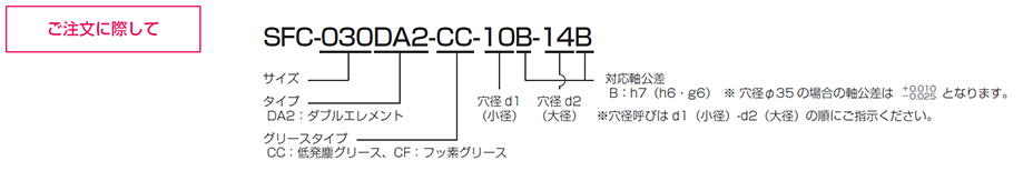
SFC [DA2] CC/CF: Low-Particle Design
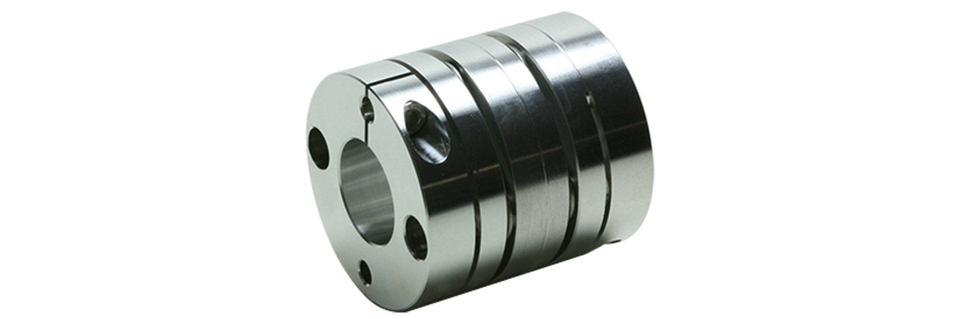
This is a simplified cleanroom-compatible solution that includes cleanroom cleaning, assembly, and clean packaging for the double-element type. The basic design is the same as the standard model, with modifications to the surface treatment of the main body and the use of stainless steel bolts. For the clamping bolts used to secure axial force, you can choose between two types of grease: fluorinated grease and low-dust grease.
[Specifications]
| Model | Type |
Allowable Torque [N·m] |
Tolerance | Maximum Rotational Speed [min⁻¹] |
Torsional spring constant [N·m/rad] |
Axial spring constant [N/mm] |
Moment of inertia [kg·m²] |
Mass [kg] |
Price [JPY] |
||
|---|---|---|---|---|---|---|---|---|---|---|---|
| Eccentricity [mm] |
Angular offset [°] |
Axial [mm] |
|||||||||
| SFC-020DA2 | C | 2 | 0.15 | 1 (per side) | ±0.33 | 10,000 | 1850 | 32 | 3.43×10⁻⁶ | 0.035 | - |
| SFC-025DA2 | C | 4 | 0.16 | 1 (per side) | ±0.38 | 10,000 | 2,800 | 30 | 5.26×10⁻⁶ | 0.040 | - |
| SFC-030DA2 | A | 5 | 0.18 | 1 (per side) | ±0.4 | 10,000 | 4,000 | 32 | 7.46×10⁻⁶ | 0.054 | - |
| B | 9.49×10⁻⁶ | 0.060 | - | ||||||||
| C | 11.60×10⁻⁶ | 0.069 | - | ||||||||
| SFC-035DA2 | C | 10 | 0.24 | 1 (per side) | ±0.5 | 10,000 | 9,000 | 56.2 | 27.03×10⁻⁶ | 0.122 | - |
| SFC-040DA2 | A | 12 | 0.24 | 1 (per side) | ±0.6 | 10,000 | 10,000 | 40 | 30.03×10⁻⁶ | 0.124 | - |
| B | 35.81×10⁻⁶ | 0.132 | - | ||||||||
| C | 42.60×10⁻⁶ | 0.147 | - | ||||||||
| SFC-050DA2 | A | 25 | 0.28 | 1 (per side) | ±0.8 | 10,000 | 16,000 | 24 | 99.32×10⁻⁶ | 0.252 | - |
| B | 119.8×10⁻⁶ | 0.270 | - | ||||||||
| C | 142.4×10⁻⁶ | 0.299 | - | ||||||||
| SFC-055DA2 | C | 40 | 0.31 | 1 (per side) | ±0.84 | 10,000 | 25,000 | 21.5 | 262.3×10⁻⁶ | 0.436 | - |
| SFC-060DA2 | A | 60 | 0.34 | 1 (per side) | ±0.9 | 10,000 | 35,000 | 38.2 | 258.6×10⁻⁶ | 0.450 | - |
| B | 317.8×10⁻⁶ | 0.493 | - | ||||||||
| C | 381.6×10⁻⁶ | 0.552 | - | ||||||||
| SFC-080DA2 | C | 100 | 0.52 | 1 (per side) | ±1.10 | 10,000 | 70,000 | 64 | 1047×10⁻⁶ | 1.050 | - |
- The shape type (A, B, or C) is automatically determined based on the combination of hole diameters you select, so you cannot specify it.
- The allowable torque may be limited by the holding force of the shaft fastening section, so please check the "standard bore diameter."
- The maximum rotational speed does not take dynamic balance into account.
- The torsional spring constant values are based solely on measurements taken of the element section.
- The moment of inertia and mass are based on the maximum bore diameter.
[Dimensions]
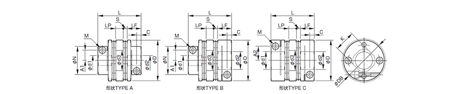
| Model | Shape TYPE | d1 | d2 | D | N | L | LF | LP | S | A1 | A2 | C | d3 | K | M | Tightening torque [N·m] | |||
|---|---|---|---|---|---|---|---|---|---|---|---|---|---|---|---|---|---|---|---|
| Minimum | Max | Min | Max | CC Low-dust | CF Fluorine | ||||||||||||||
| SFC-020DA2 | C | 5 | 10 | 5 | 11 | 26 | - | 32.3 | 10.75 | 7.5 | 1.65 | - | 9.5 | 3.3 | 10.6 | 10.6 | 1-M2.5 | 0.5 | 0.9 |
| SFC-025DA2 | C | 5 | 14 | 5 | 14 | 29 | - | 32.8 | 10.75 | 7.5 | 1.9 | - | 11 | 3.3 | 15 | 14.5 | 1-M2.5 | 0.5 | 0.9 |
| SFC-030DA2 | A | 5 | 10 | 5 | 10 | 34 | 21.6 | 37.8 | 12.4 | 8 | 2.5 | 8 | - | 3.75 | 15 | 14.5 | 1-M3 | 1.5 | 3.2 |
| B | Over 10 | 16 | |||||||||||||||||
| C | Over 10 | 14 | |||||||||||||||||
| SFC-035DA2 | C | 6 | 16 | 6 | 19 | 39 | - | 48 | 15.5 | 11 | 3 | - | 14 | 4.5 | 17 | 17 | 1-M4 | 4 | 7.7 |
| SFC-040DA2 | A | 8 | 15 | 8 | 15 | 44 | 29.6 | 48 | 15.5 | 11 | 3 | 11 | - | 4.5 | 20 | 19.5 | 1-M4 | 4 | 7.7 |
| B | Exceeding 15 | 24 | |||||||||||||||||
| C | Over 15 | 24 | |||||||||||||||||
| SFC-050DA2 | A | 8 | 19 | 8 | 19 | 56 | 38 | 59.8 | 20.5 | 14 | 2.4 | 14.5 | - | 6 | 26 | 26 | 1-M5 | 7 | 12 |
| B | Over 19 | 30 | |||||||||||||||||
| C | Over 19 | 25 | |||||||||||||||||
| SFC-055DA2 | C | 10 | 30 | 10 | 30 | 63 | - | 68.7 | 24 | 15.5 | 2.6 | - | 23 | 7.75 | 31 | 31 | 1-M6 | 13 | 22.5 |
| SFC-060DA2 | A | 11 | 24 | 11 | 24 | 68 | 46 | 73.3 | 25.2 | 16.5 | 3.2 | 17.5 | - | 7.75 | 31 | 31 | 1-M6 | 13 | 22.5 |
| B | Over 24 | 35 | |||||||||||||||||
| C | Over 24 | 30 | |||||||||||||||||
| SFC-080DA2 | C | 18 | 35 | 18 | 40 | 82 | - | 98 | 30 | 22 | 8 | - | 28 | 9 | 40 | 38 | 1-M8 | 27 | 45 |
- The shape type (A, B, or C) is automatically determined based on the combination of hole diameters you select, so you cannot specify it.
- Dimension K is the inner diameter of the element. If dimension d2 exceeds this value, the shaft can only be inserted into the hub on the d2 side up to dimension LF.
- The designation for Clamp Bolt M is based on the number of threads and the thread size; the number refers to the number of threads on one side of the hub.
- Please choose from two types of grease for clamping bolts used to secure axial force: low-dust grease and fluorinated grease.
[Standard Bore Diameter] (Low-dust grease specification)
| Model | Standard (Optional) Bore Diameter d1・d2 [mm] and Maximum Torque [N・m] | |||||||||||||||||||||||||||
|---|---|---|---|---|---|---|---|---|---|---|---|---|---|---|---|---|---|---|---|---|---|---|---|---|---|---|---|---|
| d1・d2 | 5 | 6 | 6.35 | 7 | 8 | 9 | 9.525 | 10 | 11 | 12 | 13 | 14 | 15 | 16 | 17 | 18 | 19 | 20 | 22 | 24 | 25 | 28 | 30 | 32 | 35 | 38 | 40 | |
| SFC-020DA2 | d1 | 0.5 | 0.6 | 0.6 | 0.6 | 1 | 1.3 | 1.3 | ● | |||||||||||||||||||
| d2 | 0.5 | 0.6 | 0.6 | 0.6 | 1 | 1.3 | 1.3 | ● | ● | |||||||||||||||||||
| SFC-025DA2 | d1 | 0.5 | 0.5 | 0.5 | 0.5 | 0.8 | 0.8 | 0.8 | 1.8 | 1.8 | 2.3 | 2.3 | ● | |||||||||||||||
| d2 | 0.5 | 0.5 | 0.5 | 0.5 | 0.8 | 0.8 | 0.8 | 1.8 | 1.8 | 2.3 | 2.3 | ● | ||||||||||||||||
| SFC-030DA2 | d1 | 0.8 | 1.6 | 2 | 2.6 | 3.4 | 4.4 | 4.9 | ● | ● | ● | ● | ● | |||||||||||||||
| d2 | 0.8 | 1.6 | 2 | 2.6 | 3.4 | 4.4 | 4.9 | ● | ● | ● | ● | ● | ● | ● | ||||||||||||||
| SFC-035DA2 | d1 | 3.3 | 3.8 | 4.8 | 6.3 | 7.7 | 8.5 | 9.2 | ● | ● | ● | ● | ● | ● | ||||||||||||||
| d2 | 3.3 | 3.8 | 4.8 | 6.3 | 7.7 | 8.5 | 9.2 | ● | ● | ● | ● | ● | ● | ● | ● | ● | ||||||||||||
| SFC-040DA2 | d1 | 9 | 9 | 9 | 9 | 9 | ● | ● | ● | ● | ● | ● | ● | ● | ||||||||||||||
| d2 | 9 | 9 | 9 | 9 | 9 | ● | ● | ● | ● | ● | ● | ● | ● | ● | ● | ● | ||||||||||||
| SFC-050DA2 | d1 | 11 | 16 | 17 | 19 | 19 | 24 | 24 | 24 | ● | ● | ● | ● | ● | ● | ● | ● | ● | ||||||||||
| d2 | 11 | 16 | 17 | 19 | 19 | 24 | 24 | 24 | ● | ● | ● | ● | ● | ● | ● | ● | ● | ● | ● | |||||||||
| SFC-055DA2 | d1 | 20 | 24 | 29 | 33 | 37 | ● | ● | ● | ● | ● | ● | ● | ● | ● | ● | ● | |||||||||||
| d2 | 20 | 24 | 29 | 33 | 37 | ● | ● | ● | ● | ● | ● | ● | ● | ● | ● | ● | ||||||||||||
| SFC-060DA2 | d1 | 38 | 41 | 44 | 48 | 55 | 55 | 58 | ● | ● | ● | ● | ● | ● | ● | ● | ||||||||||||
| d2 | 38 | 41 | 44 | 48 | 55 | 55 | 58 | ● | ● | ● | ● | ● | ● | ● | ● | ● | ● | |||||||||||
| SFC-080DA2 | d1 | 54 | 60 | 65 | 75 | 85 | 90 | ● | ● | ● | ● | |||||||||||||||||
| d2 | 54 | 60 | 65 | 75 | 85 | 90 | ● | ● | ● | ● | ● | ● | ||||||||||||||||
- The standard bore diameter for shaft tolerance h7 (h6/g6) is nominal B. However, for a bore diameter of φ35, the shaft tolerance is -0.025 to +0.010.
- The hole diameters indicated by the ● symbol and numerical values in the corresponding columns are standard sizes. For hole diameters not listed in the table above, we may be able to accommodate your request; please contact us for details.
- Because the hole diameter in the column containing the numerical values is small, the allowable torque is limited by the holding force at the shaft fastening point. The numerical values indicate the allowable torque [N·m].
[Standard Bore Diameter] (Fluorinated Grease Specification)
| Model | Standard (Optional) Bore Diameter d1・d2 [mm] and Maximum Torque [N・m] | |||||||||||||||||||||||||||
|---|---|---|---|---|---|---|---|---|---|---|---|---|---|---|---|---|---|---|---|---|---|---|---|---|---|---|---|---|
| d1・d2 | 5 | 6 | 6.35 | 7 | 8 | 9 | 9.525 | 10 | 11 | 12 | 13 | 14 | 15 | 16 | 17 | 18 | 19 | 20 | 22 | 24 | 25 | 28 | 30 | 32 | 35 | 38 | 40 | |
| SFC-020DA2 | d1 | 0.7 | 0.7 | 0.7 | 0.8 | ● | ● | ● | ● | ● | ||||||||||||||||||
| SFC-020DA2 | d2 | 0.7 | 0.7 | 0.7 | 0.8 | ● | ● | ● | ● | ● | ● | |||||||||||||||||
| SFC-025DA2 | d1 | 0.5 | 0.5 | 0.5 | 1.1 | 1.6 | 1.6 | 1.6 | 3.2 | 3.2 | ● | ● | ● | |||||||||||||||
| SFC-025DA2 | d2 | 0.5 | 0.5 | 0.5 | 1.1 | 1.6 | 1.6 | 1.6 | 3.2 | 3.2 | ● | ● | ● | |||||||||||||||
| SFC-030DA2 | d1 | 0.8 | 0.8 | 2 | 2.4 | 3.1 | 4.3 | ● | ● | ● | ● | ● | ● | ● | ||||||||||||||
| SFC-030DA2 | d2 | 0.8 | 0.8 | 2 | 2.4 | 3.1 | 4.3 | ● | ● | ● | ● | ● | ● | ● | ● | |||||||||||||
| SFC-035DA2 | d1 | 3.6 | 5.2 | 6.4 | 8.2 | ● | ● | ● | ● | ● | ● | ● | ● | ● | ● | |||||||||||||
| SFC-035DA2 | d2 | 3.6 | 5.2 | 6.4 | 8.2 | ● | ● | ● | ● | ● | ● | ● | ● | ● | ● | ● | ● | |||||||||||
| SFC-040DA2 | d1 | ● | ● | ● | ● | ● | ● | ● | ● | ● | ● | ● | ● | ● | ||||||||||||||
| SFC-040DA2 | d2 | ● | ● | ● | ● | ● | ● | ● | ● | ● | ● | ● | ● | ● | ● | ● | ● | |||||||||||
| SFC-050DA2 | d1 | 11 | 17 | 19 | 20 | 22 | ● | ● | ● | ● | ● | ● | ● | ● | ● | ● | ● | ● | ||||||||||
| SFC-050DA2 | d2 | 11 | 17 | 19 | 20 | 22 | ● | ● | ● | ● | ● | ● | ● | ● | ● | ● | ● | ● | ● | ● | ||||||||
| SFC-055DA2 | d1 | 28 | 37 | ● | ● | ● | ● | ● | ● | ● | ● | ● | ● | ● | ● | ● | ● | |||||||||||
| SFC-055DA2 | d2 | 28 | 37 | ● | ● | ● | ● | ● | ● | ● | ● | ● | ● | ● | ● | ● | ● | |||||||||||
| SFC-060DA2 | d1 | 40 | 44 | 49 | 53 | ● | ● | ● | ● | ● | ● | ● | ● | ● | ● | ● | ||||||||||||
| SFC-060DA2 | d2 | 40 | 44 | 49 | 53 | ● | ● | ● | ● | ● | ● | ● | ● | ● | ● | ● | ● | ● | ||||||||||
| SFC-080DA2 | d1 | 60 | 66 | 71 | 81 | 90 | 95 | ● | ● | ● | ● | |||||||||||||||||
| SFC-080DA2 | d2 | 60 | 66 | 71 | 81 | 90 | 95 | ● | ● | ● | ● | ● | ● | |||||||||||||||
- The standard bore diameter for shaft tolerance h7 (h6/g6) is designation B. However, for a bore diameter of φ35, the shaft tolerance is -0.025 to +0.010.
- The hole diameters indicated by the ● symbol and numerical values in the corresponding columns are standard sizes. For hole diameters not listed in the table above, we may be able to accommodate your request; please contact us for details.
- Because the hole diameter in the column containing the numerical values is small, the allowable torque is limited by the holding force at the shaft fastening point. The numerical values indicate the allowable torque [N·m].