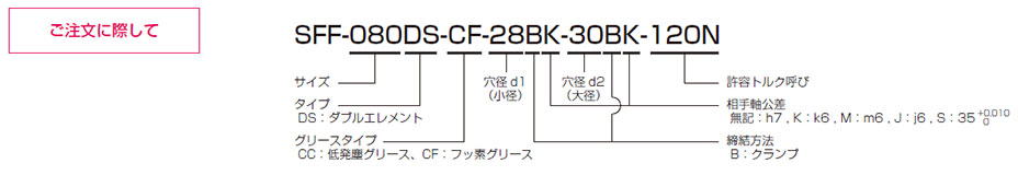
SFF [DS-CC/CF] ISO Class 6 Cleanroom Version Type_53
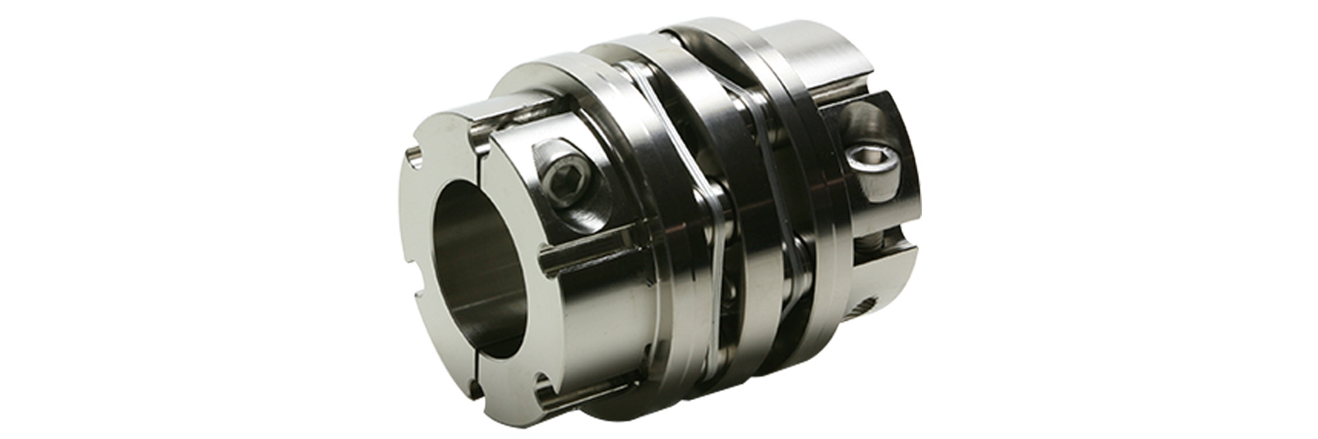
This is a simplified cleanroom-compatible product featuring the SFF model of a double-element coupling for servo motor drives used in feed shafts, which has been treated with electroless nickel plating and undergoes cleanroom cleaning, assembly, and packaging.For the grease used on the clamping bolts to ensure axial force, you can choose from two types: fluorinated grease and low-dust grease.
[Specifications] Clamp-fastening type
| Model | Rated Torque [N·m] |
Tolerance | Maximum Rotational Speed [min⁻¹] |
Torsional spring constant [N·m/rad] |
Axial spring constant [N/mm] |
Moment of inertia [kg·m²] |
Mass [kg] |
Price [JPY] |
||
|---|---|---|---|---|---|---|---|---|---|---|
| Eccentricity [mm] |
Angular offset [°] |
Axial length [mm] |
||||||||
| SFF-040DS-□-□B-□B-8N | 8 | 0.1 | 1 (one side) | ±0.4 | 14,000 | 7,500 | 87 | 0.04×10⁻³ | 0.22 | - |
| SFF-050DS-□-□B-□B-16N | 16 | 0.2 | 1 (per side) | ±0.6 | 14,000 | 16,000 | 72.5 | 0.13×10⁻³ | 0.46 | - |
| SFF-060DS-□-□B-□B-40N | 40 | 0.2 | 1 (per side) | ±0.6 | 14,000 | 52,000 | 199.5 | 0.28×10⁻³ | 0.64 | - |
| SFF-060DS-□-□B-□B-50N | 50 | 0.2 | 1 (per side) | ±0.6 | 14,000 | 52,000 | 199.5 | 0.29×10⁻³ | 0.61 | - |
| SFF-070DS-□-□B-□B-65N | 65 | 0.25 | 1 (one side) | ±1.0 | 14,000 | 120,000 | 242 | 0.53×10⁻³ | 0.90 | - |
| SFF-080DS-□-□B-□B-120N | 120 | 0.31 | 1 (one side) | ±1.0 | 13,000 | 155,000 | 273 | 1.50×10⁻³ | 1.72 | - |
| SFF-090DS-□-□B-□B-150N | 150 | 0.32 | 1 (per side) | ±1.2 | 12,000 | 260,000 | 160.5 | 2.03×10⁻³ | 2.02 | - |
| SFF-100DS-□-□B-□B-250N | 250 | 0.38 | 1 (per side) | ±1.3 | 10,000 | 370,000 | 270 | 4.18×10⁻³ | 3.12 | - |
- The maximum rotational speed does not take dynamic balance into account.
- The torsional spring constant value refers to the value for a single element.
- The moment of inertia and mass are based on the maximum bore diameter.
[Dimensions] Clamp-type

| Model | d1 | d2 | D | L | N1・N2 | LF | LP | S | d3 | K | M1・M2 | Tightening torque [N·m] | |
|---|---|---|---|---|---|---|---|---|---|---|---|---|---|
| [mm] | [mm] | [mm] | [mm] | [mm] | [mm] | [mm] | [mm] | [mm] | [mm] | Quantity-Nominal | CC Low-Dust | CF Fluorine | |
| SFF-040DS-□-□B-□B-8N | 8–16 | 8–16 | 38 | 48.8 | 33 | 17.5 | 6 | 3.9 | 17 | 17 | 2-M4 | 4.5 | 4.5 |
| SFF-050DS-□-□B-□B-16N | 10–19 | 10–19 | 48 | 60.8 | 42 | 21.5 | 7 | 5.4 | 20 | 20 | 2-M5 | 9 | 8.5 |
| SFF-060DS-□-□B-□B-40N | 12–22 | 12–22 | 58 | 65.8 | 44 | 24 | 7 | 5.4 | 31 | 32 | 2-M6 | 16 | 16 |
| - | 24–28 | 58 | 65.8 | 48 | 24 | 7 | 5.4 | 31 | 32 | 2-M5 | 9 | 8.5 | |
| - | 30 | 58 | 65.8 | 52 | 24 | 7 | 5.4 | 31 | 32 | 2-M5 | 9 | 8.5 | |
| SFF-060DS-□-□B-□B-50N | 24–28 | 24–28 | 58 | 65.8 | 48 | 24 | 7 | 5.4 | 31 | 32 | 2-M5 | 9 | 8.5 |
| 30 | 30 | 58 | 68.5 | 52 | 24 | 7 | 5.4 | 31 | 32 | 2-M5 | 9 | 8.5 | |
| SFF-070DS-□-□B-□B-65N | 18–19 | 18–25 | 68 | 69.8 | 47 | 25 | 8 | 5.9 | 37 | 38 | 2-M6 | 16 | 16 |
| - | 28–35 | 68 | 69.8 | 56 | 25 | 8 | 5.9 | 37 | 38 | 2-M6 | 16 | 16 | |
| SFF-080DS-□-□B-□B-120N | 28–35 | 28–35 | 78 | 85.4 | 70 | 30 | 10 | 7.7 | 40 | 42 | 2-M8 | 37 | 45 |
| 38 | 38 | 78 | 85.4 | 74 | 30 | 10 | 7.7 | 40 | 42 | 2-M8 | 37 | 45 | |
| SFF-090DS-□-□B-□B-150N | 35–42 | 35–42 | 88 | 86.6 | 74 | 30 | 10 | 8.3 | 50 | 50 | 2-M8 | 37 | 45 |
| SFF-100DS-□-□B-□B-250N | 38–48 | 38–48 | 98 | 112.4 | 84 | 40 | 12 | 10.2 | 52 | 56 | 2-M10 | 68 | 65 |
- The designation for M1 and M2 clamp bolts consists of the quantity followed by the thread size; the quantity refers to the number of bolts on one side of the hub.
- Please choose from two types of grease for clamping bolts used to secure axial force: low-dust grease and fluorinated grease.
[Standard Hole Diameter] Clamp-type fastening
| Model | Standard Hole Diameter d1・d2 [mm] | ||||||||||||||||||||||||
|---|---|---|---|---|---|---|---|---|---|---|---|---|---|---|---|---|---|---|---|---|---|---|---|---|---|
| 8 | 9 | 9.525 | 10 | 11 | 12 | 14 | 15 | 16 | 17 | 18 | 19 | 20 | 22 | 24 | 25 | 28 | 30 | 32 | 35 | 38 | 40 | 42 | 45 | 48 | |
| SFF-040DS-□-□B-□B-8N | ● | ● | ● | ● | ● | ● | ● | ● | ● | ||||||||||||||||
| SFF-050DS-□-□B-□B-16N | ● | ● | ● | ● | ● | ● | ● | ● | ● | ||||||||||||||||
| SFF-060DS-□-□B-□B-40N | ● | ● | ● | ● | ● | ● | ● | ● | ● | ● | ● | ● | ● | ||||||||||||
| SFF-060DS-□-□B-□B-50N | ● | ● | ● | ● | |||||||||||||||||||||
| SFF-070DS-□-□B-□B-65N | ● | ● | ● | ● | ● | ● | ● | ● | ● | ● | |||||||||||||||
| SFF-080DS-□-□B-□B-120N | ● | ● | ● | ● | ● | ||||||||||||||||||||
| SFF-090DS-□-□B-□B-150N | ● | ● | ● | ● | |||||||||||||||||||||
| SFF-100DS-□-□B-□B-250N | ● | ● | ● | ● | |||||||||||||||||||||
- The hole diameters in the fields marked with a ● are the standard hole diameters.