
SFC [DA2] Type

This disk-type coupling features a clamping hub made of a lightweight, high-strength aluminum alloy, providing high torsional stiffness and enabling High Dynamic Performance. Additionally, the hub’s outside diameter is designed to match the shaft diameter, which helps reduce the moment of inertia. The DA2 type is a model with High Torsional Stiffness and a double element design.
Specifications (Standard)
| models | Permissible (operating) torque [N·m] | Permissible Tolerance | Max. rotation speed [min⁻¹] | Torsional stiffness [N·m/rad] | Axial stiffness [N/mm] | Type | Moment of Inertia [kg·m²] | Mass [kg] | ||
|---|---|---|---|---|---|---|---|---|---|---|
| Eccentricity [mm] | Angular Misalignment [°] | In the axial direction [mm] | ||||||||
| SFC-002DA2 | 0.25 | 0.03 | 0.5 (one side) | ±0.08 | 10,000 | 95 | 17 | C | 0.07×10⁻⁶ | 0.004 |
| SFC-005DA2 | 0.6 | 0.05 | 0.5 (one side) | ±0.1 | 10,000 | 250 | 70 | C | 0.37×10⁻⁶ | 0.010 |
| SFC-010DA2 | 1 | 0.11 | 1 (one side) | ±0.2 | 10,000 | 700 | 70 | C | 0.80×10⁻⁶ | 0.015 |
| SFC-020DA2 | 2 | 0.15 | 1 (one side) | ±0.33 | 10,000 | 1,850 | 32 | C | 3.43×10⁻⁶ | 0.035 |
| SFC-025DA2 | 4 | 0.16 | 1 (per side) | ±0.38 | 10,000 | 2,800 | 30 | C | 5.26×10⁻⁶ | 0.040 |
| SFC-030DA2 | 5 | 0.18 | 1 (per side) | ±0.4 | 10,000 | 4,000 | 32 | A | 7.43×10⁻⁶ | 0.054 |
| B | 9.45×10⁻⁶ | 0.060 | ||||||||
| C | 11.56×10⁻⁶ | 0.068 | ||||||||
| SFC-035DA2 | 10 | 0.24 | 1 (per side) | ±0.5 | 10,000 | 9,000 | 56 | C | 26.93×10⁻⁶ | 0.121 |
| SFC-040DA2 | 12 | 0.24 | 1 (per side) | ±0.6 | 10,000 | 10,000 | 40 | A | 29.98×10⁻⁶ | 0.124 |
| B | 35.82×10⁻⁶ | 0.131 | ||||||||
| C | 42.52×10⁻⁶ | 0.146 | ||||||||
| SFC-050DA2 | 25 | 0.28 | 1 (per side) | ±0.8 | 10,000 | 16,000 | 24 | A | 98.34×10⁻⁶ | 0.250 |
| B | 118.9×10⁻⁶ | 0.268 | ||||||||
| C | 141.7×10⁻⁶ | 0.298 | ||||||||
| SFC-055DA2 | 40 | 0.31 | 1 (per side) | ±0.84 | 10,000 | 25,000 | 21.5 | C | 261.3×10⁻⁶ | 0.459 |
| SFC-060DA2 | 60 | 0.34 | 1 (per side) | ±0.9 | 10,000 | 35,000 | 38.2 | A | 256.6×10⁻⁶ | 0.447 |
| B | 315.7×10⁻⁶ | 0.489 | ||||||||
| C | 379.3×10⁻⁶ | 0.549 | ||||||||
| SFC-080DA2 | 100 | 0.52 | 1 (per side) | ±1.10 | 10,000 | 70,000 | 64 | C | 1039×10−6 | 1.037 |
| SFC-090DA2 | 180 | 0.52 | 1 (one side) | ±1.30 | 10,000 | 50,000 | 54 | C | 1798×10−6 | 1.369 |
| SFC-100DA2 | 250 | 0.55 | 1 (one side) | ±1.48 | 10,000 | 60,000 | 55.5 | C | 2754×10−6 | 1.739 |
- The shape TYPE (A, B, or C) is automatically determined based on the combination of bore sizes you select, so you cannot specify it.
- The permissible torque may be limited by the holding power of the shaft fastening section, so please verify it using the standard bore size.
- The max. rotation speed does not take dynamic balance into account.
- The torsional stiffness values are based solely on measurements taken from the element section.
- The moment of inertia and mass are the values corresponding to the maximum bore size.
Dimensions (Standard)
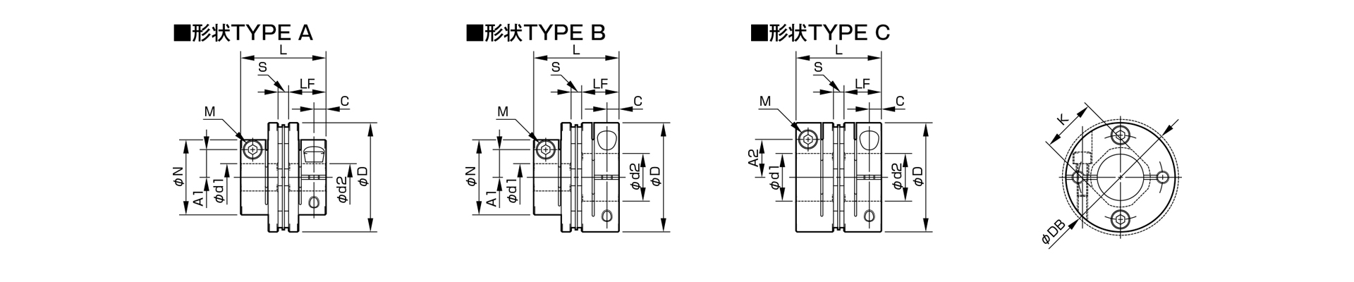
| models | d1 (Min.) | d1 Max | Min. d2 | d2 Max | D | DB | N | L | LF | LP | S | A1 | A2 | C | d3 | K | M | Tightening Torque [N·m] | Type |
|---|---|---|---|---|---|---|---|---|---|---|---|---|---|---|---|---|---|---|---|
| SFC-002DA2 | 3 | 5 | 3 | 5 | 12 | 12.4 | ─ | 15.7 | 5.9 | 2.8 | 0.55 | ─ | 3.7 | 1.9 | 5.2 | 5.6 | 1-M1.6 | 0.23–0.28 | C |
| SFC-005DA2 | 3 | 6 | 3 | 6 | 16 | ─ | ─ | 23.2 | 7.85 | 5.5 | 1 | ─ | 4.8 | 2.5 | 6.5 | 6.5 | 1-M2 | 0.4–0.5 | C |
| SFC-010DA2 | 3 | 8 | 3 | 8 | 19 | ─ | ─ | 25.9 | 9.15 | 5.5 | 1.05 | ─ | 5.8(6) | 3.15 | 8.5 | 8.5 | 1–M2.5 (M2) | 1.0–1.1 (0.4–0.5) | C |
| SFC-020DA2 | 4 | 10 | 4 | 11 | 26 | ─ | ─ | 32.3 | 10.75 | 7.5 | 1.65 | ─ | 9.5 | 3.3 | 10.6 | 10.6 | 1-M2.5 | 1.0–1.1 | C |
| SFC-025DA2 | 5 | 14 | 5 | 14 | 29 | ─ | ─ | 32.8 | 10.75 | 7.5 | 1.9 | ─ | 11 | 3.3 | 15 | 14.5 | 1–M2.5 | 1.0–1.1 | C |
| SFC-030DA2 | 5 | 10 | 5 | 10 | 34 | ─ | 21.6 | 37.8 | 12.4 | 8 | 2.5 | 8 | ─ | 3.75 | 15 | 14.5 | 1-M3 | 1.5–1.9 | A |
| 5 | 10 | Over 10 | 16 | 8 | 12.5 | B | |||||||||||||
| Over 10 | 14 | Over 10 | 16 | ─ | 12.5 | C | |||||||||||||
| SFC-035DA2 | 6 | 16 | 6 | 19 | 39 | ─ | ─ | 48 | 15.5 | 11 | 3 | ─ | 14 | 4.5 | 17 | 17 | 1-M4 | 3.4–4.1 | C |
| SFC-040DA2 | 8 | 15 | 8 | 15 | 44 | ─ | 29.6 | 48 | 15.5 | 11 | 3 | 11 | ─ | 4.5 | 20 | 19.5 | 1-M4 | 3.4–4.1 | A |
| 8 | 15 | Greater than 15 | 24 | 11 | 17 | B | |||||||||||||
| Over 15 | 19 | Over 15 | 24 | ─ | 17 | C | |||||||||||||
| SFC-050DA2 | 8 | 19 | 8 | 19 | 56 | ─ | 38 | 59.8 | 20.5 | 14 | 2.4 | 14.5 | ─ | 6 | 26 | 26 | 1-M5 | 7.0–8.5 | A |
| 8 | 19 | Greater than 19 | 30 | 14.5 | 22 | B | |||||||||||||
| Over 19 | 25 | Over 19 | 30 | ─ | 22 | C | |||||||||||||
| SFC-055DA2 | 10 | 30 | 10 | 30 | 63 | ─ | ─ | 68.7 | 24 | 15.5 | 2.6 | ─ | 23 | 7.75 | 31 | 31 | 1-M6 | 14–15 | C |
| SFC-060DA2 | 11 | 24 | 11 | 24 | 68 | ─ | 46 | 73.3 | 25.2 | 16.5 | 3.2 | 17.5 | ─ | 7.75 | 31 | 31 | 1-M6 | 14–15 | A |
| 11 | 24 | Over 24 | 35 | 17.5 | 26.5 | B | |||||||||||||
| Over 24 | 30 | Over 24 | 35 | ─ | 26.5 | C | |||||||||||||
| SFC-080DA2 | 18 | 35 | 18 | 40 | 82 | ─ | ─ | 98 | 30 | 22 | 8 | ─ | 28 | 9 | 40 | 38 | 1-M8 | 27–30 | C |
| SFC-090DA2 | 25 | 40 | 25 | 45 | 94 | ─ | ─ | 98.6 | 30 | 22 | 8.3 | ─ | 34 | 9 | 47 | 42 | 1-M8 | 27–30 | C |
| SFC-100DA2 | 32 | 45 | 32 | 45 | 104 | ─ | ─ | 101.6 | 30 | 22 | 9.8 | ─ | 39 | 9 | 50 | 48 | 1-M8 | 27–30 | C |
- The shape TYPE (A, B, or C) is automatically determined based on the combination of bore sizes you select, so you cannot specify it.
- The φDB dimension is the measurement taken when the head of the clamping bolt protrudes beyond the outside diameter of the hub.
- The nominal size for Clamping Bolt M is the quantity followed by the thread size; the quantity refers to the number of hubs on one side.
- The numbers in parentheses for SFC-010 are the values when d1 or d2 is φ8 mm.
Standard Bore Size (Standard)
| Standard (Optional) Bore Sizes d1 and d2 [mm] and Permissible Torque [N·m] | ||||||||||||||||||||||||||||||||
|---|---|---|---|---|---|---|---|---|---|---|---|---|---|---|---|---|---|---|---|---|---|---|---|---|---|---|---|---|---|---|---|---|
| Nominal Bore Size | 3 | 4 | 5 | 6 | 6.35 | 7 | 8 | 9 | 9.525 | 10 | 11 | 12 | 13 | 14 | 15 | 16 | 17 | 18 | 19 | 20 | 22 | 24 | 25 | 28 | 30 | 32 | 35 | 38 | 40 | 42 | 45 | |
| Shaft Tolerance: h7 (h6, g6) | B | ● | ● | ● | ● | ● | ● | ● | ● | ● | ● | ● | ● | ● | ● | ● | ● | ● | ● | ● | ● | ● | ● | ● | ● | ● | ● | ● | ● | ● | ● | ● |
| Shaft Tolerance: j6 (optional) | J | ○ | ○ | ○ | ○ | |||||||||||||||||||||||||||
| Shaft Tolerance: k6 (Optional) | K | ○ | ○ | ○ | ○ | ○ | ○ | ○ | ○ | ○ | ||||||||||||||||||||||
| SFC-002DA2 | d1 | ● | ● | ● | ||||||||||||||||||||||||||||
| SFC-002DA2 | d2 | ● | ● | ● | ||||||||||||||||||||||||||||
| SFC-005DA2 | d1 | ● | ● | ● | ● | |||||||||||||||||||||||||||
| SFC-005DA2 | d2 | ● | ● | ● | ● | |||||||||||||||||||||||||||
| SFC-010DA2 | d1 | ● | ● | ● | ● | ● | ● | ● | ||||||||||||||||||||||||
| SFC-010DA2 | d2 | ● | ● | ● | ● | ● | ● | ● | ||||||||||||||||||||||||
| SFC-020DA2 | d1 | ● | ● | ● | ● | ● | ● | ● | ● | ● | ||||||||||||||||||||||
| SFC-020DA2 | d2 | ● | ● | ● | ● | ● | ● | ● | ● | ● | ● | |||||||||||||||||||||
| SFC-025DA2 | d1 | 2.1 | ● | ● | ● | ● | ● | ● | ● | ● | ● | ● | ● | |||||||||||||||||||
| SFC-025DA2 | d2 | 2.1 | ● | ● | ● | ● | ● | ● | ● | ● | ● | ● | ● | |||||||||||||||||||
| SFC-030DA2 | d1 | 2.8 | 3.4 | ● | ● | ● | ● | ● | ● | ● | ● | ● | ● | |||||||||||||||||||
| SFC-030DA2 | d2 | 2.8 | 3.4 | ● | ● | ● | ● | ● | ● | ● | ● | ● | ● | ● | ● | |||||||||||||||||
| SFC-035DA2 | d1 | 5 | 5 | 6.6 | ● | ● | ● | ● | ● | ● | ● | ● | ● | ● | ||||||||||||||||||
| SFC-035DA2 | d2 | 5 | 5 | 6.6 | ● | ● | ● | ● | ● | ● | ● | ● | ● | ● | ● | ● | ● | |||||||||||||||
| SFC-040DA2 | d1 | 9 | ● | ● | ● | ● | ● | ● | ● | ● | ● | ● | ● | ● | ||||||||||||||||||
| SFC-040DA2 | d2 | 9 | ● | ● | ● | ● | ● | ● | ● | ● | ● | ● | ● | ● | ● | ● | ● | |||||||||||||||
| SFC-050DA2 | d1 | 18 | 20 | 22 | 22 | ● | ● | ● | ● | ● | ● | ● | ● | ● | ● | ● | ● | ● | ||||||||||||||
| SFC-050DA2 | d2 | 18 | 20 | 22 | 22 | ● | ● | ● | ● | ● | ● | ● | ● | ● | ● | ● | ● | ● | ● | ● | ||||||||||||
| SFC-055DA2 | d1 | 31 | 34 | 36 | 38 | ● | ● | ● | ● | ● | ● | ● | ● | ● | ● | ● | ● | |||||||||||||||
| SFC-055DA2 | d2 | 31 | 34 | 36 | 38 | ● | ● | ● | ● | ● | ● | ● | ● | ● | ● | ● | ● | |||||||||||||||
| SFC-060DA2 | d1 | 50 | 51 | ● | ● | ● | ● | ● | ● | ● | ● | ● | ● | ● | ● | ● | ||||||||||||||||
| SFC-060DA2 | d2 | 50 | 51 | ● | ● | ● | ● | ● | ● | ● | ● | ● | ● | ● | ● | ● | ● | ● | ||||||||||||||
| SFC-080DA2 | d1 | ● | ● | ● | ● | ● | ● | ● | ● | ● | ● | |||||||||||||||||||||
| SFC-080DA2 | d2 | ● | ● | ● | ● | ● | ● | ● | ● | ● | ● | ● | ● | |||||||||||||||||||
| SFC-090DA2 | d1 | ● | ● | ● | ● | ● | ● | ● | ||||||||||||||||||||||||
| SFC-090DA2 | d2 | ● | ● | ● | ● | ● | ● | ● | ● | ● | ||||||||||||||||||||||
| SFC-100DA2 | d1 | 226 | ● | ● | ● | ● | ● | |||||||||||||||||||||||||
| SFC-100DA2 | d2 | 226 | ● | ● | ● | ● | ● | |||||||||||||||||||||||||
- The standard bore size for shaft tolerance h7 (h6·g6) is designation B. However, for a bore size of φ35, the shaft tolerance is +0.010 to -0.025.
- For shaft tolerances j6 and k6: The nominal sizes for J and K are optional; only the circle-marked bore sizes are supported.
- The bore sizes indicated by the ● symbol and numerical values in the corresponding columns are standard bore sizes. For bore sizes not listed in the table above, we may be able to accommodate them on a case-by-case basis, so Contact Us for more information.
- For holes with numerical values, the permissible (operating) torque is limited by the Holding Power at the shaft fastening section due to the small bore size. The numerical values indicate the permissible torque [N·m].
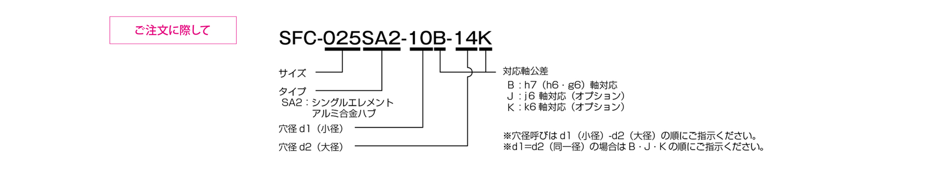
Taper Shaft Compatible: SFC-□DA2(BC)
By attaching a tapered adapter to the tapered shaft of the Servo motor, it can be locked using a clamping hub.
Specifications (Tapered Shaft)
| models | Shape TYPE | Permissible (operating) torque [N·m] | Permissible Tolerance | Max. rotation speed [min⁻¹] | Torsional Stiffness [N·m/rad] | Axial stiffness [N/mm] | Moment of inertia [kg·m²] | Mass [kg] | ||
|---|---|---|---|---|---|---|---|---|---|---|
| Eccentricity [mm] | Angular misalignment [°] | In the axial direction [mm] | ||||||||
| SFC-040DA2-□B-11BC | B | 12 | 0.24 | 1 (one side) | ±0.6 | 10,000 | 10,000 | 40 | 39.42×10⁻⁶ | 0.180 |
| C | 46.12×10⁻⁶ | 0.195 | ||||||||
| SFC-050DA2-□B-11BC | B | 25 | 0.28 | 1 (one side) | ±0.8 | 10,000 | 16,000 | 24 | 125.5 × 10⁻⁶ | 0.331 |
| C | 146.1×10⁻⁶ | 0.349 | ||||||||
| SFC-050DA2-□B-14BC | B | 25 | 0.28 | 1 (per side) | ±0.8 | 10,000 | 16,000 | 24 | 131.1 × 10⁻⁶ | 0.362 |
| C | 154.1×10⁻⁶ | 0.392 | ||||||||
| SFC-050DA2-□B-16BC | B | 25 | 0.28 | 1 (per side) | ±0.8 | 10,000 | 16,000 | 24 | 138.1 × 10⁻⁶ | 0.400 |
| C | 160.8×10⁻⁶ | 0.430 | ||||||||
| SFC-055DA2-□B-14BC | C | 40 | 0.31 | 1 (one side) | ±0.84 | 10,000 | 25,000 | 21.5 | 274.0 × 10⁻⁶ | 0.530 |
| SFC-055DA2-□B-16BC | C | 40 | 0.31 | 1 (one side) | ±0.84 | 10,000 | 25,000 | 21.5 | 280.5 × 10⁻⁶ | 0.567 |
| SFC-060DA2-□B-16BC | B | 60 | 0.34 | 1 (one side) | ±0.9 | 10,000 | 35,000 | 38.2 | 339.4 × 10⁻⁶ | 0.638 |
| C | 398.5×10⁻⁶ | 0.681 | ||||||||
- The TYPE (B/C) is automatically determined based on the combination of bore sizes you select, so you cannot specify it.
- The permissible (operating) torque may be limited by the Holding Power of the shaft fastening section, so please verify it using the standard bore size.
- The max. rotation speed does not take dynamic balance into account.
- The torsional stiffness values are based solely on measurements taken of the element section.
- The moment of inertia and mass are the values corresponding to the maximum bore size.
Dimensions (Tapered Shaft)

| models | d2 | W | T | WA | LA | dA | DA | LL | D | L | LF | C | A1 | A2 | M |
|---|---|---|---|---|---|---|---|---|---|---|---|---|---|---|---|
| Quantity-nominal size | |||||||||||||||
| SFC-040DA2-□B-11BC | 11 | 4 | 12.2 | 18 | 16 | 17 | 22 | 58 | 44 | 48 | 15.5 | 4.5 | 11 | 17 | 1-M4 |
| SFC-050DA2-□B-11BC | 11 | 4 | 12.2 | 18 | 16 | 17 | 22 | 64.8 | 56 | 59.8 | 20.5 | 6 | 14.5 | 22 | 1-M5 |
| SFC-050DA2-□B-14BC | 14 | 4 | 15.1 | 24 | 19 | 22 | 28 | 69.8 | 56 | 59.8 | 20.5 | 6 | 14.5 | 22 | 1-M5 |
| SFC-050DA2-□B-16BC | 16 | 5 | 17.3 | 24 | 29 | 26 | 30 | 79.8 | 56 | 59.8 | 20.5 | 6 | 14.5 | 22 | 1-M5 |
| SFC-055DA2-□B-14BC | 14 | 4 | 15.1 | 24 | 19 | 22 | 28 | 74.4 | 63 | 68.7 | 24 | 7.75 | ― | 23 | 1-M6 |
| SFC-055DA2-□B-16BC | 16 | 5 | 17.3 | 24 | 29 | 26 | 30 | 84.7 | 63 | 68.7 | 24 | 7.75 | ― | 23 | 1-M6 |
| SFC-060DA2-□B-16BC | 16 | 5 | 17.3 | 24 | 29 | 26 | 30 | 89.3 | 68 | 73.3 | 25.2 | 7.75 | 17.5 | 26.5 | 1-M6 |
- For dimensions other than those listed above, please refer to the dimensions for the Single Version SFC (SA2).
Standard Bore Size (Tapered Shaft)
| Standard (Optional) Bore Size d1 [mm] and Permissible (Operating) Torque [N·m] | ||||||||||||||||||||||
|---|---|---|---|---|---|---|---|---|---|---|---|---|---|---|---|---|---|---|---|---|---|---|
| Nominal Bore Size | 8 | 9 | 9.525 | 10 | 11 | 12 | 13 | 14 | 15 | 16 | 17 | 18 | 19 | 20 | 22 | 24 | 25 | 28 | 30 | 32 | 35 | |
| Shaft Tolerance h7 (h6, g6) | B | ● | ● | ● | ● | ● | ● | ● | ● | ● | ● | ● | ● | ● | ● | ● | ● | ● | ● | ● | ● | ● |
| Shaft Tolerance j6 (Optional) | J | ○ | ○ | ○ | ○ | |||||||||||||||||
| Shaft Tolerance k6 (Optional) | K | ○ | ○ | ○ | ○ | ○ | ○ | ○ | ○ | |||||||||||||
| SFC-040DA2-□B-11BC | 9 | ● | ● | ● | ● | ● | ● | ● | ● | ● | ● | ● | ● | |||||||||
| SFC-050DA2-□B-11BC | 18/20/22/22 | ● | ● | ● | ● | ● | ● | ● | ● | ● | ● | ● | ● | ● | ● | ● | ||||||
| SFC-050DA2-□B-14BC | 18/20/22/22 | ● | ● | ● | ● | ● | ● | ● | ● | ● | ● | ● | ● | ● | ||||||||
| SFC-050DA2-□B-16BC | 18/20/22/22 | ● | ● | ● | ● | ● | ● | ● | ● | ● | ● | ● | ● | ● | ||||||||
| SFC-055DA2-□B-14BC | 31/34/36/38 | ● | ● | ● | ● | ● | ● | ● | ● | ● | ● | ● | ● | |||||||||
| SFC-055DA2-□B-16BC | 31/34/36/38 | ● | ● | ● | ● | ● | ● | ● | ● | ● | ● | ● | ● | |||||||||
| SFC-060DA2-□B-16BC | 50/51 | ● | ● | ● | ● | ● | ● | ● | ● | ● | ● | ● | ● | ● | ● | |||||||
- The standard bore size for shaft tolerance h7 (h6·g6) is nominal B.
- For shaft tolerances j6 and k6: The J and K designations are optional and apply only to the bore sizes marked with a circle.
- The bore sizes indicated by the ● symbol and numerical values in the corresponding columns are standard bore sizes. For bore sizes not listed in the table above, we may be able to accommodate them on a case-by-case basis, so Contact Us.
- For holes with numerical values, the permissible (operating) torque is limited by the Holding Power at the shaft fastening section due to the small bore size. The numerical values indicate the permissible torque [N·m].

Keyway Machining Supported
If you choose to use a shaft with a key, we can perform Keyway Machining on the clamping hub upon request.
Dimensions (SFC SA2/DA2)

| Keyway width compliant with H9 standard | Keyway width compliant with JS9 standard | ||||||||||||||||||||||||||
|---|---|---|---|---|---|---|---|---|---|---|---|---|---|---|---|---|---|---|---|---|---|---|---|---|---|---|---|
| Nominal shaft diameter | Bore size d1 and d2 [mm] |
Keyway width W1, W2 [mm] |
Keyway height T1, T2 [mm] |
Nominal Shaft Diameter | Bore size d1, d2 [mm] |
Keyway width W1 and W2 [mm] |
Keyway height T1 and T2 [mm] |
Nominal shaft diameter | Bore size d1, d2 [mm] |
Keyway width W1 and W2 [mm] |
Keyway height T1 and T2 [mm] |
Nominal shaft diameter | Bore Size d1, d2 [mm] |
Keyway width W1 and W2 [mm] |
Keyway height T1 and T2 [mm] |
||||||||||||
| Shaft diameter | Shaft Tolerance | Shaft diameter | Shaft tolerance | Shaft diameter | Shaft Tolerance | Shaft diameter | Shaft Tolerance | ||||||||||||||||||||
| h7 | j6 | k6 | h7 | j6 | k6 | h7 | j6 | k6 | h7 | j6 | k6 | ||||||||||||||||
| 8 | BH | - | KH | 8 | 3 + 0.0250 | 9.4 + 0.30 | 20 | BH | - | - | 20 | 6 + 0.0300 | 22.8 + 0.30 | 8 | BJ | - | KJ | 8 | 3 ± 0.0125 | 9.4 + 0.30 | 20 | BJ | - | - | 20 | 6 ± 0.0150 | 22.8 + 0.30 |
| 9 | BH | - | KH | 9 | 3 + 0.0250 | 10.4 + 0.30 | 22 | BH | JH | KH | 22 | 6 + 0.0300 | 24.8 + 0.30 | 9 | BJ | - | KJ | 9 | 3 ± 0.0125 | 10.4 + 0.30 | 22 | BJ | JJ | KJ | 22 | 6 ± 0.0150 | 24.8 + 0.30 |
| 10 | BH | - | - | 10 | 3 + 0.0250 | 11.4 + 0.30 | 24 | BH | JH | KH | 24 | 8 + 0.0360 | 27.3 + 0.30 | 10 | BJ | - | - | 10 | 3 ± 0.0125 | 11.4 + 0.30 | 24 | BJ | JJ | KJ | 24 | 8 ± 0.0180 | 27.3 + 0.30 |
| 11 | BH | - | - | 11 | 4 + 0.0300 | 12.8 + 0.30 | 25 | BH | - | - | 25 | 8 + 0.0360 | 28.3 + 0.30 | 11 | BJ | - | - | 11 | 4 ± 0.0150 | 12.8 + 0.30 | 25 | BJ | - | - | 25 | 8 ± 0.0180 | 28.3 + 0.30 |
| 12 | BH | - | - | 12 | 4 + 0.0300 | 13.8 + 0.30 | 28 | BH | JH | - | 28 | 8 + 0.0360 | 31.3 + 0.30 | 12 | BJ | - | - | 12 | 4 ± 0.0150 | 13.8 + 0.30 | 28 | BJ | JJ | - | 28 | 8 ± 0.0180 | 31.3 + 0.30 |
| 13 | BH | - | - | 13 | 5 + 0.0300 | 15.3 + 0.30 | 30 | BH | - | - | 30 | 8 + 0.0360 | 33.3 + 0.30 | 13 | BJ | - | - | 13 | 5 ± 0.0150 | 15.3 + 0.30 | 30 | BJ | - | - | 30 | 8 ± 0.0180 | 33.3 + 0.30 |
| 14 | BH | - | KH | 14 | 5 + 0.0300 | 16.3 + 0.30 | 32 | BH | - | KH | 32 | 10 + 0.0360 | 35.3 + 0.30 | 14 | BJ | - | KJ | 14 | 5 ± 0.0150 | 16.3 + 0.30 | 32 | BJ | - | KJ | 32 | 10 ± 0.0180 | 35.3 + 0.30 |
| 15 | BH | - | - | 15 | 5 + 0.0300 | 17.3 + 0.30 | 35 | BH | - | - | 35 | 10 + 0.0360 | 38.3 + 0.30 | 15 | BJ | - | - | 15 | 5 ± 0.0150 | 17.3 + 0.30 | 35 | BJ | - | - | 35 | 10 ± 0.0180 | 38.3 + 0.30 |
| 16 | BH | - | KH | 16 | 5 + 0.0300 | 18.3 + 0.30 | 38 | BH | - | KH | 38 | 10 + 0.0360 | 41.3 + 0.30 | 16 | BJ | - | KJ | 16 | 5 ± 0.0150 | 18.3 + 0.30 | 38 | BJ | - | KJ | 38 | 10 ± 0.0180 | 41.3 + 0.30 |
| 17 | BH | - | - | 17 | 5 + 0.0300 | 19.3 + 0.30 | 40 | BH | - | - | 40 | 12 + 0.0430 | 43.3 + 0.30 | 17 | BJ | - | - | 17 | 5 ± 0.0150 | 19.3 + 0.30 | 40 | BJ | - | - | 40 | 12 ± 0.0215 | 43.3 + 0.30 |
| 18 | BH | - | - | 18 | 6 + 0.0300 | 20.8 + 0.30 | 42 | BH | - | - | 42 | 12 + 0.0430 | 45.3 + 0.30 | 18 | BJ | - | - | 18 | 6 ± 0.0150 | 20.8 + 0.30 | 42 | BJ | - | - | 42 | 12 ± 0.0215 | 45.3 + 0.30 |
| 19 | BH | - | KH | 19 | 6 + 0.0300 | 21.8 + 0.30 | 45 | BH | - | - | 45 | 14 + 0.0430 | 48.8 + 0.30 | 19 | BJ | JJ | KJ | 19 | 6 ± 0.0150 | 21.8 + 0.30 | 45 | BJ | - | - | 45 | 14 ± 0.0215 | 48.8 + 0.30 |
- We can accommodate specifications not listed in the table above. Contact Us for more information.
