SFC [L] Fixed-Length Type
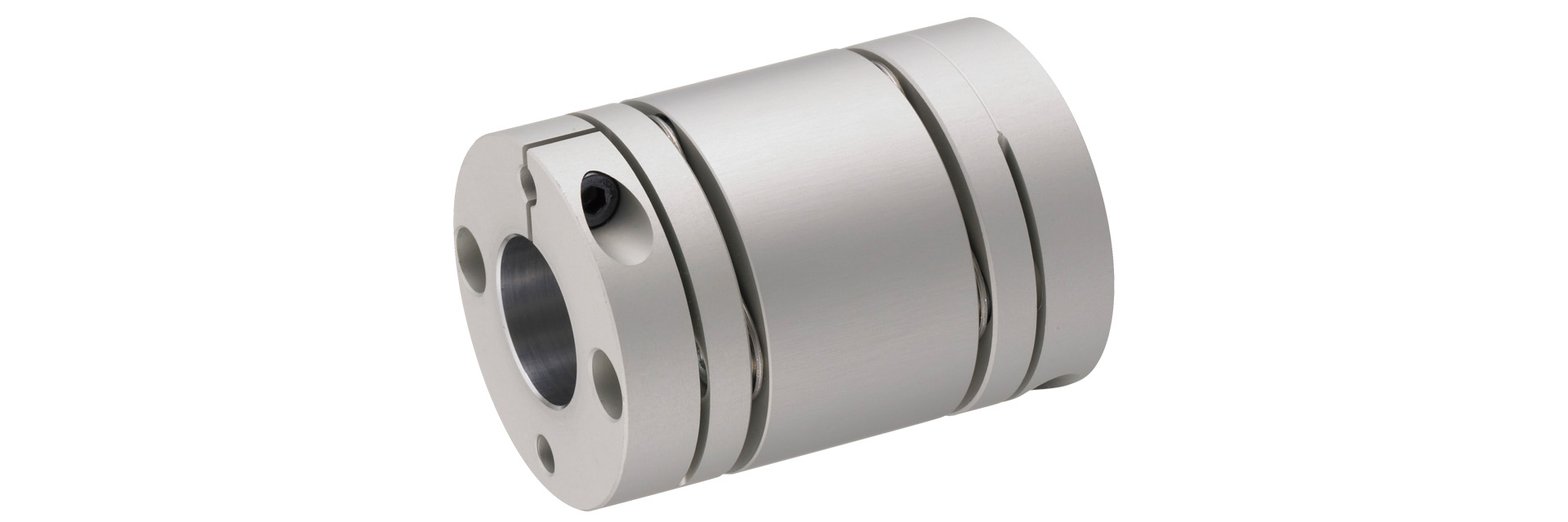
ダブルエレメントタイプの全長を対応範囲において1mm単位でご指定いただけます。中間に配置したスペーサの寸法を変更することで駆動-従動間に必要な寸法に対応します。また、スペーサ長さを変更することで、許容偏心量を大きくすることができ、よりフレキシブルな運転が可能です。
[Specifications]
| Model | Shape TYPE | Allowable Torque | Tolerance | Maximum Rotational Speed | Moment of Inertia | Mass | Price | |||||
|---|---|---|---|---|---|---|---|---|---|---|---|---|
| [N·m] | Eccentricity [mm] | Angular displacement | Axial | [min⁻¹] | [kg·m²] | [kg] | [yen] | |||||
| L min | L Max | [°] | [mm] | Min. L | Min. L | Min. L | Max. L | |||||
| SFC-005DA2 | C | 0.6 | 0.03 | 0.2 | 0.5 (per side) | ±0.1 | 10,000 | 0.33×10⁻⁶ | 0.62×10⁻⁶ | 0.009 | 0.017 | 8540 |
| SFC-010DA2 | C | 1 | 0.08 | 0.44 | 1 (per side) | ±0.2 | 10,000 | 0.72×10⁻⁶ | 1.38×10⁻⁶ | 0.014 | 0.026 | 7230 |
| SFC-020DA2 | C | 2 | 0.1 | 0.46 | 1 (per side) | ±0.33 | 10,000 | 3.02×10⁻⁶ | 5.30×10⁻⁶ | 0.031 | 0.054 | 8340 |
| SFC-025DA2 | C | 4 | 0.09 | 0.46 | 1 (per side) | ±0.38 | 10,000 | 4.55×10⁻⁶ | 7.95×10⁻⁶ | 0.036 | 0.061 | 8990 |
| SFC-030DA2 | A | 5 | 0.11 | 0.48 | 1 (per side) | ±0.4 | 10,000 | 6.09×10⁻⁶ | 12.80×10⁻⁶ | 0.046 | 0.085 | 9520 |
| B | 8.11×10⁻⁶ | 14.82×10⁻⁶ | 0.053 | 0.091 | ||||||||
| C | 10.22×10⁻⁶ | 16.93×10⁻⁶ | 0.061 | 0.099 | ||||||||
| SFC-035DA2 | C | 10 | 0.15 | 0.54 | 1 (per side) | ±0.5 | 10,000 | 23.85×10⁻⁶ | 35.97×10⁻⁶ | 0.108 | 0.161 | 11,020 |
| SFC-040DA2 | A | 12 | 0.15 | 0.54 | 1 (per side) | ±0.6 | 10,000 | 25.06×10⁻⁶ | 44.76×10⁻⁶ | 0.107 | 0.174 | 13,120 |
| B | 30.89×10⁻⁶ | 50.62×10⁻⁶ | 0.116 | 0.182 | ||||||||
| C | 37.58×10⁻⁶ | 57.31×10⁻⁶ | 0.13 | 0.197 | ||||||||
| SFC-050DA2 | A | 25 | 0.16 | 0.63 | 1 (per side) | ±0.8 | 10,000 | 77.42×10⁻⁶ | 144.3×10⁻⁶ | 0.205 | 0.347 | 16,120 |
| B | 97.97×10⁻⁶ | 164.8×10⁻⁶ | 0.225 | 0.365 | ||||||||
| C | 120.8×10⁻⁶ | 187.6×10⁻⁶ | 0.252 | 0.394 | ||||||||
| SFC-055DA2 | C | 40 | 0.16 | 0.6 | 1 (per side) | ±0.84 | 10,000 | 226.8×10⁻⁶ | 325.0×10⁻⁶ | 0.378 | 0.538 | 20,190 |
| SFC-060DA2 | A | 60 | 0.19 | 0.63 | 1 (per side) | ±0.9 | 10,000 | 210.8×10⁻⁶ | 340.1×10⁻⁶ | 0.382 | 0.567 | 23,690 |
| B | 269.9×10⁻⁶ | 399.2×10⁻⁶ | 0.424 | 0.609 | ||||||||
| C | 333.5×10⁻⁶ | 462.8×10⁻⁶ | 0.484 | 0.669 | ||||||||
- *Please note that the shape type (A, B, or C) is automatically determined based on the combination of hole diameters you select, so you cannot specify it.
- *Please note that the allowable torque may be limited by the holding force of the shaft fastening section; please verify this using the standard bore diameter of the SFC (DA2).
- *The maximum rotational speed does not take dynamic balance into account.
- *The moment of inertia and mass are based on the maximum bore diameter.
- *Please refer to the SFC(DA2) specifications for the values of each spring constant.
[Dimensions]
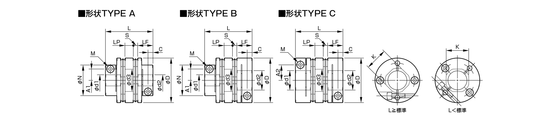
| Model | Shape TYPE | d1 | d2 | D | N | L | LF | S | A1 | A2 | C | d3 | K | M | Tightening torque | ||||
|---|---|---|---|---|---|---|---|---|---|---|---|---|---|---|---|---|---|---|---|
| Minimum | Max | Minimum | Max | Standard | Minimum | Max | [N·m] | ||||||||||||
| SFC-005DA2 | C | 3 | 6 | 3 | 6 | 16 | - | 23.2 | 21 | 40 | 7.85 | 1 | - | 4.8 | 2.5 | 6.5 | 6.5 | 1-M2 | 0.4–0.5 |
| SFC-010DA2 | C | 3 | 8 | 3 | 8 | 19 | - | 25.9 | 24 | 45 | 9.15 | 1.05 | - | 5.8(6) | 3.15 | 8.5 | 8.5 | 1–M2.5 (M2) | 1.0–1.1 (0.4–0.5) |
| SFC-020DA2 | C | 4 | 10 | 4 | 11 | 26 | - | 32.3 | 29 | 50 | 10.75 | 1.65 | - | 9.5 | 3.3 | 10.6 | 10.6 | 1-M2.5 | 1.0–1.1 |
| SFC-025DA2 | C | 5 | 14 | 5 | 14 | 29 | - | 32.8 | 29 | 50 | 10.75 | 1.9 | - | 11 | 3.3 | 15 | 14.5 | 1–M2.5 | 1.0–1.1 |
| SFC-030DA2 | A | 5 | 10 | 5 | 10 | 34 | 21.6 | 37.8 | 34 | 55 | 12.4 | 2.5 | 8 | - | 3.75 | 15 | 14.5 | 1-M3 | 1.5–1.9 |
| B | Over 10 | 16 | 12.5 | ||||||||||||||||
| C | Over 10 | 14 | - | - | |||||||||||||||
| SFC-035DA2 | C | 6 | 16 | 6 | 19 | 39 | - | 48 | 43 | 65 | 15.5 | 3 | - | 14 | 4.5 | 17 | 17 | 1-M4 | 3.4–4.1 |
| SFC-040DA2 | A | 8 | 15 | 8 | 15 | 44 | 29.6 | 48 | 43 | 65 | 15.5 | 3 | 11 | - | 4.5 | 20 | 19.5 | 1-M4 | 3.4–4.1 |
| B | Over 15 | 24 | 17 | ||||||||||||||||
| C | Over 15 | 19 | - | - | |||||||||||||||
| SFC-050DA2 | A | 8 | 19 | 8 | 19 | 56 | 38 | 59.8 | 53 | 80 | 20.5 | 2.4 | 14.5 | - | 6 | 26 | 26 | 1-M5 | 7.0–8.5 |
| B | Over 19 | 30 | 22 | ||||||||||||||||
| C | Over 19 | 25 | - | - | |||||||||||||||
| SFC-055DA2 | C | 10 | 30 | 10 | 30 | 63 | - | 68.7 | 60 | 85 | 24 | 2.6 | - | 23 | 7.75 | 31 | 31 | 1-M6 | 14–15 |
| SFC-060DA2 | A | 11 | 24 | 11 | 24 | 68 | 46 | 73.3 | 65 | 90 | 25.2 | 3.2 | 17.5 | - | 7.75 | 31 | 31 | 1-M6 | 14–15 |
| B | Over 24 | 35 | 26.5 | ||||||||||||||||
| C | Over 24 | 30 | - | - | |||||||||||||||
- *Please note that the shape type (A, B, or C) is automatically determined based on the combination of hole diameters you select, so you cannot specify it.
- *The designation for Clamp Bolt M is based on the quantity and thread size; the quantity refers to the number of bolts on one side of the hub.
- *The values in parentheses for SFC-010 apply when d1 or d2 is 8 mm.
- *The total length L that can be accommodated is the range from the minimum to the maximum L dimension shown in the table above. Please specify the length in 1-mm increments.
- *If the L dimension is shorter than the standard, the left and right clamp bolts will be offset by 45°.
- *Please refer to the standard bore diameter for SFC (DA2).