SFC [SA2] Type

This leaf spring-type coupling features a clamp hub made of lightweight, high-strength aluminum alloy, offering high torsional rigidity and excellent responsiveness. Additionally, the hub’s outer diameter is designed to match the shaft diameter, helping to reduce the moment of inertia. The SA2 type is a single-element, high-rigidity model.
[Specifications]
| Model | Rated Torque [N·m] |
Tolerance | Maximum Rotational Speed [min⁻¹] |
Torsional spring constant [N·m/rad] |
Axial spring constant [N/mm] |
Type |
Moment of Inertia [kg·m²] |
Mass [kg] |
Price [JPY] |
||
|---|---|---|---|---|---|---|---|---|---|---|---|
| Eccentricity [mm] |
Angular Deviation [°] |
Axial length [mm] |
|||||||||
| SFC-002SA2 | 0.25 | 0.01 | 0.5 | ±0.04 | 10,000 | 190 | 34 | C | 0.06×10⁻⁶ | 0.003 | |
| SFC-005SA2 | 0.6 | 0.02 | 0.5 | ±0.05 | 10,000 | 500 | 140 | C | 0.26×10⁻⁶ | 0.007 | |
| SFC-010SA2 | 1 | 0.02 | 1 | ±0.1 | 10,000 | 1400 | 140 | °C | 0.58×10⁻⁶ | 0.011 | |
| SFC-020SA2 | 2 | 0.02 | 1 | ±0.15 | 10,000 | 3,700 | 64 | °C | 2.39×10⁻⁶ | 0.025 | |
| SFC-025SA2 | 4 | 0.02 | 1 | ±0.19 | 10,000 | 5,600 | 60 | °C | 3.67×10⁻⁶ | 0.029 | |
| SFC-030SA2 | 5 | 0.02 | 1 | ±0.2 | 10,000 | 8,000 | 64 | A | 4.07×10⁻⁶ | 0.034 | |
| 5 | 0.02 | 1 | ±0.2 | 10,000 | 8,000 | 64 | B | 6.09×10⁻⁶ | 0.041 | ||
| 5 | 0.02 | 1 | ±0.2 | 10,000 | 8,000 | 64 | C | 8.20×10⁻⁶ | 0.049 | ||
| SFC-035SA2 | 10 | 0.02 | 1 | ±0.25 | 10,000 | 18,000 | 112 | °C | 18.44×10⁻⁶ | 0.082 | |
| SFC-040SA2 | 12 | 0.02 | 1 | ±0.3 | 10,000 | 20,000 | 80 | A | 16.71×10⁻⁶ | 0.077 | |
| 12 | 0.02 | 1 | ±0.3 | 10,000 | 20,000 | 80 | B | 22.55×10⁻⁶ | 0.085 | ||
| 12 | 0.02 | 1 | ±0.3 | 10,000 | 20,000 | 80 | °C | 29.25×10⁻⁶ | 0.100 | ||
| SFC-050SA2 | 25 | 0.02 | 1 | ±0.4 | 10,000 | 32,000 | 48 | A | 55.71×10⁻⁶ | 0.159 | |
| 25 | 0.02 | 1 | ±0.4 | 10,000 | 32,000 | 48 | B | 76.26×10⁻⁶ | 0.177 | ||
| 25 | 0.02 | 1 | ±0.4 | 10,000 | 32,000 | 48 | °C | 99.03×10⁻⁶ | 0.206 | ||
| SFC-055SA2 | 40 | 0.02 | 1 | ±0.42 | 10,000 | 50,000 | 43 | °C | 188.0×10⁻⁶ | 0.314 | |
| SFC-060SA2 | 60 | 0.02 | 1 | ±0.45 | 10,000 | 70,000 | 76.4 | A | 145.9×10⁻⁶ | 0.283 | |
| 60 | 0.02 | 1 | ±0.45 | 10,000 | 70,000 | 76.4 | B | 205.0×10⁻⁶ | 0.326 | ||
| 60 | 0.02 | 1 | ±0.45 | 10,000 | 70,000 | 76.4 | °C | 268.6×10⁻⁶ | 0.385 | ||
| SFC-080SA2 | 100 | 0.02 | 1 | ±0.55 | 10,000 | 140,000 | 128 | °C | 710.6×10⁻⁶ | 0.708 | |
| SFC-090SA2 | 180 | 0.02 | 1 | ±0.65 | 10,000 | 100,000 | 108 | C | 1236×10−6 | 0.946 | |
| SFC-100SA2 | 250 | 0.02 | 1 | ±0.74 | 10,000 | 120,000 | 111 | C | 1.891×10^(−6) | 1.202 | |
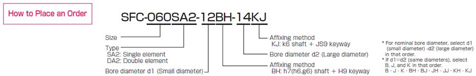
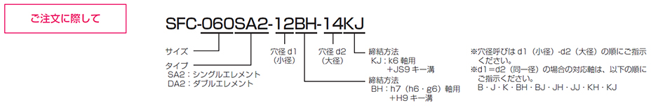
- The shape type (A, B, or C) is automatically determined based on the combination of hole diameters you select, so you cannot specify it.
- The allowable torque may be limited by the holding force of the shaft fastening section, so please verify it using the standard bore diameter.
- The maximum rotational speed does not take dynamic balance into account.
- The torsional spring constant values are based solely on measurements taken of the element section.
- The moment of inertia and mass are based on the maximum bore diameter.
[Dimensions]
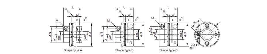
単位[mm]
| 型式 | d1 最小 |
d1 最大 |
d2 最小 |
d2 最大 |
D | DB | N | L | LF | S | A1 | A2 | C | K | M | 締め付けトルク [N・m] |
形状TYPE |
|---|---|---|---|---|---|---|---|---|---|---|---|---|---|---|---|---|---|
| SFC-002SA2 | 3 | 5 | 3 | 5 | 12 | 12.4 | ─ | 12.35 | 5.9 | 0.55 | ─ | 3.7 | 1.9 | 5.6 | 1-M1.6 | 0.23~0.28 | C |
| SFC-005SA2 | 3 | 6 | 3 | 6 | 16 | ─ | ─ | 16.7 | 7.85 | 1 | ─ | 4.8 | 2.5 | 6.5 | 1-M2 | 0.4~0.5 | C |
| SFC-010SA2 | 3 | 8 | 3 | 8 | 19 | ─ | ─ | 19.35 | 9.15 | 1.05 | ─ | 5.8(6) | 3.15 | 8.5 | 1-M2.5(M2) | 1.0~1.1(0.4~0.5) | C |
| SFC-020SA2 | 4 | 10 | 4 | 11 | 26 | ─ | ─ | 23.15 | 10.75 | 1.65 | ─ | 9.5 | 3.3 | 10.6 | 1-M2.5 | 1.0~1.1 | C |
| SFC-025SA2 | 5 | 14 | 5 | 14 | 29 | ─ | ─ | 23.4 | 10.75 | 1.9 | ─ | 11 | 3.3 | 14.5 | 1-M2.5 | 1.0~1.1 | C |
| SFC-030SA2 | 5 | 10 | 5 | 10 | 34 | ─ | 21.6 | 27.3 | 12.4 | 2.5 | 8 | ─ | 3.75 | 14.5 | 1-M3 | 1.5~1.9 | A |
| 5 | 10 | 10を超え | 16 | 34 | ─ | 21.6 | 27.3 | 12.4 | 2.5 | 8 | 12.5 | 3.75 | 14.5 | 1-M3 | 1.5~1.9 | B | |
| 10を超え | 14 | 10を超え | 16 | 34 | ─ | 21.6 | 27.3 | 12.4 | 2.5 | ─ | 12.5 | 3.75 | 14.5 | 1-M3 | 1.5~1.9 | C | |
| SFC-035SA2 | 6 | 16 | 6 | 19 | 39 | ─ | ─ | 34 | 15.5 | 3 | ─ | 14 | 4.5 | 17 | 1-M4 | 3.4~4.1 | C |
| SFC-040SA2 | 8 | 15 | 8 | 15 | 44 | ─ | 29.6 | 34 | 15.5 | 3 | 11 | ─ | 4.5 | 19.5 | 1-M4 | 3.4~4.1 | A |
| 8 | 15 | 15を超え | 24 | 44 | ─ | 29.6 | 34 | 15.5 | 3 | 11 | 17 | 4.5 | 19.5 | 1-M4 | 3.4~4.1 | B | |
| 15を超え | 19 | 15を超え | 24 | 44 | ─ | 29.6 | 34 | 15.5 | 3 | ─ | 17 | 4.5 | 19.5 | 1-M4 | 3.4~4.1 | C | |
| SFC-050SA2 | 8 | 19 | 8 | 19 | 56 | ─ | 38 | 43.4 | 20.5 | 2.4 | 14.5 | ─ | 6 | 26 | 1-M5 | 7.0~8.5 | A |
| 8 | 19 | 19を超え | 30 | 56 | ─ | 38 | 43.4 | 20.5 | 2.4 | 14.5 | 22 | 6 | 26 | 1-M5 | 7.0~8.5 | B | |
| 19を超え | 25 | 19を超え | 30 | 56 | ─ | 38 | 43.4 | 20.5 | 2.4 | ─ | 22 | 6 | 26 | 1-M5 | 7.0~8.5 | C | |
| SFC-055SA2 | 10 | 30 | 10 | 30 | 63 | ─ | ─ | 50.6 | 24 | 2.6 | ─ | 23 | 7.75 | 31 | 1-M6 | 14~15 | C |
| SFC-060SA2 | 11 | 24 | 11 | 24 | 68 | ─ | 46 | 53.6 | 25.2 | 3.2 | 17.5 | ─ | 7.75 | 31 | 1-M6 | 14~15 | A |
| 11 | 24 | 24を超え | 35 | 68 | ─ | 46 | 53.6 | 25.2 | 3.2 | 17.5 | 26.5 | 7.75 | 31 | 1-M6 | 14~15 | B | |
| 24を超え | 30 | 24を超え | 35 | 68 | ─ | 46 | 53.6 | 25.2 | 3.2 | ─ | 26.5 | 7.75 | 31 | 1-M6 | 14~15 | C | |
| SFC-080SA2 | 18 | 35 | 18 | 40 | 82 | ─ | ─ | 68 | 30 | 8 | ─ | 28 | 9 | 38 | 1-M8 | 27~30 | C |
| SFC-090SA2 | 25 | 40 | 25 | 45 | 94 | ─ | ─ | 68.3 | 30 | 8.3 | ─ | 34 | 9 | 42 | 1-M8 | 27~30 | C |
| SFC-100SA2 | 32 | 45 | 32 | 45 | 104 | ─ | ─ | 69.8 | 30 | 9.8 | ─ | 39 | 9 | 48 | 1-M8 | 27~30 | C |
- 形状 TYPE(A・B・C)はご採用いただく穴径の組み合わせにより自動的に決定いたしますのでご指示いただくことはできません。
- φDB寸法は、ハブ外径よりもクランプボルトの頭が出ている場合の寸法です。
- クランプボルトMの呼びは数量-ねじの呼びで、数量は片側ハブの数量です。
- SFC-010の( )内の数値は、d1またはd2がφ8mmの場合の値となります。
[Standard Hole Diameter]
| Standard (Optional) Bore Diameters d1 and d2 [mm] and Maximum Torque [N·m] | ||||||||||||||||||||||||||||||||
|---|---|---|---|---|---|---|---|---|---|---|---|---|---|---|---|---|---|---|---|---|---|---|---|---|---|---|---|---|---|---|---|---|
| Nominal Bore Diameter | 3 | 4 | 5 | 6 | 6.35 | 7 | 8 | 9 | 9.525 | 10 | 11 | 12 | 13 | 14 | 15 | 16 | 17 | 18 | 19 | 20 | 22 | 24 | 25 | 28 | 30 | 32 | 35 | 38 | 40 | 42 | 45 | |
| Shaft tolerance: h7 (h6, g6) | B | ● | ● | ● | ● | ● | ● | ● | ● | ● | ● | ● | ● | ● | ● | ● | ● | ● | ● | ● | ● | ● | ● | ● | ● | ● | ● | ● | ● | ● | ● | ● |
| Shaft tolerance: j6 (optional) | J | ○ | ○ | ○ | ○ | |||||||||||||||||||||||||||
| Shaft tolerance: k6 (optional) | K | ○ | ○ | ○ | ○ | ○ | ○ | ○ | ○ | ○ | ||||||||||||||||||||||
| SFC-002SA2 | d1 | ● | ● | ● | ||||||||||||||||||||||||||||
| d2 | ● | ● | ● | |||||||||||||||||||||||||||||
| SFC-005SA2 | d1 | ● | ● | ● | ● | |||||||||||||||||||||||||||
| d2 | ● | ● | ● | ● | ||||||||||||||||||||||||||||
| SFC-010SA2 | d1 | ● | ● | ● | ● | ● | ● | ● | ||||||||||||||||||||||||
| d2 | ● | ● | ● | ● | ● | ● | ● | |||||||||||||||||||||||||
| SFC-020SA2 | d1 | ● | ● | ● | ● | ● | ● | ● | ● | ● | ||||||||||||||||||||||
| d2 | ● | ● | ● | ● | ● | ● | ● | ● | ● | ● | ||||||||||||||||||||||
| SFC-025SA2 | d1 | 2.1 | ● | ● | ● | ● | ● | ● | ● | ● | ● | ● | ● | |||||||||||||||||||
| d2 | 2.1 | ● | ● | ● | ● | ● | ● | ● | ● | ● | ● | ● | ||||||||||||||||||||
| SFC-030SA2 | d1 | 2.8 | 3.4 | ● | ● | ● | ● | ● | ● | ● | ● | ● | ● | |||||||||||||||||||
| d2 | 2.8 | 3.4 | ● | ● | ● | ● | ● | ● | ● | ● | ● | ● | ● | ● | ||||||||||||||||||
| SFC-035SA2 | d1 | 5 | 5 | 6.6 | ● | ● | ● | ● | ● | ● | ● | ● | ● | ● | ||||||||||||||||||
| d2 | 5 | 5 | 6.6 | ● | ● | ● | ● | ● | ● | ● | ● | ● | ● | ● | ● | ● | ||||||||||||||||
| SFC-040SA2 | d1 | 9 | ● | ● | ● | ● | ● | ● | ● | ● | ● | ● | ● | ● | ||||||||||||||||||
| d2 | 9 | ● | ● | ● | ● | ● | ● | ● | ● | ● | ● | ● | ● | ● | ● | ● | ||||||||||||||||
| SFC-050SA2 | d1 | 18 | 20 | 22 | 22 | ● | ● | ● | ● | ● | ● | ● | ● | ● | ● | ● | ● | ● | ||||||||||||||
| d2 | 18 | 20 | 22 | 22 | ● | ● | ● | ● | ● | ● | ● | ● | ● | ● | ● | ● | ● | ● | ● | |||||||||||||
| SFC-055SA2 | d1 | 31 | 34 | 36 | 38 | ● | ● | ● | ● | ● | ● | ● | ● | ● | ● | ● | ● | |||||||||||||||
| d2 | 31 | 34 | 36 | 38 | ● | ● | ● | ● | ● | ● | ● | ● | ● | ● | ● | ● | ||||||||||||||||
| SFC-060SA2 | d1 | 50 | 51 | ● | ● | ● | ● | ● | ● | ● | ● | ● | ● | ● | ● | ● | ||||||||||||||||
| d2 | 50 | 51 | ● | ● | ● | ● | ● | ● | ● | ● | ● | ● | ● | ● | ● | ● | ● | |||||||||||||||
| SFC-080SA2 | d1 | ● | ● | ● | ● | ● | ● | ● | ● | ● | ● | |||||||||||||||||||||
| d2 | ● | ● | ● | ● | ● | ● | ● | ● | ● | ● | ● | ● | ||||||||||||||||||||
| SFC-090SA2 | d1 | ● | ● | ● | ● | ● | ● | ● | ||||||||||||||||||||||||
| d2 | ● | ● | ● | ● | ● | ● | ● | ● | ● | |||||||||||||||||||||||
| SFC-100SA2 | d1 | 226 | ● | ● | ● | ● | ● | |||||||||||||||||||||||||
| d2 | 226 | ● | ● | ● | ● | ● | ||||||||||||||||||||||||||
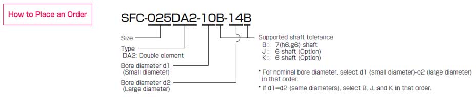
- The standard bore diameter for shaft tolerance h7 (h6/g6) is designation B. However, for a bore diameter of φ35, the shaft tolerance is +0.010 to -0.025.
- For shaft tolerances j6 and k6: The J and K designations are optional; only the hole diameters marked with a circle are supported.
- The hole diameters indicated by the ● symbol and numerical values in the corresponding columns are standard sizes. For hole diameters not listed in the table above, we may be able to accommodate special requests, so please contact us.
- Because the hole diameter in the column containing the numerical values is small, the allowable torque is limited by the holding force at the shaft fastening point. The numerical values indicate the allowable torque [N·m].
テーパ軸対応 SFC-□SA2(BC)
サーボモータのテーパ軸にテーパアダプターを取り付けることにより、クランプハブによる締結が可能となります。
For Tapered Shafts: SFC-□SA2(BC)
By attaching a tapered adapter to the tapered shaft of the servo motor, it can be secured using a clamping hub.
[Specifications]
| Model | Type | Rated Torque [N·m] |
Tolerance | Maximum Rotational Speed [min⁻¹] |
Torsional spring constant [N·m/rad] |
Axial spring constant [N/mm] |
Moment of inertia [kg·m²] |
Mass [kg] |
Price [JPY] |
||
|---|---|---|---|---|---|---|---|---|---|---|---|
| Eccentricity [mm] | Angular offset [°] | Axial [mm] | |||||||||
| SFC-040SA2-□B-11BC | B | 12 | 0.02 | 1 | ±0.3 | 10,000 | 20,000 | 80 | 26.58×10⁻⁶ | 0.131 | - |
| C | 12 | 0.02 | 1 | ±0.3 | 10,000 | 20,000 | 80 | 33.28×10⁻⁶ | 0.146 | - | |
| SFC-050SA2-□B-11BC | B | 25 | 0.02 | 1 | ±0.4 | 10,000 | 32,000 | 48 | 82.91×10⁻⁶ | 0.24 | - |
| C | 25 | 0.02 | 1 | ±0.4 | 10,000 | 32,000 | 48 | 103.5×10⁻⁶ | 0.258 | - | |
| SFC-050SA2-□B-14BC | B | 25 | 0.02 | 1 | ±0.4 | 10,000 | 32,000 | 48 | 88.72×10⁻⁶ | 0.271 | - |
| C | 25 | 0.02 | 1 | ±0.4 | 10,000 | 32,000 | 48 | 111.5×10⁻⁶ | 0.301 | - | |
| SFC-050SA2-□B-16BC | B | 25 | 0.02 | 1 | ±0.4 | 10,000 | 32,000 | 48 | 95.44×10^(−6) | 0.309 | - |
| C | 25 | 0.02 | 1 | ±0.4 | 10,000 | 32,000 | 48 | 118.2×10⁻⁶ | 0.338 | - | |
| SFC-055SA2-□B-14BC | C | 40 | 0.02 | 1 | ±0.42 | 10,000 | 50,000 | 43 | 201.1×10^(−6) | 0.409 | - |
| SFC-055SA2-□B-16BC | C | 40 | 0.02 | 1 | ±0.42 | 10,000 | 50,000 | 43 | 207.8×10⁻⁶ | 0.446 | - |
| SFC-060SA2-□B-16BC | B | 60 | 0.02 | 1 | ±0.45 | 10,000 | 70,000 | 76.4 | 228.7×10⁻⁶ | 0.475 | - |
| C | 60 | 0.02 | 1 | ±0.45 | 10,000 | 70,000 | 76.4 | 287.8×10⁻⁶ | 0.517 | - | |
- The TYPE (B or C) is automatically determined based on the combination of hole diameters you select, so you cannot specify it.
- The allowable torque may be limited by the holding force of the shaft fastening section, so please check the standard bore diameter.
- The maximum rotational speed does not take dynamic balance into account.
- The torsional spring constant values are based solely on measurements taken of the element section.
- The moment of inertia and mass are based on the maximum bore diameter.
[Dimensions]

Unit [mm]
| Model | d2 | W | T | WA | LA | dA | DA | LL | D | L | LF | C | A1 | A2 | M |
|---|---|---|---|---|---|---|---|---|---|---|---|---|---|---|---|
| Quantity-Nominal | |||||||||||||||
| SFC-040SA2-□B-11BC | 11 | 4 | 12.2 | 18 | 16 | 17 | 22 | 44 | 44 | 34 | 15.5 | 4.5 | 11 | 17 | 1-M4 |
| SFC-050SA2-□B-11BC | 11 | 4 | 12.2 | 18 | 16 | 17 | 22 | 48.4 | 56 | 43.4 | 20.5 | 6 | 14.5 | 22 | 1-M5 |
| SFC-050SA2-□B-14BC | 14 | 4 | 15.1 | 24 | 19 | 22 | 28 | 53.4 | 56 | 43.4 | 20.5 | 6 | 14.5 | 22 | 1-M5 |
| SFC-050SA2-□B-16BC | 16 | 5 | 17.3 | 24 | 29 | 26 | 30 | 63.4 | 56 | 43.4 | 20.5 | 6 | 14.5 | 22 | 1-M5 |
| SFC-055SA2-□B-14BC | 14 | 4 | 15.1 | 24 | 19 | 22 | 28 | 56.6 | 63 | 50.6 | 24 | 7.75 | ― | 23 | 1-M6 |
| SFC-055SA2-□B-16BC | 16 | 5 | 17.3 | 24 | 29 | 26 | 30 | 66.6 | 63 | 50.6 | 24 | 7.75 | ― | 23 | 1-M6 |
| SFC-060SA2-□B-16BC | 16 | 5 | 17.3 | 24 | 29 | 26 | 30 | 69.6 | 68 | 53.6 | 25.2 | 7.75 | 17.5 | 26.5 | 1-M6 |
- For dimensions other than those listed above, please refer to the dimensions for the Single Element Type SFC (SA2).
[Standard Hole Diameter]
| Standard (Optional) Hole Diameter d1 [mm] and Maximum Torque [N·m] | ||||||||||||||||||||||
|---|---|---|---|---|---|---|---|---|---|---|---|---|---|---|---|---|---|---|---|---|---|---|
| Nominal Hole Diameter | 8 | 9 | 9.525 | 10 | 11 | 12 | 13 | 14 | 15 | 16 | 17 | 18 | 19 | 20 | 22 | 24 | 25 | 28 | 30 | 32 | 35 | |
| Shaft tolerance h7 (h6, g6) | B | ● | ● | ● | ● | ● | ● | ● | ● | ● | ● | ● | ● | ● | ● | ● | ● | ● | ● | ● | ● | ● |
| Shaft tolerance j6 (optional) | J | ○ | ○ | ○ | ○ | |||||||||||||||||
| Shaft tolerance k6 (optional) | K | ○ | ○ | ○ | ○ | ○ | ○ | ○ | ○ | |||||||||||||
| SFC-040SA2-□B-11BC | 9 | ● | ● | ● | ● | ● | ● | ● | ● | ● | ● | ● | ● | |||||||||
| SFC-050SA2-□B-11BC | 18/20/22/22 | ● | ● | ● | ● | ● | ● | ● | ● | ● | ● | ● | ● | ● | ● | ● | ||||||
| SFC-050SA2-□B-14BC | 18/20/22/22 | ● | ● | ● | ● | ● | ● | ● | ● | ● | ● | ● | ● | ● | ||||||||
| SFC-050SA2-□B-16BC | 18/20/22/22 | ● | ● | ● | ● | ● | ● | ● | ● | ● | ● | ● | ● | ● | ||||||||
| SFC-055SA2-□B-14BC | 31/34/36/38 | ● | ● | ● | ● | ● | ● | ● | ● | ● | ● | ● | ● | ● | ||||||||
| SFC-055SA2-□B-16BC | 31/34/36/38 | ● | ● | ● | ● | ● | ● | ● | ● | ● | ● | ● | ● | ● | ||||||||
| SFC-060SA2-□B-16BC | 50/51 | ● | ● | ● | ● | ● | ● | ● | ● | ● | ● | ● | ● | ● | ● | ● | ||||||
- The standard bore diameter for shaft tolerance h7 (h6/g6) is nominal B.
- For shaft tolerances j6 and k6: The J and K designations are optional; only the hole diameters marked with a circle are supported.
- The hole diameters indicated by the ● symbol and numerical values in the corresponding columns are standard sizes. For hole diameters not listed in the table above, please contact us, as we may be able to accommodate special requests.
- Because the hole diameter in the column containing the numerical values is small, the allowable torque is limited by the holding force at the shaft fastening point. The numerical values indicate the allowable torque [N·m].

【寸法】(テーパ軸)

| 型式 | d2 | W | T | WA | LA | dA | DA | LL | D | L | LF | C | A1 | A2 | M |
|---|---|---|---|---|---|---|---|---|---|---|---|---|---|---|---|
| 数量-呼び | |||||||||||||||
| SFC-040SA2-□B-11BC | 11 | 4 | 12.2 | 18 | 16 | 17 | 22 | 44 | 44 | 34 | 15.5 | 4.5 | 11 | 17 | 1-M4 |
| SFC-050SA2-□B-11BC | 11 | 4 | 12.2 | 18 | 16 | 17 | 22 | 48.4 | 56 | 43.4 | 20.5 | 6 | 14.5 | 22 | 1-M5 |
| SFC-050SA2-□B-14BC | 14 | 4 | 15.1 | 24 | 19 | 22 | 28 | 53.4 | 56 | 43.4 | 20.5 | 6 | 14.5 | 22 | 1-M5 |
| SFC-050SA2-□B-16BC | 16 | 5 | 17.3 | 24 | 29 | 26 | 30 | 63.4 | 56 | 43.4 | 20.5 | 6 | 14.5 | 22 | 1-M5 |
| SFC-055SA2-□B-14BC | 14 | 4 | 15.1 | 24 | 19 | 22 | 28 | 56.6 | 63 | 50.6 | 24 | 7.75 | ― | 23 | 1-M6 |
| SFC-055SA2-□B-16BC | 16 | 5 | 17.3 | 24 | 29 | 26 | 30 | 66.6 | 63 | 50.6 | 24 | 7.75 | ― | 23 | 1-M6 |
| SFC-060SA2-□B-16BC | 16 | 5 | 17.3 | 24 | 29 | 26 | 30 | 69.6 | 68 | 53.6 | 25.2 | 7.75 | 17.5 | 26.5 | 1-M6 |
- 上記以外の寸法につきましては、シングルエレメントタイプ SFC(SA2)の寸法をご参照ください。
【標準穴径】(テーパ軸)
| 標準(オプション)穴径 d1[mm]と制限を受ける許容トルク[N・m] | ||||||||||||||||||||||
|---|---|---|---|---|---|---|---|---|---|---|---|---|---|---|---|---|---|---|---|---|---|---|
| 穴径呼び | 8 | 9 | 9.525 | 10 | 11 | 12 | 13 | 14 | 15 | 16 | 17 | 18 | 19 | 20 | 22 | 24 | 25 | 28 | 30 | 32 | 35 | |
| 軸公差 h7(h6・g6) | B | ● | ● | ● | ● | ● | ● | ● | ● | ● | ● | ● | ● | ● | ● | ● | ● | ● | ● | ● | ● | ● |
| 軸公差 j6(オプション) | J | ○ | ○ | ○ | ○ | |||||||||||||||||
| 軸公差 k6(オプション) | K | ○ | ○ | ○ | ○ | ○ | ○ | ○ | ○ | |||||||||||||
| SFC-040SA2-□B-11BC | 9 | ● | ● | ● | ● | ● | ● | ● | ● | ● | ● | ● | ● | |||||||||
| SFC-050SA2-□B-11BC | 18/20/22/22 | ● | ● | ● | ● | ● | ● | ● | ● | ● | ● | ● | ● | ● | ● | ● | ||||||
| SFC-050SA2-□B-14BC | 18/20/22/22 | ● | ● | ● | ● | ● | ● | ● | ● | ● | ● | ● | ● | ● | ||||||||
| SFC-050SA2-□B-16BC | 18/20/22/22 | ● | ● | ● | ● | ● | ● | ● | ● | ● | ● | ● | ● | ● | ||||||||
| SFC-055SA2-□B-14BC | 31/34/36/38 | ● | ● | ● | ● | ● | ● | ● | ● | ● | ● | ● | ● | ● | ||||||||
| SFC-055SA2-□B-16BC | 31/34/36/38 | ● | ● | ● | ● | ● | ● | ● | ● | ● | ● | ● | ● | ● | ||||||||
| SFC-060SA2-□B-16BC | 50/51 | ● | ● | ● | ● | ● | ● | ● | ● | ● | ● | ● | ● | ● | ● | ● | ||||||
- 標準穴径は、軸公差h7(h6・g6)用:呼びBとなります。
- 軸公差j6・k6用:呼びJ・Kはオプション対応となり、○印の穴径にみの対応となります。
- ●印と数値の入っている欄の穴径は標準穴径として対応しています。上表以外の穴径については、途別対応加納な場合がありますのでお問い合わせください。
- 数値の入っている欄の穴径は、その穴径が小さいため、軸締結部分での保持力によって許容トルクが制限を受けます。数値はその許容トルク[N・m]を示しています。

キー溝加工対応
キー付きの軸にご採用いただく場合、ご要望によりクランプハブにキー溝加工を施します。
Keyway machining supported
If you choose to use a keyed shaft, we can machine a keyway into the clamping hub upon request.
[Dimensions] SFC (SA2/DA2)
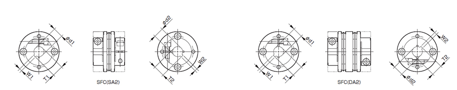
Unit [mm]
| Keyway Width H9 Standard Compatibility | Keyway Width: JS9 Standard | ||||||||||||||||||||||||||
|---|---|---|---|---|---|---|---|---|---|---|---|---|---|---|---|---|---|---|---|---|---|---|---|---|---|---|---|
| Nominal Shaft Diameter | Bore Diameter d1・d2 [mm] |
Keyway width W1, W2 [mm] |
Keyway depth T1 and T2 [mm] |
Nominal Shaft Diameter | Bore diameter d1, d2 [mm] |
Keyway width W1, W2 [mm] |
Keyway depth T1 and T2 [mm] |
Nominal shaft diameter | Bore diameter d1, d2 [mm] |
Keyway width W1, W2 [mm] |
Keyway depth T1 and T2 [mm] |
Nominal shaft diameter | Bore diameter d1, d2 [mm] |
Keyway width W1, W2 [mm] |
Keyway depth T1 and T2 [mm] |
||||||||||||
| Shaft diameter |
Shaft tolerance | Shaft diameter |
Shaft tolerance | Shaft diameter |
Shaft tolerance | Shaft diameter |
Shaft tolerance | ||||||||||||||||||||
| h7 | j6 | k6 | h7 | j6 | k6 | h7 | j6 | k6 | h7 | j6 | k6 | ||||||||||||||||
| 8 | BH | - | KH | 8 | 3+0.0250 | 9.4+0.30 | 20 | BH | - | - | 20 | 6+0.0300 | 22.8+0.30 | 8 | BJ | - | KJ | 8 | 3±0.0125 | 9.4+0.30 | 20 | BJ | - | - | 20 | 6±0.0150 | 22.8+0.30 |
| 9 | BH | - | KH | 9 | 3+0.0250 | 10.4+0.30 | 22 | BH | JH | KH | 22 | 6+0.0300 | 24.8+0.30 | 9 | BJ | - | KJ | 9 | 3±0.0125 | 10.4+0.30 | 22 | BJ | JJ | KJ | 22 | 6±0.0150 | 24.8+0.30 |
| 10 | BH | - | - | 10 | 3+0.0250 | 11.4+0.30 | 24 | BH | JH | KH | 24 | 8+0.0360 | 27.3+0.30 | 10 | BJ | - | - | 10 | 3±0.0125 | 11.4+0.30 | 24 | BJ | JJ | KJ | 24 | 8±0.0180 | 27.3+0.30 |
| 11 | BH | - | - | 11 | 4+0.0300 | 12.8+0.30 | 25 | BH | - | - | 25 | 8+0.0360 | 28.3+0.30 | 11 | BJ | - | - | 11 | 4±0.0150 | 12.8+0.30 | 25 | BJ | - | - | 25 | 8±0.0180 | 28.3+0.30 |
| 12 | BH | - | - | 12 | 4+0.0300 | 13.8+0.30 | 28 | BH | JH | - | 28 | 8+0.0360 | 31.3+0.30 | 12 | BJ | - | - | 12 | 4±0.0150 | 13.8+0.30 | 28 | BJ | JJ | - | 28 | 8±0.0180 | 31.3+0.30 |
| 13 | BH | - | - | 13 | 5+0.0300 | 15.3+0.30 | 30 | BH | - | - | 30 | 8+0.0360 | 33.3+0.30 | 13 | BJ | - | - | 13 | 5±0.0150 | 15.3+0.30 | 30 | BJ | - | - | 30 | 8±0.0180 | 33.3+0.30 |
| 14 | BH | - | KH | 14 | 5+0.0300 | 16.3+0.30 | 32 | BH | - | KH | 32 | 10+0.0360 | 35.3+0.30 | 14 | BJ | - | KJ | 14 | 5±0.0150 | 16.3+0.30 | 32 | BJ | - | KJ | 32 | 10±0.0180 | 35.3+0.30 |
| 15 | BH | - | - | 15 | 5+0.0300 | 17.3+0.30 | 35 | BH | - | - | 35 | 10+0.0360 | 38.3+0.30 | 15 | BJ | - | - | 15 | 5±0.0150 | 17.3+0.30 | 35 | BJ | - | - | 35 | 10±0.0180 | 38.3+0.30 |
| 16 | BH | - | KH | 16 | 5+0.0300 | 18.3+0.30 | 38 | BH | - | KH | 38 | 10+0.0360 | 41.3+0.30 | 16 | BJ | - | KJ | 16 | 5±0.0150 | 18.3+0.30 | 38 | BJ | - | KJ | 38 | 10±0.0180 | 41.3+0.30 |
| 17 | BH | - | - | 17 | 5+0.0300 | 19.3+0.30 | 40 | BH | - | - | 40 | 12+0.0430 | 43.3+0.30 | 17 | BJ | - | - | 17 | 5±0.0150 | 19.3+0.30 | 40 | BJ | - | - | 40 | 12±0.0215 | 43.3+0.30 |
| 18 | BH | - | - | 18 | 6+0.0300 | 20.8+0.30 | 42 | BH | - | - | 42 | 12+0.0430 | 45.3+0.30 | 18 | BJ | - | - | 18 | 6±0.0150 | 20.8+0.30 | 42 | BJ | - | - | 42 | 12±0.0215 | 45.3+0.30 |
| 19 | BH | - | KH | 19 | 6+0.0300 | 21.8+0.30 | 45 | BH | - | - | 45 | 14+0.0430 | 48.8+0.30 | 19 | BJ | JJ | KJ | 19 | 6±0.0150 | 21.8+0.30 | 45 | BJ | - | - | 45 | 14±0.0215 | 48.8+0.30 |
- We can accommodate specifications not listed in the table above. Please contact us.