SFH [G] Selectable Length Type
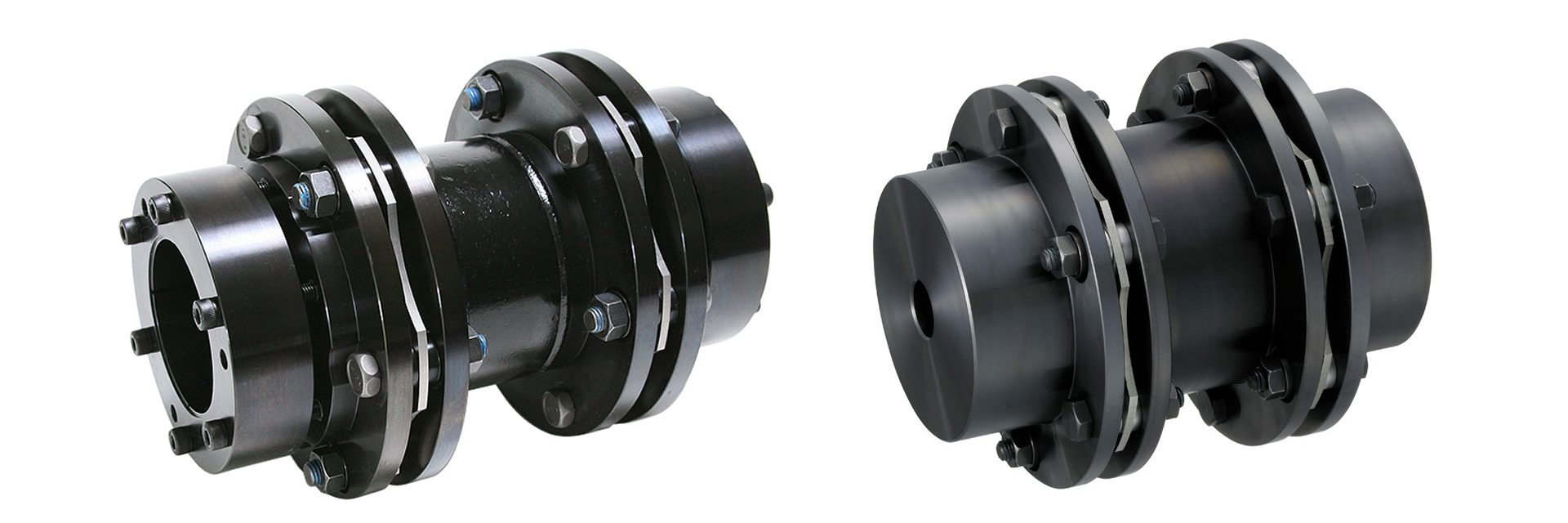
For high-output applications, our high-rigidity leaf spring couplings are available in sizes up to a flange outer diameter of 262 mm, with a maximum torque capacity of 8,000 N·m. The high-rigidity elements feature a proprietary hexagonal structure that enables high-precision power transmission for high-output servo motors. The fixed-length type features a flexible design with two sets of elements arranged via a floating shaft.
[Specifications] Wedge-type fastening
| Model | Rated Torque [N·m] |
Tolerance | Maximum Rotational Speed [min⁻¹] |
Torsional Spring Constant [N·m/rad] |
Axial spring constant [N/mm] |
Moment of inertia [kg·m²] |
Mass [kg] |
Price [JPY] |
||
|---|---|---|---|---|---|---|---|---|---|---|
| Eccentricity [mm] |
Angular offset [°] |
Axial length [mm] |
||||||||
| SFH-150G | 1000 | 1.4 | 1 (per side) | ±0.8 | 5900 | 750,000 | 122 | 34.41×10⁻³ | 12.96 | - |
| SFH-170G | 1300 | 1.6 | 1 (per side) | ±1.0 | 5100 | 1,420,000 | 112 | 72.09×10⁻³ | 18.95 | - |
| SFH-190G | 2000 | 2.0 | 1 (per side) | ±1.0 | 4700 | 1,700,000 | 122 | 98.15×10⁻³ | 23.14 | - |
| SFH-210G | 4,000 | 2.1 | 1 (per side) | ±1.1 | 4300 | 2,340,000 | 254 | 137.53×10⁻³ | 26.61 | - |
- The maximum rotational speed does not take dynamic balance into account.
- The moment of inertia and mass are based on the maximum bore diameter.
[Dimensions] Wedge-type fastening
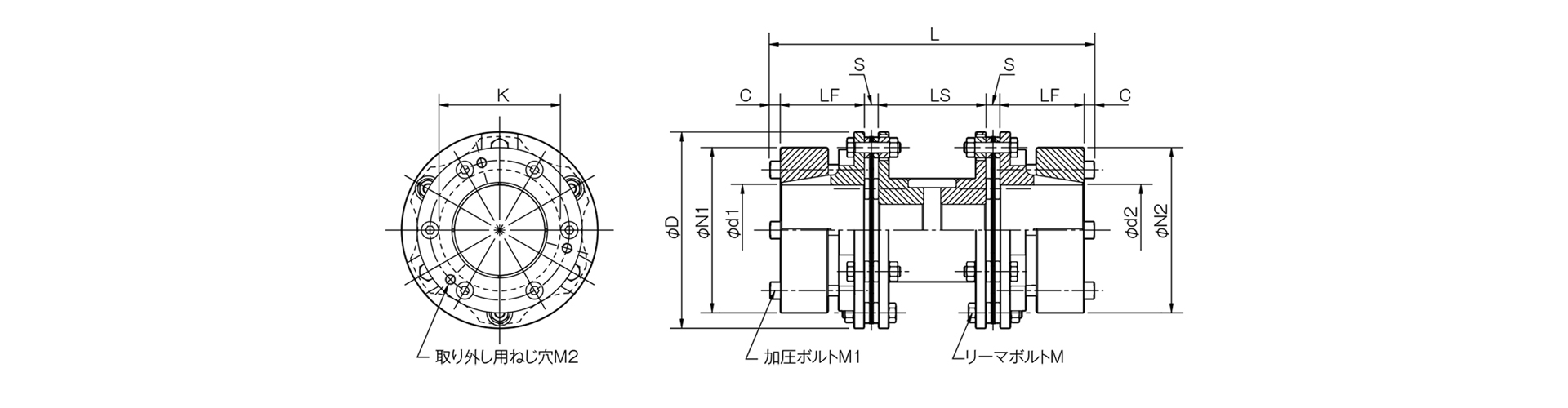
Unit [mm]
| Model | D | L | d1・d2 | N1・N2 | LF | LS | S | C | K | M | M1 | M2 |
|---|---|---|---|---|---|---|---|---|---|---|---|---|
| SFH-150G | 152 | 238 | 38, 40, 42, 45, 48, 50 | 108 | 65 | 70 | 11 | 8 | 94 | 12-M8×36 | 6-M8×60 | 3-M8 |
| 152 | 238 | 55, 56, 60, 65, 70 | 128 | 65 | 70 | 11 | 8 | 94 | 12-M8×36 | 6-M8×60 | 3-M8 | |
| SFH-170G | 178 | 254 | 38, 40, 42, 45, 48, 50 | 108 | 65 | 80 | 14 | 8 | 108 | 12-M10×45 | 6-M8×60 | 3-M8 |
| 178 | 254 | 55, 56, 60, 65, 70 | 128 | 65 | 80 | 14 | 8 | 108 | 12-M10×45 | 6-M8×60 | 3-M8 | |
| 178 | 254 | 75・80 | 148 | 65 | 80 | 14 | 8 | 108 | 12-M10×45 | 6-M8×60 | 3-M8 | |
| SFH-190G | 190 | 290 | 38, 40, 42, 45, 48, 50 | 108 | 70 | 100 | 15 | 10 | 116 | 12-M12×54 | 6-M10×65 | 3-M10 |
| 190 | 290 | 55, 56, 60, 65, 70 | 128 | 70 | 100 | 15 | 10 | 116 | 12-M12×54 | 6-M10×65 | 3-M10 | |
| 190 | 290 | 75, 80, 85 | 148 | 70 | 100 | 15 | 10 | 116 | 12-M12×54 | 6-M10×65 | 3-M10 | |
| SFH-210G | 210 | 306 | 38, 40, 42, 45, 48, 50 | 108 | 73 | 110 | 15 | 10 | 124 | 12-M16×60 | 6-M10×65 | 3-M10 |
| 210 | 306 | 55, 56, 60, 65, 70 | 128 | 73 | 110 | 15 | 10 | 124 | 12-M16×60 | 6-M10×65 | 3-M10 | |
| 210 | 306 | 75, 80, 85, 90 | 148 | 73 | 110 | 15 | 10 | 124 | 12-M16×60 | 6-M10×65 | 3-M10 |
- If you require a product that exceeds the LS dimensions listed above, please specify the required LS dimensions [mm]. Additionally, please contact us if the LS dimension is less than those listed above or if LS is 1000 or greater.
- The designation for each bolt and tap is calculated as "quantity × thread size × nominal length"; the quantities for the M1 pressure bolts and M2 removal screw holes refer to the number on one side of the flange.
[Standard Hole Diameter Combinations]
| Model | Standard Hole Diameter d1・d2 [mm] | ||||||||||||||
|---|---|---|---|---|---|---|---|---|---|---|---|---|---|---|---|
| 38 | 40 | 42 | 45 | 48 | 50 | 55 | 56 | 60 | 65 | 70 | 75 | 80 | 85 | 90 | |
| SFH-150G | ● | ● | ● | ● | ● | ● | ● | ● | ● | ● | ● | ||||
| SFH-170G | 1100 | 1200 | 1250 | ● | ● | ● | ● | ● | ● | ● | ● | ● | ● | ||
| SFH-190G | 1800 | 1900 | ● | ● | ● | ● | ● | ● | ● | ● | ● | ● | ● | ● | |
| SFH-210G | 1800 | 1900 | 2000 | 2150 | 2300 | 2400 | 2600 | 2650 | 2850 | 3100 | 3350 | 3600 | 3800 | ● | ● |
- The hole diameters indicated by the ● symbol and numerical values are standard hole diameters.
- Because the hole diameter in the column containing the numerical values is small, the allowable torque is limited by the holding force at the shaft fastening point. The numerical values indicate the allowable torque [N·m].

[Maximum LS Dimension for Vertical Use]
Unit [mm]
| Model | LS [mm] |
|---|---|
| SFH-150G | 1100 |
| SFH-170G | 800 |
| SFH-190G | 900 |
| SFH-210G | 2000 |
- If you are considering vertical installation and the LS dimension exceeds the values in the table above, please contact us.
[Specifications] Pilot hole / Key and set screw type
| Model | Rated Torque [N·m] | Tolerance | Maximum Rotational Speed [min−1] | Torsional Spring Constant [N·m/rad] | Axial spring constant [N/mm] | Moment of inertia [kg·m²] | Mass [kg] | Price of pre-drilled product [JPY] | ||
|---|---|---|---|---|---|---|---|---|---|---|
| Eccentricity [mm] | Angular offset [°] | Axial [mm] | ||||||||
| SFH-150G | 1000 | 1.4 | 1 (per side) | ±0.8 | 5900 | 750,000 | 122 | 21.87×10⁻³ | 8.72 | - |
| SFH-170G | 1,300 | 1.6 | 1 (per side) | ±1.0 | 5100 | 1,420,000 | 112 | 51.07×10⁻³ | 13.94 | - |
| SFH-190G | 2000 | 2 | 1 (per side) | ±1.0 | 4700 | 1,700,000 | 122 | 81.58×10⁻³ | 19.51 | - |
| SFH-210G | 4,000 | 2.1 | 1 (per side) | ±1.1 | 4300 | 2,340,000 | 254 | 125.50×10⁻³ | 24.26 | - |
| SFH-220G | 5000 | 2.3 | 1 (per side) | ±1.2 | 4000 | 2,970,000 | 224 | 176.91×10⁻³ | 30.27 | - |
| SFH-260G | 8000 | 2.9 | 1 (per side) | ±1.4 | 3,400 | 5,390,000 | 306 | 433.47×10⁻³ | 53.11 | - |
- The maximum rotational speed does not take dynamic balance into account.
- The moment of inertia and mass are based on the maximum bore diameter.
[Dimensions] Pilot hole / Key and set screw type
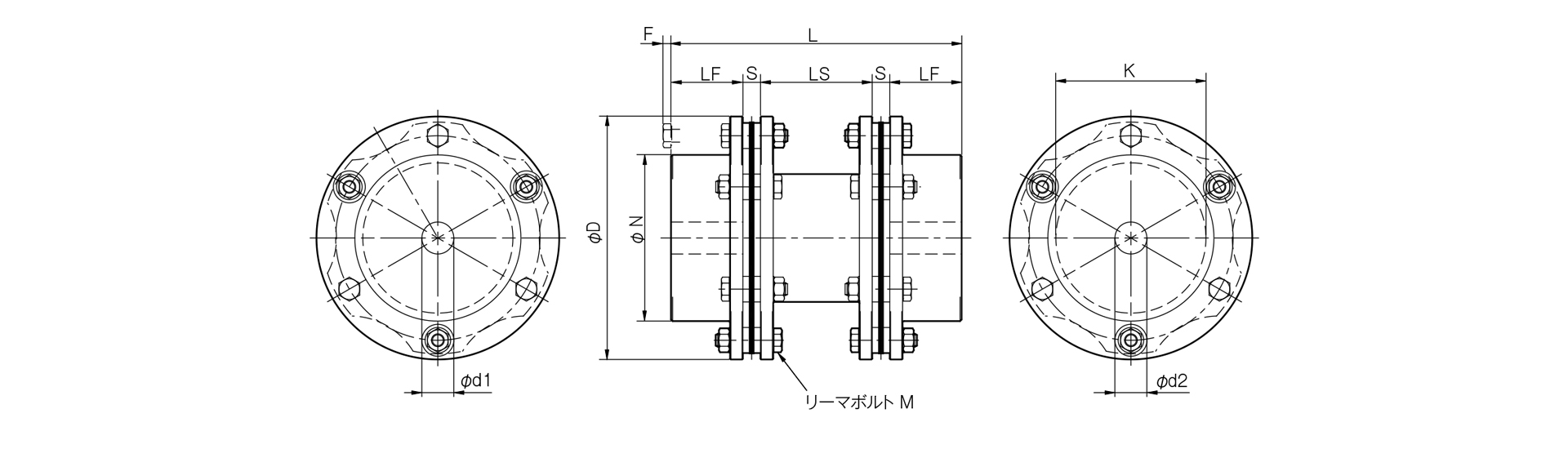
Unit [mm]
| Model | d1・d2 | D | N | L | LF | LS | S | F | K | M | CAD File No. | ||
|---|---|---|---|---|---|---|---|---|---|---|---|---|---|
| Pilot hole | Min. | Max | |||||||||||
| SFH-150G | 20 | 22 | 70 | 152 | 104 | 182 | 45 | 70 | 11 | 5 | 94 | 12-M8×36 | - |
| SFH-170G | 25 | 28 | 80 | 178 | 118 | 218 | 55 | 80 | 14 | 6 | 108 | 12-M10×45 | - |
| SFH-190G | 30 | 32 | 85 | 190 | 126 | 260 | 65 | 100 | 15 | 10 | 116 | 12-M12×54 | - |
| SFH-210G | 35 | 38 | 90 | 210 | 130 | 290 | 75 | 110 | 15 | 8 | 124 | 12-M16×60 | - |
| SFH-220G | 45 | 48 | 100 | 225 | 144 | 335 | 90 | 115 | 20 | -2 | 132 | 12-M16×60 | - |
| SFH-260G | 50 | 55 | 115 | 262 | 166 | 391 | 100 | 145 | 23 | 11 | 150 | 12-M20×80 | - |
- The pilot hole is a drill hole. For machined holes, please refer to the standard hole machining specifications.
- If you require a product with dimensions exceeding the LS dimensions listed above, please specify the required LS dimensions [mm]. Additionally, please contact us if the dimensions are less than those listed above or if LS is 1000 or greater.
- The price of a Reema Bolt M is calculated as: quantity × thread size × nominal length.

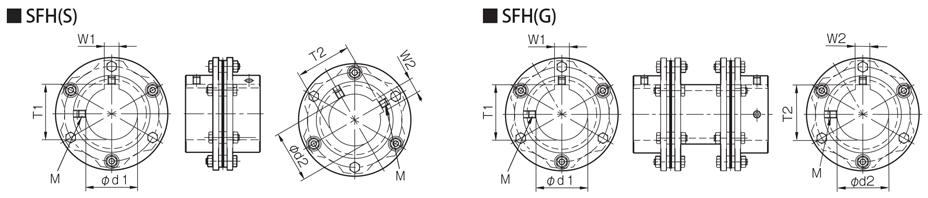
[Standard Hole Drilling Specifications]
| Compliant with JIS B 1301 1959 (Type 2, Old Standard) | Compliant with New JIS Standard H9 JIS B 1301 1996 | Motor Standard: Compliant with JIS C 4210 2001 | ||||||||||||
|---|---|---|---|---|---|---|---|---|---|---|---|---|---|---|
| Nominal Bore Diameter | Hole Diameter (d1, d2) |
Keyway width (W1, W2) |
Keyway depth (T1, T2) |
Set screw hole (M) |
Nominal hole diameter | Hole diameter (d1, d2) |
Keyway width (W1, W2) |
Keyway depth (T1, T2) |
Set screw hole (M) |
Nominal hole diameter | Hole diameter (d1, d2) |
Keyway width (W1, W2) |
Keyway depth (T1, T2) |
Set screw hole (M) |
| Tolerance H7 | Tolerance E9 | - | - | Tolerance H7 | Tolerance H9 | - | - | Tolerance G7, F7 | Tolerance H9 | - | - | |||
| 22 | 22+0.0210 | 7+0.061+0.025 | 25.0+0.30 | 2-M6 | 22H | 22+0.0210 | 6+0.0300 | 24.8+0.30 | 2-M5 | - | - | - | - | - |
| 24 | 24.8+0.0210 | 7+0.06 1+0.025 | 27.0+0.30 | 2-M6 | 24H | 24+0.0210 | 8+0.0360 | 27.3+0.30 | 2-M6 | 24N | 24+0.028+0.007 | 8+0.0360 | 27.3+0.30 | 2-M6 |
| 25 | 25+0.0210 | 7+0.061+0.025 | 28.0+0.30 | 2-M6 | 25H | 25+0.0210 | 8+0.0360 | 28.3+0.30 | 2-M6 | - | - | - | - | - |
| 28 | 28.3+0.0210 | 7+0.061+0.025 | 31.0+0.30 | 2-M6 | 28H | 28+0.0210 | 8+0.0360 | 31.3+0.30 | 2-M6 | 28N | 28+0.028+0.007 | 8+0.0360 | 31.3+0.30 | 2-M6 |
| 30 | 30+0.0210 | 7+0.061+0.025 | 33.0+0.30 | 2-M6 | 30H | 30+0.0210 | 8+0.0360 | 33.3+0.30 | 2-M6 | - | - | - | - | - |
| 32 | 32+0.0250 | 10+0.061+0.025 | 35.5+0.30 | 2-M8 | 32H | 32+0.0250 | 10+0.0360 | 35.3+0.30 | 2-M8 | - | - | - | - | - |
| 35 | 35.3+0.0250 | 10+0.061+0.025 | 38.5+0.30 | 2-M8 | 35H | 35+0.0250 | 10+0.0360 | 38.3+0.30 | 2-M8 | - | - | - | - | - |
| 38 | 38.3+0.0250 | 10+0.061+0.025 | 41.5+0.30 | 2-M8 | 38H | 38+0.0250 | 10+0.0360 | 41.3+0.30 | 2-M8 | 38N | 38+0.050+0.025 | 0.03601 | 41.3+0.30 | 2-M8 |
| 40 | 40+0.0250 | 10+0.061+0.025 | 43.5+0.30 | 2-M8 | 40H | 40+0.0250 | 12+0.0430 | 43.3+0.30 | 2-M8 | - | - | - | - | - |
| 42 | 42+0.0250 | 12+0.061+0.025 | 45.5+0.30 | 2-M8 | 42H | 42+0.0250 | 12+0.0430 | 45.3+0.30 | 2-M8 | 42N | 42+0.050+0.025 | 12+0.0430 | 45.3+0.30 | 2-M8 |
| 45 | 45.3+0.0250 | 12+0.061+0.025 | 48.5+0.30 | 2-M8 | 45H | 45+0.0250 | 14+0.0430 | 48.8+0.30 | 2-M10 | - | - | - | - | - |
| 48 | 48.8+0.0250 | 12+0.061+0.025 | 51.5+0.30 | 2-M8 | 48H | 48+0.0250 | 14+0.0430 | 51.8+0.30 | 2-M10 | 48N | 48+0.050+0.025 | 14+0.0430 | 51.8+0.30 | 2-M10 |
| 50 | 50+0.0250 | 12+0.061+0.025 | 53.5+0.30 | 2-M8 | 50H | 50+0.0250 | 14+0.0430 | 53.8+0.30 | 2-M10 | - | - | - | - | - |
| 55 | 55+0.0300 | 15+0.075+0.032 | 60.0+0.30 | 2-M10 | 55H | 55+0.0300 | 16+0.0430 | 59.3+0.30 | 2-M10 | 55N | 55+0.060+0.030 | 16+0.0430 | 59.3+0.30 | 2-M10 |
| 56 | 56+0.0300 | 15+0.075+0.032 | 61.0+0.30 | 2-M10 | 56H | 56+0.0300 | 16+0.0430 | 60.3+0.30 | 2-M10 | - | - | - | - | - |
| 60 | 60+0.0300 | 15+0.075+0.032 | 65.0+0.30 | 2-M10 | 60H | 60+0.0300 | 18+0.0430 | 64.4+0.30 | 2-M10 | 60N | 60+0.060+0.030 | 18+0.0430 | 64.4+0.30 | 2-M10 |
| 65 | 65+0.0300 | 18+0.075+0.032 | 71.0+0.30 | 2-M10 | 65H | 65+0.0300 | 18+0.0430 | 69.4+0.30 | 2-M10 | 65N | 65+0.060+0.030 | 18+0.0430 | 69.4+0.30 | 2-M10 |
| 70 | 70+0.0300 | 18+0.075+0.032 | 76.0+0.30 | 2-M10 | 70H | 70+0.0300 | 20+0.0520 | 74.9+0.50 | 2-M10 | - | - | - | - | - |
| 75 | 75+0.0300 | 20+0.092+0.040 | 81.0+0.50 | 2-M10 | 75H | 75+0.0300 | 20+0.0520 | 79.9+0.50 | 2-M10 | 75N | 75+0.060+0.030 | 20+0.0520 | 79.9+0.50 | 2-M10 |
| 80 | 80+0.0300 | 20+0.092+0.040 | 86.0+0.50 | 2-M10 | 80H | 80+0.0300 | 22+0.0520 | 85.4+0.50 | 2-M12 | - | - | - | - | - |
| 85 | 85+0.0350 | 24+0.092+0.040 | 93.0+0.50 | 2-M12 | 85H | 85+0.0350 | 22+0.0520 | 90.4+0.50 | 2-M12 | 85N | 85+0.071+0.035 | 22+0.0520 | 90.4+0.50 | 2-M12 |
| 90 | 90+0.0350 | 24+0.092+0.040 | 98.0+0.50 | 2-M12 | 90H | 90+0.0350 | 25+0.0520 | 95.4+0.50 | 2-M12 | - | - | - | - | - |
| 95 | 95+0.0350 | 24+0.092+0.040 | 103.0+0.50 | 2-M12 | 95H | 95+0.0350 | 25+0.0520 | 100.4+0.50 | 2-M12 | 95N | 95+0.071+0.035 | 25+0.0520 | 100.4+0.50 | 2-M12 |
| 100 | 100+0.0350 | 28+0.092+0.040 | 109.0+0.50 | 2-M12 | 100H | 100+0.0350 | 28+0.0520 | 106.4+0.50 | 2-M12 | - | - | - | - | - |
| 115 | 115+0.0350 | 32+0.11 2+0.050 | 125.0+0.50 | 2-M12 | 115H | 115+0.0350 | 32+0.0520 | 122.4+0.50 | 2-M12 | - | - | - | - | - |

[Maximum LS Dimension for Vertical Use]
Unit [mm]
| Model | LS [mm] |
|---|---|
| SFH-150G | 1100 |
| SFH-170G | 800 |
| SFH-190G | 900 |
| SFH-210G | 2000 |
| SFH-220G | 1900 |
| SFH-260G | 2500 |
- If you are considering vertical installation and the LS dimension exceeds the values in the table above, please contact us.