SFS [W] Type

This leaf spring coupling features a steel body and serves as the standard model in the Servoflex coupling series. The SFS model is supplied as a kit, allowing for flexible installation into equipment. It offers a variety of mounting options, including pilot holes, keyways, and friction-fit connections, while the W-type features a flexible double-element design.
[Specifications]
| Model | Rated Torque [N·m] | Tolerance | Maximum rotational speed [min⁻¹] | Torsional spring constant [N·m/rad] | Axial spring constant [N/mm] | Moment of inertia [kg·m²] | Mass [kg] | Price [JPY] | ||
|---|---|---|---|---|---|---|---|---|---|---|
| Eccentricity [mm] | Angular offset [°] | Axial length [mm] | ||||||||
| SFS-05W | 20 | 0.2 | 1 (per side) | ±1.2 | 10,000 | 8,000 | 21 | 0.14×10⁻³ | 0.40 | 28,510 |
| SFS-06W | 40 | 0.3 | 1 (per side) | ±1.6 | 8000 | 14,000 | 22 | 0.41×10⁻³ | 0.70 | 31,720 |
| SFS-08W | 80 | 0.3 | 1 (per side) | ±2.0 | 6800 | 41,000 | 30 | 1.10×10⁻³ | 1.30 | 36,330 |
| SFS-09W | 180 | 0.5 | 1 (per side) | ±2.4 | 6000 | 85,000 | 61 | 2.20×10⁻³ | 2.10 | 40,810 |
| SFS-10W | 250 | 0.5 | 1 (per side) | ±2.8 | 5200 | 125,000 | 80 | 3.60×10⁻³ | 2.80 | 45,280 |
| SFS-12W | 450 | 0.6 | 1 (per side) | ±3.2 | 4400 | 215,000 | 98 | 9.20×10⁻³ | 4.90 | 62,900 |
| SFS-14W | 800 | 0.7 | 1 (per side) | ±3.6 | 3800 | 390,000 | 156 | 15.00×10⁻³ | 7.10 | 83,020 |
- The maximum rotational speed does not take dynamic balance into account.
- The moment of inertia and mass are based on the maximum bore diameter.
[Dimensions]

Unit [mm]
| Model | d1・d2 | D | N | L | LF | LP | S | F | d3 | K | M | ||
|---|---|---|---|---|---|---|---|---|---|---|---|---|---|
| Pilot hole | Minimum | Max | |||||||||||
| SFS-05W | 7 | 8 | 20 | 56 | 32 | 58 | 20 | 8 | 5 | 4 | 20 | 24 | 8-M5×15 |
| SFS-06W | 7 | 8 | 25 | 68 | 40 | 74 | 25 | 12 | 6 | 3 | 24 | 30 | 8-M6×18 |
| SFS-08W | 10 | 11 | 35 | 82 | 54 | 84 | 30 | 12 | 6 | 2 | 28 | 38 | 8-M6×20 |
| SFS-09W | 10 | 11 | 38 | 94 | 58 | 98 | 30 | 22 | 8 | 12 | 32 | 42 | 8-M8×27 |
| SFS-10W | 15 | 16 | 42 | 104 | 68 | 110 | 35 | 20 | 10 | 7 | 34 | 48 | 8-M8×27 |
| SFS-12W | 18 | 19 | 50 | 126 | 78 | 127 | 40 | 25 | 11 | 10 | 40 | 54 | 8-M10×32 |
| SFS-14W | 20 | 22 | 60 | 144 | 88 | 144 | 45 | 30 | 12 | 15 | 46 | 61 | 8-M12×38 |
- The pilot hole is a drill hole. For machined holes, please refer to the standard hole machining specifications.
- The size of a Reema Bolt M is calculated as: quantity × thread size × nominal length.
[Standard Hole Diameter]
| Model | Standard Hole Diameter d1・d2 [mm] | |||||||||||||||||||||||||||
|---|---|---|---|---|---|---|---|---|---|---|---|---|---|---|---|---|---|---|---|---|---|---|---|---|---|---|---|---|
| 8 | 9 | 10 | 11 | 12 | 14 | 15 | 16 | 17 | 18 | 19 | 20 | 22 | 24 | 25 | 28 | 30 | 32 | 35 | 38 | 40 | 42 | 45 | 48 | 50 | 55 | 56 | 60 | |
| SFS-05W | ● | ● | ● | ● | ● | ● | ● | ● | ● | ● | ● | ● | ||||||||||||||||
| SFS-06W | ● | ● | ● | ● | ● | ● | ● | ● | ● | ● | ● | ● | ● | ● | ● | |||||||||||||
| SFS-08W | ● | ● | ● | ● | ● | ● | ● | ● | ● | ● | ● | ● | ● | ● | ● | ● | ||||||||||||
| SFS-09W | ● | ● | ● | ● | ● | ● | ● | ● | ● | ● | ● | ● | ● | ● | ● | ● | ● | |||||||||||
| SFS-10W | ● | ● | ● | ● | ● | ● | ● | ● | ● | ● | ● | ● | ● | ● | ● | |||||||||||||
| SFS-12W | ● | ● | ● | ● | ● | ● | ● | ● | ● | ● | ● | ● | ● | ● | ● | |||||||||||||
| SFS-14W | ● | ● | ● | ● | ● | ● | ● | ● | ● | ● | ● | ● | ● | ● | ● | ● | ||||||||||||
- The hole diameters indicated by the ● symbol are standard hole diameters. For details, please refer to the standard hole machining specifications.

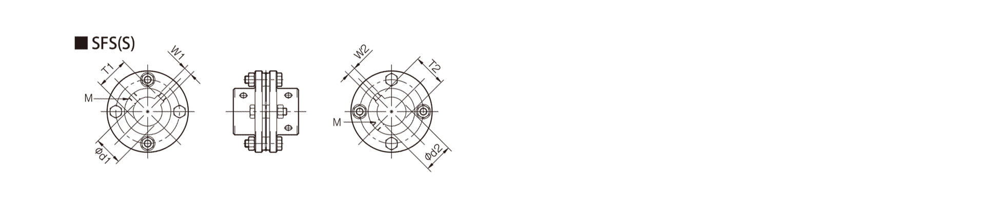
[Standard Hole Drilling Specifications]
Unit [mm]
| Compliant with JIS B 1301 1959 (Type 2, Old Standard) | Compliant with JIS New Standard H9 JIS B 1301 1996 | New JIS Standard JS9 (Compliant with JIS B 1301:1996) | ||||||||||||
|---|---|---|---|---|---|---|---|---|---|---|---|---|---|---|
| Nominal hole diameter | Hole Diameter (d1, d2) | Keyway width (W1, W2) | Keyway depth (T1, T2) | Set screw hole (M) | Nominal hole diameter | Hole diameter (d1, d2) | Keyway width (W1, W2) | Keyway depth (T1, T2) | Set screw hole (M) | Nominal hole diameter | Hole diameter (d1, d2) | Keyway width (W1, W2) | Keyway depth (T1, T2) | Set screw hole (M) |
| Nominal hole diameter | Tolerance H7, H8 | Tolerance E9 | - | - | Nominal hole diameter | Tolerance H7, H8 | Tolerance H9 | - | - | Nominal hole diameter | Tolerance H7, H8 | Tolerance JS9 | - | - |
| 8 | 8+0.0220 | - | - | 2-M4 | 8H | 8+0.0220 | 3 + 0.0250 | 9.4+0.30 | 2-M4 | 8J | 8 + 0.0220 | 3±0.0125 | 9.4+0.30 | 2-M4 |
| 9 | 9 + 0.0220 | - | - | 2-M4 | 9H | 9 + 0.0220 | 3 + 0.0250 | 10.4+0.30 | 2-M4 | 9J | 9 + 0.0220 | 3±0.0125 | 10.4+0.30 | 2-M4 |
| 10 | 10 + 0.0220 | - | - | 2-M4 | 10H | 10 + 0.0220 | 3 + 0.0250 | 11.4+0.30 | 2-M4 | 10J | 10 + 0.0220 | 3±0.0125 | 11.4+0.30 | 2-M4 |
| 11 | 11 + 0.0180 | - | - | 2-M4 | 11H | 11 + 0.0180 | 4 + 0.0300 | 12.8+0.30 | 2-M4 | 11J | 11 + 0.0180 | 4±0.0150 | 12.8+0.30 | 2-M4 |
| 12 | 12 + 0.0180 | 4+0.050+0.020 | 13.5+0.30 | 2-M4 | 12H | 12 + 0.0180 | 4 + 0.0300 | 13.8+0.30 | 2-M4 | 12J | 12 + 0.0180 | 4±0.0150 | 13.8+0.30 | 2-M4 |
| 14 | 14 + 0.0180 | 5+0.050+0.020 | 16+0.30 | 2-M4 | 14H | 14+0.0180 | 5 + 0.0300 | 16.3+0.30 | 2-M4 | 14J | 14 + 0.0180 | 5±0.0150 | 16.3+0.30 | 2-M4 |
| 15 | 15 + 0.0180 | 5+0.050+0.020 | 17+0.30 | 2-M4 | 15H | 15+0.0180 | 5+0.0300 | 17.3+0.30 | 2-M4 | 15J | 15 + 0.0180 | 5±0.0150 | 17.3+0.30 | 2-M4 |
| 16 | 16 + 0.0180 | 5+0.050+0.020 | 18+0.30 | 2-M4 | 16H | 16+0.0180 | 5 + 0.0300 | 18.3+0.30 | 2-M4 | 16J | 16 + 0.0180 | 5±0.0150 | 18.3+0.30 | 2-M4 |
| 17 | 17 + 0.0180 | 5+0.050+0.020 | 19+0.30 | 2-M4 | 17H | 17+0.0180 | 5+0.0300 | 19.3+0.30 | 2-M4 | 17J | 17 + 0.0180 | 5±0.0150 | 19.3+0.30 | 2-M4 |
| 18 | 18 + 0.0180 | 5+0.050+0.020 | 20+0.30 | 2-M4 | 18H | 18+0.0180 | 6 + 0.0300 | 20.8+0.30 | 2-M5 | 18J | 18 + 0.0180 | 6±0.0150 | 20.8+0.30 | 2-M5 |
| 19 | 19 + 0.0210 | 5+0.050+0.020 | 21+0.30 | 2-M4 | 19H | 19 + 0.0210 | 6 + 0.0300 | 21.8+0.30 | 2-M5 | 19J | 19 + 0.0210 | 6±0.0150 | 21.8+0.30 | 2-M5 |
| 20 | 20 + 0.0210 | 5+0.050+0.020 | 22+0.30 | 2-M4 | 20H | 20 + 0.0210 | 6 + 0.0300 | 22.8+0.30 | 2-M5 | 20J | 20 + 0.0210 | 6±0.0150 | 22.8+0.30 | 2-M5 |
| 22 | 22+0.0210 | 7+0.061+0.025 | 25+0.30 | 2-M6 | 22H | 22 + 0.0210 | 6 + 0.0300 | 24.8+0.30 | 2-M5 | 22J | 22 + 0.0210 | 6±0.0150 | 24.8+0.30 | 2-M5 |
| 24 | 24 + 0.0210 | 7+0.061+0.025 | 27+0.30 | 2-M6 | 24H | 24 + 0.0210 | 8 + 0.0360 | 27.3+0.30 | 2-M6 | 24J | 24 + 0.0210 | 8±0.0180 | 27.3+0.30 | 2-M6 |
| 25 | 25 + 0.0210 | 7+0.061+0.025 | 28+0.30 | 2-M6 | 25H | 25 + 0.0210 | 8 + 0.0360 | 28.3+0.30 | 2-M6 | 25J | 25 + 0.0210 | 8±0.0180 | 28.3+0.30 | 2-M6 |
| 28 | 28 + 0.0210 | 7+0.061+0.025 | 31+0.30 | 2-M6 | 28H | 28 + 0.0210 | 8 + 0.0360 | 31.3+0.30 | 2-M6 | 28J | 28 + 0.0210 | 8±0.0180 | 31.3+0.30 | 2-M6 |
| 30 | 30 + 0.0210 | 7+0.061+0.025 | 33+0.30 | 2-M6 | 30H | 30 + 0.0210 | 8 + 0.0360 | 33.3+0.30 | 2-M6 | 30J | 30 + 0.0210 | 8±0.0180 | 33.3+0.30 | 2-M6 |
| 32 | 32 + 0.0250 | 10+0.061+0.025 | 35.5+0.30 | 2-M8 | 32H | 32 + 0.0250 | 10 + 0.0360 | 35.3+0.30 | 2-M8 | 32J | 32 + 0.0250 | 10±0.0180 | 35.3+0.30 | 2-M8 |
| 35 | 35 + 0.0250 | 10+0.061+0.025 | 38.5+0.30 | 2-M8 | 35H | 35 + 0.0250 | 10 + 0.0360 | 38.3+0.30 | 2-M8 | 35J | 35 + 0.0250 | 10±0.0180 | 38.3+0.30 | 2-M8 |
| 38 | 38 + 0.0250 | 10+0.061+0.025 | 41.5+0.30 | 2-M8 | 38H | 38 + 0.0250 | 10 + 0.0360 | 41.3+0.30 | 2-M8 | 38J | 38 + 0.0250 | 10±0.0180 | 41.3+0.30 | 2-M8 |
| 40 | 40 + 0.0250 | 10+0.061+0.025 | 43.5+0.30 | 2-M8 | 40H | 40 + 0.0250 | 12 + 0.0430 | 43.3+0.30 | 2-M8 | 40J | 40 + 0.0250 | 12±0.0215 | 43.3+0.30 | 2-M8 |
| 42 | 42 + 0.0250 | 12+0.075+0.032 | 45.5+0.30 | 2-M8 | 42H | 42 + 0.0250 | 12 + 0.0430 | 45.3+0.30 | 2-M8 | 42J | 42 + 0.0250 | 12±0.0215 | 45.3+0.30 | 2-M8 |
| 45 | 45 + 0.0250 | 12+0.075+0.032 | 48.5+0.30 | 2-M8 | 45H | 45 + 0.0250 | 14 + 0.0430 | 48.8+0.30 | 2-M10 | 45J | 45 + 0.0250 | 14±0.0215 | 48.8+0.30 | 2-M10 |
| 48 | 48 + 0.0250 | 12+0.075+0.032 | 51.5+0.30 | 2-M8 | 48H | 48 + 0.0250 | 14 + 0.0430 | 51.8+0.30 | 2-M10 | 48J | 48 + 0.0250 | 14±0.0215 | 51.8+0.30 | 2-M10 |
| 50 | 50 + 0.0250 | 12+0.075+0.032 | 53.5+0.30 | 2-M8 | 50H | 50 + 0.0250 | 14 + 0.0430 | 53.8+0.30 | 2-M10 | 50J | 50 + 0.0250 | 14±0.0215 | 53.8+0.30 | 2-M10 |
| 55 | 55+0.0300 | 15+0.075+0.032 | 60+0.30 | 2-M10 | 55H | 55+0.0300 | 16 + 0.0430 | 59.3+0.30 | 2-M10 | 55J | 55 + 0.0300 | 16±0.0215 | 59.3+0.30 | 2-M10 |
| 56 | 56+0.0300 | 15+0.075+0.032 | 61+0.30 | 2-M10 | 56H | 56 + 0.0300 | 16 + 0.0430 | 60.3+0.30 | 2-M10 | 56J | 56 + 0.0300 | 16±0.0215 | 60.3+0.30 | 2-M10 |
| 60 | 60 + 0.0300 | 15+0.075+0.032 | 65+0.30 | 2-M10 | 60H | 60+0.0300 | 18 + 0.0430 | 64.4+0.30 | 2-M10 | 60J | 60 + 0.0300 | 18±0.0215 | 64.4+0.30 | 2-M10 |
- The set screw and the keyway will not be on the same plane.
- The set screw is included with the product.
- The positional accuracy of keyway machining is checked visually.
- Please contact us if you require positional accuracy for the keyway relative to each hub.
- For standard dimensions of hole sizes other than those listed here, please refer to the technical data at the end of this document.
【止めねじの位置】
| 型式 | 端面からの位置[mm] |
|---|---|
| SFS-05 | 7 |
| SFS-06 | 9 |
| SFS-08 | 10 |
| SFS-09 | 10 |
| SFS-10 | 12 |
| SFS-12 | 12 |
| SFS-14 | 15 |
テーパ軸対応 SFS-□W(C)
サーボモータのテーパ軸に対応します。
【仕様】(テーパ軸)
| 型式 | 許容トルク [N・m] | 許容誤差 | 最高回転速度 [min−1] | ねじりばね定数 [N・m/rad] | 軸方向ばね定数 [N/mm] | 慣性モーメント [kg・m2] | 質量 [kg] | ||
|---|---|---|---|---|---|---|---|---|---|
| 偏心 [mm] | 偏角 [°] | 軸方向 [mm] | |||||||
| SFS-06W-□M-11C | 40 | 0.3 | 1(片側) | ±1.6 | 5000 | 14000 | 22 | 0.40×10⁻³ | 0.80 |
| SFS-06W-□M-16C | 40 | 0.3 | 1(片側) | ±1.6 | 5000 | 14000 | 22 | 0.45×10⁻³ | 0.90 |
| SFS-08W-□M-16C | 80 | 0.3 | 1(片側) | ±2.0 | 5000 | 41000 | 30 | 1.07×10⁻³ | 1.50 |
| SFS-09W-□M-16C | 180 | 0.5 | 1(片側) | ±2.4 | 5000 | 85000 | 61 | 2.10×10⁻³ | 2.30 |
- 軸締結部分の保持力により許容トルクが制限を受ける場合があります。標準外の穴径で小さい穴径の場合はご確認ください。
- 最高回転速度は動バランスを考慮しておりません。
- 慣性モーメントおよび質量は、最大穴径時の値となります。
【寸法】(テーパ軸)
| 型式 | d2呼び | d1 | d2 | W +0.0300 |
T +0.30 |
d4 | J | D | N1 | N2 | L1 | L2 | L3 | LF1 | LF2 | LP | LS | S | C | d3 | K | MS | MW | MG | M1 | M2 |
|---|---|---|---|---|---|---|---|---|---|---|---|---|---|---|---|---|---|---|---|---|---|---|---|---|---|---|
| SFS-06 | 11C | 12・14・15 | 11 | 4 | 12.2 | 18 | 9 | 68 | 40 | 30 | 60.8 | 78.8 | 90.8 | 25 | 25 | 12 | 24 | 6 | 4.8 | 24 | 30 | 4-M6×25 | 8-M6×18 | 8-M6×25 | 4-M5 | 2-M5 |
| SFS-06 | 16C | 15 | 16 | 5 | 17.3 | 28 | 10 | 68 | 40 | 40 | 75.8 | 93.8 | 105.8 | 40 | 25 | 12 | 24 | 6 | 4.8 | 24 | 30 | 4-M6×25 | 8-M6×18 | 8-M6×25 | 4-M5 | 2-M5 |
| SFS-08 | 16C | 15・16・17・18・19・20・22 | 16 | 5 | 17.3 | 28 | 10 | 82 | 54 | 40 | 80.8 | 98.8 | 112.8 | 30 | 40 | 12 | 26 | 6 | 4.8 | 28 | 38 | 4-M6×29 | 8-M6×20 | 8-M6×29 | 4-M6 | 2-M6 |
| SFS-09 | 16C | 25・28 | 16 | 5 | 17.3 | 28 | 10 | 94 | 58 | 40 | 82.8 | 112.8 | 120.8 | 30 | 40 | 22 | 30 | 8 | 4.8 | 32 | 42 | 4-M8×36 | 8-M8×27 | 8-M8×36 | 6-M6 | 2-M6 |
| SFS-09 | 16C | 30・32・35 | 16 | 5 | 17.3 | 28 | 10 | 94 | 68 | 40 | 90.8 | 120.8 | 128.8 | 38 | 40 | 22 | 30 | 8 | 4.8 | 32 | 42 | 4-M8×36 | 8-M8×27 | 8-M8×36 | 6-M6 | 2-M6 |
- SFS(G) タイプにおいて、LS 寸法以外の製品をご要望の際は、必要LS 寸法をご指示ください。また、LS ≧1000 の際は、お問い合わせください。
- 各ボルト、タップの呼びは数量- ねじの呼び×呼び長さです。
- 摩擦締結側ハブの相手取り付け軸の寸法許容差はh7(h6・g6)級となります。
摩擦締結ハブ SFS-□W(C)
ハブに摩擦締結要素を内蔵することで、より高精度な取り付けが可能です。
【仕様】(摩擦締結)
| 型式 | 許容トルク [N・m] | 許容誤差 | 最高回転速度 [min−1] | ねじりばね定数 [N・m/rad] | 軸方向ばね定数 [N/mm] | 慣性モーメント [kg・m2] | 質量 [kg] | ||
|---|---|---|---|---|---|---|---|---|---|
| 偏心 [mm] | 偏角 [°] | 軸方向 [mm] | |||||||
| SFS-06W-□M-□M | 40 | 0.3 | 1(片側) | ±1.6 | 5000 | 14000 | 22 | 0.41×10⁻³ | 0.90 |
| SFS-08W-□M-□M | 80 | 0.3 | 1(片側) | ±2.0 | 5000 | 41000 | 30 | 1.16×10⁻³ | 1.60 |
| SFS-09W-□M-□M | 180 | 0.5 | 1(片側) | ±2.4 | 5000 | 85000 | 61 | 2.40×10⁻³ | 2.50 |
| SFS-10W-□M-□M | 250 | 0.5 | 1(片側) | ±2.8 | 5000 | 125000 | 80 | 3.70×10⁻³ | 3.00 |
| SFS-12W-□M-□M | 450 | 0.6 | 1(片側) | ±3.2 | 4400 | 215000 | 98 | 9.50×10⁻³ | 5.60 |
| SFS-14W-□M-□M | 580 | 0.7 | 1(片側) | ±3.6 | 3800 | 390000 | 156 | 19.11×10⁻³ | 8.60 |
- 軸締結部分の保持力により許容トルクが制限を受ける場合がありますので、標準穴径でご確認ください。
- 最高回転速度は動バランスを考慮しておりません。
- 慣性モーメントおよび質量は、最大穴径時の値となります。
【寸法】(摩擦締結)
| 型式 | d1 | d2 | D | N1 | N2 | L1 | L2 | L3 | LF1 | LF2 | LP | LS | S | C | d3 | K | MS | MW | MG | M1 | M2 |
|---|---|---|---|---|---|---|---|---|---|---|---|---|---|---|---|---|---|---|---|---|---|
| SFS-06 | 12・14・15 | 12・14・15 | 68 | 40 | 40 | 65.6 | 83.6 | 95.6 | 25 | 25 | 12 | 24 | 6 | 4.8 | 24 | 30 | 4-M6×25 | 8-M6×18 | 8-M6×25 | 4-M5 | 2-M5 |
| SFS-08 | 15・16・17・18・19・20・22 | 15・16・17・18・19・20・22 | 82 | 54 | 54 | 75.6 | 93.6 | 107.6 | 30 | 30 | 12 | 26 | 6 | 4.8 | 28 | 38 | 4-M6×29 | 8-M6×20 | 8-M6×29 | 4-M6 | 2-M6 |
| SFS-09 | 25・28 | 25・28 | 94 | 58 | 58 | 77.6 | 107.6 | 115.6 | 30 | 30 | 22 | 30 | 8 | 4.8 | 32 | 42 | 4-M8×36 | 8-M8×27 | 8-M8×36 | 6-M6 | 2-M6 |
| SFS-09 | 25・28 | 30・32・35 | 94 | 58 | 68 | 85.6 | 115.6 | 123.6 | 30 | 38 | 22 | 30 | 8 | 4.8 | 32 | 42 | 4-M8×36 | 8-M8×27 | 8-M8×36 | 6-M6 | 2-M6 |
| SFS-09 | 30・32・35 | 30・32・35 | 94 | 68 | 68 | 93.6 | 123.6 | 131.6 | 38 | 38 | 22 | 30 | 8 | 4.8 | 32 | 42 | 4-M8×36 | 8-M8×27 | 8-M8×36 | 6-M6 | 2-M6 |
| SFS-10 | 25・28・30・32・35 | 25・28・30・32・35 | 104 | 68 | 68 | 89.6 | 119.6 | 129.6 | 35 | 35 | 20 | 30 | 10 | 4.8 | 34 | 48 | 4-M8×36 | 8-M8×27 | 8-M8×36 | 6-M6 | 2-M6 |
| SFS-12 | 30・32・35 | 30・32・35 | 126 | 78 | 78 | 101.6 | 137.6 | 150.6 | 40 | 40 | 25 | 38 | 11 | 5.3 | 40 | 54 | 4-M10×45 | 8-M10×32 | 8-M10×45 | 4-M8 | 2-M8 |
| SFS-14 | 35 | 35 | 144 | 88 | 88 | 112.6 | 154.6 | 170.6 | 45 | 45 | 30 | 46 | 12 | 5.3 | 46 | 61 | 4-M12×54 | 8-M12×38 | 8-M12×54 | 6-M8 | 2-M8 |
- SFS(G) タイプにおいて、LS 寸法以外の製品をご要望の際は、必要LS 寸法をご指示ください。また、LS ≧1000 の際は、お問い合わせください。
- 各ボルト、タップの呼びは数量- ねじの呼び×呼び長さで、加圧ボルトM1と取り外し用ねじ穴M2 の数量は片側ハブの数量です。
【標準穴径】(摩擦締結)
| SFS-06 | 標準穴径 d2[mm] | |||||||||||||
|---|---|---|---|---|---|---|---|---|---|---|---|---|---|---|
| 標準穴径 d1[mm] | 12M | 14M | 15M | 16M | 17M | 18M | 19M | 20M | 22M | 25M | 28M | 30M | 32M | 35M |
| 12M | ● | ● | ● | |||||||||||
| 14M | ● | ● | ||||||||||||
| 15M | ● | |||||||||||||
| SFS-08 | 標準穴径 d2[mm] | |||||||||||||
|---|---|---|---|---|---|---|---|---|---|---|---|---|---|---|
| 標準穴径 d1[mm] | 12M | 14M | 15M | 16M | 17M | 18M | 19M | 20M | 22M | 25M | 28M | 30M | 32M | 35M |
| 15M | ● | ● | ● | ● | ● | ● | ● | |||||||
| 16M | ● | ● | ● | ● | ● | ● | ||||||||
| 17M | ● | ● | ● | ● | ● | |||||||||
| 18M | ● | ● | ● | ● | ||||||||||
| 19M | ● | ● | ● | |||||||||||
| 20M | ● | ● | ||||||||||||
| 22M | ● | |||||||||||||
| SFS-09 | 標準穴径 d2[mm] | |||||||||||||
|---|---|---|---|---|---|---|---|---|---|---|---|---|---|---|
| 標準穴径 d1[mm] | 12M | 14M | 15M | 16M | 17M | 18M | 19M | 20M | 22M | 25M | 28M | 30M | 32M | 35M |
| 25M | ● | ● | ● | ● | ● | |||||||||
| 28M | ● | ● | ● | ● | ||||||||||
| 30M | ● | ● | ● | |||||||||||
| 32M | ● | ● | ||||||||||||
| 35M | ● | |||||||||||||
| SFS-10 | 標準穴径 d2[mm] | |||||||||||||
|---|---|---|---|---|---|---|---|---|---|---|---|---|---|---|
| 標準穴径 d1[mm] | 12M | 14M | 15M | 16M | 17M | 18M | 19M | 20M | 22M | 25M | 28M | 30M | 32M | 35M |
| 25M | ● | ● | ● | ● | ● | |||||||||
| 28M | ● | ● | ● | ● | ||||||||||
| 30M | ● | ● | ● | |||||||||||
| 32M | ● | ● | ||||||||||||
| 35M | ● | |||||||||||||
| SFS-12 | 標準穴径 d2[mm] | |||||||||||||
|---|---|---|---|---|---|---|---|---|---|---|---|---|---|---|
| 標準穴径 d1[mm] | 12M | 14M | 15M | 16M | 17M | 18M | 19M | 20M | 22M | 25M | 28M | 30M | 32M | 35M |
| 30M | 380 | 380 | 380 | |||||||||||
| 32M | 400 | 400 | ||||||||||||
| 35M | ● | |||||||||||||
| SFS-14 | 標準穴径 d2[mm] | |||||||||||||
|---|---|---|---|---|---|---|---|---|---|---|---|---|---|---|
| 標準穴径 d1[mm] | 12M | 14M | 15M | 16M | 17M | 18M | 19M | 20M | 22M | 25M | 28M | 30M | 32M | 35M |
| 35M | ● | |||||||||||||
- ●印と数値の入っている欄の穴径は、標準として対応しています。上表以外の穴径については、別途対応可能な場合がありますのでお問い合わせください。
- 数値の入っている欄の穴径は、その穴径が小さいため、軸締結部分での保持力によって許容トルクが制限を受けます。数値はその許容トルク値[N・m]を示しています。
- 上表以外の穴径で、その穴径が小さい場合許容トルクが制限を受けることがありますのでご確認ください。
- 相手取り付け軸の寸法許容差はh(7 h6・g6)級となります。ただし、穴径φ35の場合の軸公差は+0.010、-0.025となります。