CF-A [OG] Custom Length, Low-Speed Rotation Type
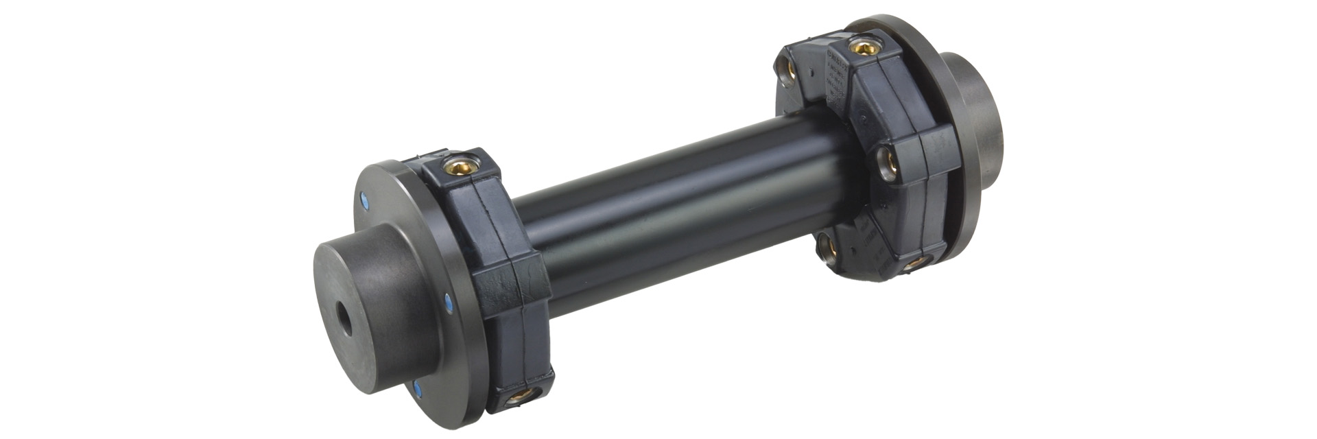
Power is transmitted via pre-compressed rubber. It excels at absorbing vibrations and shocks, and also reduces noise from machinery. The elastic rubber component consists of a polygonal rubber body with aluminum inserts embedded at its vertices.This type features two CF-A models clamping a floating shaft of adjustable total length, allowing for a wide tolerance range.
[Specifications]
| Model | Torque | Tolerance | Maximum Rotational Speed | Dynamic torsional spring constant | Moment of inertia | Mass | Price of pre-drilled products | ||||
|---|---|---|---|---|---|---|---|---|---|---|---|
| Standard | Maximum | Permissible Variation | Eccentricity | Angular Deviation | Axial | ||||||
| [N·m] | [N·m] | [N·m/10 Hz] | [mm] | [°] | [mm] | [min⁻¹] | [N·m/rad] | [kg·m²] | [kg] | [JPY] | |
| CF-A-001-OG-1360 | 10 | 25 | ±4 | 24.8 | 3 | ±2 | 1000 | 7.35×10¹ | 3.5×10⁻⁴ | 1.4 | |
| CF-A-002-OG-1360 | 20 | 50 | ±8 | 24.7 | 3 | ±3 | 1000 | 1.46×10² | 1.5×10⁻³ | 2.5 | |
| CF-A-004-OG-1360 | 40 | 100 | ±16 | 24.5 | 3 | ±3 | 1000 | 3.80×10² | 2.9×10⁻³ | 3.3 | |
| CF-A-008-OG-1360 | 80 | 200 | ±32 | 24.3 | 3 | ±4 | 1000 | 7.20×10² | 8.0×10⁻³ | 6.2 | |
| CF-A-012-OG-1360 | 120 | 300 | ±48 | 16.2 | 2 | ±4 | 1000 | 2.19×10³ | 8.4×10⁻³ | 6.4 | |
| CF-A-016-OG-1360 | 160 | 400 | ±64 | 23.7 | 3 | ±5 | 1000 | 1.64×10³ | 2.1×10⁻² | 10.6 | |
| CF-A-022-OG-1360 | 220 | 550 | ±88 | 15.8 | 2 | ±5 | 1000 | 4.13×10³ | 2.3×10⁻² | 11.0 | |
| CF-A-025-OG-1360 | 250 | 630 | ±100 | 23.5 | 3 | ±5 | 1000 | 2.06×10³ | 4.2×10⁻² | 15.9 | |
| CF-A-028-OG-1360 | 350 | 880 | ±140 | 15.6 | 2 | ±5 | 1000 | 0.53×10⁴ | 4.4×10⁻² | 16.5 | |
| CF-A-030-OG-1360 | 400 | 1000 | ±160 | 22.7 | 3 | ±5 | 1000 | 3.20×10³ | 9.6×10⁻² | 25.8 | |
| CF-A-050-OG-1360 | 600 | 1500 | ±240 | 15.2 | 2 | ±5 | 1000 | 7.40×10³ | 0.1 | 26.6 | |
| CF-A-080-OG-1360 | 800 | 2000 | ±320 | 15.1 | 2 | ±4 | 1000 | 1.09×10⁴ | 0.11 | 28.7 | |
| CF-A-090-OG-1360 | 900 | 2250 | ±360 | 22.1 | 3 | ±5 | 1000 | 6.85×10³ | 0.3 | 47.8 | |
| CF-A-140-OG-1360 | 1400 | 3500 | ±560 | 14.7 | 2 | ±5 | 1000 | 1.45×10⁴ | 0.31 | 49.3 | |
| CF-A-200-OG-1360 | 2000 | 5000 | ±800 | 14.4 | 2 | ±5 | 1000 | 3.04×10⁴ | 0.55 | 74.3 | |
| CF-A-250-OG-1360 | 3000 | 8750 | ±1250 | 14.2 | 2 | ±5 | 1000 | 4.14×10⁴ | 0.99 | 97.7 | |
| CF-A-400-OG-1360 | 5000 | 12,500 | ±2000 | 13.4 | 2 | ±5 | 1000 | 6.25×10⁴ | 1.77 | 164.6 | |
- The values in the table above apply to flange hubs with a bore diameter of L=500. (Prices remain the same for lengths up to L=600 mm.)
- The maximum rotational speed does not take dynamic balance into account.
- As a general rule, the dynamic torsional spring constant is approximately 1.3 times the static torsional spring constant.
[Dimensions]
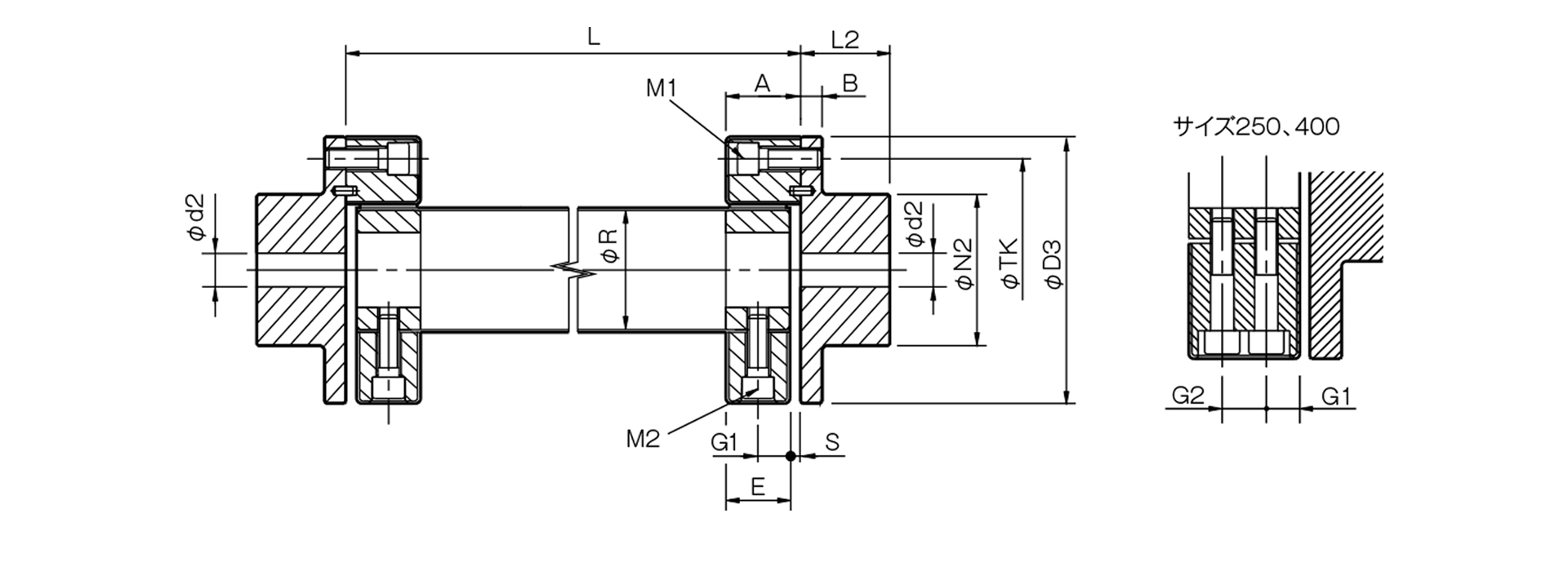
Unit [mm]
| Model | d2 | D3 | N2 | L2 | A | B | R | E | G1 | G2 | S | TK | M1 | M2 | ||
|---|---|---|---|---|---|---|---|---|---|---|---|---|---|---|---|---|
| Pilot hole | Minimum | Max | ||||||||||||||
| CF-A-001-OG-1360 | 8 | 9 | 22 | 56 | 36 | 24 | 24 | 7 | 30 | 22 | 11 | - | 2 | 44 | 2-M6 | 2-M6 |
| CF-A-002-OG-1360 | 9 | 10 | 30 | 85 | 45 | 28 | 24 | 8 | 40 | 20 | 10 | - | 4 | 68 | 2-M8 | 2-M8 |
| CF-A-004-OG-1360 | 11 | 12 | 36 | 100 | 55 | 30 | 28 | 8 | 45 | 24 | 12 | - | 4 | 80 | 3-M8 | 3-M8 |
| CF-A-008-OG-1360 | 15 | 16 | 46 | 120 | 70 | 42 | 32 | 10 | 60 | 28 | 14 | - | 4 | 100 | 3-M10 | 3-M10 |
| CF-A-012-OG-1360 | 15 | 16 | 46 | 120 | 70 | 42 | 32 | 10 | 60 | 28 | 14 | - | 4 | 100 | 4-M10 | 4-M10 |
| CF-A-016-OG-1360 | 19 | 20 | 56 | 150 | 85 | 50 | 42 | 12 | 70 | 36 | 18 | - | 6 | 125 | 3-M12 | 3-M12 |
| CF-A-022-OG-1360 | 19 | 20 | 56 | 150 | 85 | 50 | 42 | 12 | 70 | 36 | 18 | - | 6 | 125 | 4-M12 | 4-M12 |
| CF-A-025-OG-1360 | 19 | 20 | 65 | 170 | 100 | 56 | 46 | 14 | 85 | 40 | 20 | - | 6 | 140 | 3-M14 | 3-M14 |
| CF-A-028-OG-1360 | 19 | 20 | 65 | 170 | 100 | 56 | 46 | 14 | 85 | 40 | 20 | - | 6 | 140 | 4-M14 | 4-M14 |
| CF-A-030-OG-1360 | 28 | 30 | 80 | 200 | 120 | 66 | 58 | 16 | 100 | 50 | 25 | - | 8 | 165 | 3-M16 | 3-M16 |
| CF-A-050-OG-1360 | 28 | 30 | 80 | 200 | 120 | 66 | 58 | 16 | 100 | 50 | 25 | - | 8 | 165 | 4-M16 | 4-M16 |
| CF-A-080-OG-1360 | 28 | 30 | 80 | 200 | 120 | 66 | 65 | 16 | 100 | 61 | 30.5 | - | 4 | 165 | 4-M16 | 4-M16 |
| CF-A-090-OG-1360 | 30 | 32 | 95 | 260 | 140 | 80 | 70 | 19 | 125 | 62 | 31 | - | 8 | 215 | 3-M20 | 3-M20 |
| CF-A-140-OG-1360 | 30 | 32 | 95 | 260 | 140 | 80 | 70 | 19 | 125 | 62 | 31 | - | 8 | 215 | 4-M20 | 4-M20 |
| CF-A-200-OG-1360 | 35 | 38 | 110 | 300 | 160 | 90 | 80 | 19 | 145 | 72 | 36 | - | 8 | 250 | 4-M20 | 4-M20 |
| CF-A-250-OG-1360 | 40 | 42 | 120 | 340 | 180 | 100 | 85 | 19 | 160 | 77 | 22.5 | 32 | 8 | 280 | 4-M20 | 8-M20 |
| CF-A-400-OG-1360 | 40 | 42 | 130 | 370 | 200 | 125 | 105 | 29 | 170 | 95 | 28.5 | 38 | 10 | 300 | 4-M24 | 8-M20 |
- The pilot hole is a drill hole. The minimum values for d1 and d2 indicate the minimum hole diameters specified in our standard hole machining specifications, while the maximum values indicate the largest hole diameters that can be machined.
- The designation for M1 and M2 bolts consists of the quantity followed by the thread size; the quantity refers to the number of bolts on one side.
- The L dimension must be 1000 mm or less. Additionally, the minimum L dimension must allow sufficient space for the installation of an M1 bolt.
[Standard Hole Drilling Specifications]

Unit [mm]
| Compliant with JIS B 1301 1959 (Type 2) |
Compliant with New JIS Standard H9 JIS B 1301 1996 |
Motor Standard JIS C 4210 2001 |
||||||||||||
|---|---|---|---|---|---|---|---|---|---|---|---|---|---|---|
| Nominal Bore Diameter | Bore Diameter (d1, d2) |
Keyway width (W1, W2) |
Keyway depth (T1, T2) |
Set screw hole (M) |
Nominal hole diameter | Hole diameter (d1, d2) |
Keyway width (W1, W2) |
Keyway depth (T1, T2) |
Set screw hole (M) |
Nominal hole diameter | Hole diameter (d1, d2) |
Keyway width (W1, W2) |
Keyway depth (T1, T2) |
Set screw hole (M) |
| Nominal hole diameter | Tolerance H7, H8 | Tolerance E9 | - | ― | Nominal hole diameter | Tolerance H7 | Tolerance H9 | ― | - | Nominal hole diameter | Tolerance G7, F7 | Tolerance H9 | ― | - |
| 9 | 9+0.0220 | - | - | 2-M4 | - | - | - | - | - | - | - | - | - | - |
| 10 | 10+0.0220 | - | - | 2-M4 | - | - | - | - | - | - | - | - | - | - |
| 11 | 11 + 0.0180 | - | - | 2-M4 | - | - | - | - | - | - | - | - | - | - |
| 12 | 12 + 0.0180 | 4 + 0.05 + 0.02 | 13.5 + 0.30 | 2-M4 | 12H | 12 + 0.0180 | 4 + 0.030 | 13.8 + 0.30 | 2-M4 | - | - | - | - | - |
| 14 | 14 + 0.0180 | 5 + 0.05 + 0.02 | 16.0 + 0.30 | 2-M4 | 14H | 14 + 0.0180 | 5 + 0.030 | 16.3 + 0.30 | 2-M4 | 14N | 14 + 0.024 + 0.006 | 5 + 0.030 | 16.3 + 0.30 | 2-M4 |
| 15 | 15 + 0.0180 | 5 + 0.05 + 0.02 | 17.0 + 0.30 | 2-M4 | 15H | 15 + 0.0180 | 5 + 0.030 | 17.3 + 0.30 | 2-M4 | - | - | - | - | - |
| 16 | 16 + 0.0180 | 5 + 0.05 + 0.02 | 18.0 + 0.30 | 2-M4 | 16H | 16 + 0.0180 | 5 + 0.030 | 18.3 + 0.30 | 2-M4 | - | - | - | - | - |
| 17 | 17 + 0.0180 | 5 + 0.05 + 0.02 | 19.0 + 0.30 | 2-M4 | 17H | 17 + 0.0180 | 5 + 0.030 | 19.3 + 0.30 | 2-M4 | - | - | - | - | - |
| 18 | 18 + 0.0180 | 5 + 0.05 + 0.02 | 20.0 + 0.30 | 2-M4 | 18H | 18 + 0.0180 | 6 + 0.030 | 20.8 + 0.30 | 2-M5 | - | - | - | - | - |
| 19 | 19 + 0.0210 | 5 + 0.05 + 0.02 | 21.0 + 0.30 | 2-M4 | 19H | 19 + 0.0210 | 6 + 0.030 | 21.8 + 0.30 | 2-M5 | 19N | 19 + 0.028 + 0.007 | 6 + 0.030 | 21.8 + 0.30 | 2-M5 |
| 20 | 20 + 0.0210 | 5 + 0.05 + 0.02 | 22.0 + 0.30 | 2-M4 | 20H | 20 + 0.0210 | 6 + 0.030 | 22.8 + 0.30 | 2-M5 | - | - | - | - | - |
| 22 | 22 + 0.0210 | 7 + 0.061 + 0.025 | 25.0 + 0.30 | 2-M6 | 22H | 22 + 0.0210 | 6 + 0.030 | 24.8 + 0.30 | 2-M5 | - | - | - | - | - |
| 24 | 24 + 0.0210 | 7 + 0.061 + 0.025 | 27.0 + 0.30 | 2-M6 | 24H | 24 + 0.0210 | 8 + 0.0360 | 27.3 + 0.30 | 2-M6 | 24N | 24 + 0.028 + 0.007 | 8 + 0.0360 | 27.3 + 0.30 | 2-M6 |
| 25 | 25 + 0.0210 | 7 + 0.061 + 0.025 | 28.0 + 0.30 | 2-M6 | 25H | 25 + 0.0210 | 8 + 0.0360 | 28.3 + 0.30 | 2-M6 | - | - | - | - | - |
| 28 | 28 + 0.0210 | 7 + 0.061 + 0.025 | 31.0 + 0.30 | 2-M6 | 28H | 28 + 0.0210 | 8 + 0.0360 | 31.3 + 0.30 | 2-M6 | 28N | 28 + 0.02 8 + 0.007 | 8 + 0.0360 | 31.3 + 0.30 | 2-M6 |
| 30 | 30 + 0.0210 | 7 + 0.061 + 0.025 | 33.0 + 0.30 | 2-M6 | 30H | 30 + 0.0210 | 8 + 0.0360 | 33.3 + 0.30 | 2-M6 | - | - | - | - | - |
| 32 | 32 + 0.0250 | 10 + 0.06 1 + 0.025 | 35.5 + 0.30 | 2-M8 | 32H | 32 + 0.0250 | 10 + 0.0360 | 35.3 + 0.30 | 2-M8 | - | - | - | - | - |
| 35 | 35 + 0.0250 | 10 + 0.06 1 + 0.025 | 38.5 + 0.30 | 2-M8 | 35H | 35 + 0.0250 | 10 + 0.0360 | 38.3 + 0.30 | 2-M8 | - | - | - | - | - |
| 38 | 38 + 0.0250 | 10 + 0.06 1 + 0.025 | 41.5 + 0.30 | 2-M8 | 38H | 38 + 0.0250 | 10 + 0.0360 | 41.3 + 0.30 | 2-M8 | 38N | 38 + 0.05 + 0.025 | 10 + 0.0360 | 41.3 + 0.30 | 2-M8 |
| 40 | 40 + 0.0250 | 10 + 0.06 1 + 0.025 | 43.5 + 0.30 | 2-M8 | 40H | 40 + 0.0250 | 12 + 0.0430 | 43.3 + 0.30 | 2-M8 | - | - | - | - | - |
| 42 | 42 + 0.0250 | 12 + 0.075 + 0.032 | 45.5 + 0.30 | 2-M8 | 42H | 42 + 0.0250 | 12 + 0.0430 | 45.3 + 0.30 | 2-M8 | 42N | 42 + 0.05 + 0.025 | 12 + 0.0430 | 45.3 + 0.30 | 2-M8 |
| 45 | 45 + 0.0250 | 12 + 0.075 + 0.032 | 48.5 + 0.30 | 2-M8 | 45H | 45 + 0.0250 | 14 + 0.0430 | 48.8 + 0.30 | 2-M10 | - | - | - | - | - |
| 48 | 48 + 0.0250 | 12 + 0.075 + 0.032 | 51.5 + 0.30 | 2-M8 | 48H | 48 + 0.0250 | 14 + 0.0430 | 51.8 + 0.30 | 2-M10 | 48N | 48 + 0.05 + 0.025 | 14 + 0.0430 | 51.8 + 0.30 | 2-M10 |
| 50 | 50 + 0.0250 | 12 + 0.075 + 0.032 | 53.5 + 0.30 | 2-M8 | 50H | 50 + 0.0250 | 14 + 0.0430 | 53.8 + 0.30 | 2-M10 | - | - | - | - | - |
| 55 | 55 + 0.030 | 15 + 0.075 + 0.032 | 60.0 + 0.30 | 2-M10 | 55H | 55 + 0.030 | 16 + 0.0430 | 59.3 + 0.30 | 2-M10 | 55N | 55 + 0.06 + 0.03 | 16 + 0.0430 | 59.3 + 0.30 | 2-M10 |
| 56 | 56 + 0.030 | 15 + 0.075 + 0.032 | 61.0 + 0.30 | 2-M10 | 56H | 56 + 0.030 | 16 + 0.0430 | 60.3 + 0.30 | 2-M10 | - | - | - | - | - |
| 60 | 60 + 0.030 | 15 + 0.075 + 0.032 | 65.0 + 0.30 | 2-M10 | 60H | 60 + 0.030 | 18 + 0.0430 | 64.4 + 0.30 | 2-M10 | 60N | 60 + 0.06 + 0.03 | 18 + 0.0430 | 64.4 + 0.30 | 2-M10 |
| 63 | 63 + 0.030 | 18 + 0.075 + 0.032 | 69.0 + 0.30 | 2-M10 | 63H | 63 + 0.030 | 18 + 0.0430 | 67.4 + 0.30 | 2-M10 | - | - | - | - | - |
| 65 | 65 + 0.030 | 18 + 0.075 + 0.032 | 71.0 + 0.30 | 2-M10 | 65H | 65+0.030 | 18 + 0.0430 | 69.4 + 0.30 | 2-M10 | 65N | 65 + 0.06 + 0.03 | 18 + 0.0430 | 69.4 + 0.30 | 2-M10 |
- All specifications for diameters of 11 mm or less are identical to those listed in the "Old JIS Standards" column.
- The set screw and the keyway will not be on the same plane.
- The set screw is included with the product.
- The positional accuracy of keyway machining is checked visually.
- Please contact us if you require positional accuracy for the keyways relative to each hub.
- For standard dimensions of hole machining other than those listed here, please refer to the technical documentation.
- We also offer spline machining. Please contact us for more information.

[Location of the set screw (cylindrical hub)]
Unit [mm]
| Cylindrical hub coupling size | Distance from end face [mm] |
|---|---|
| 001 | 6 |
| 002・004 | 6 |
| 008・012 | 7 |
| 016, 022, 025, 028 | 10 |
| 030, 050, 080 | 11 |
| 090, 140 | 13 |
| 200, 250, 400 | 13 |
[Location of the set screw (flange hub)]
Unit [mm]
| Flange hub side coupling size | Distance from end face [mm] |
|---|---|
| 001 | 6 |
| 002・004 | 7 |
| 008, 012 | 9 |
| 016, 022, 025, 028 | 10 |
| 030, 050, 080 | 15 |
| 090, 140 | 15 |
| 200, 250, 400 | 16 |