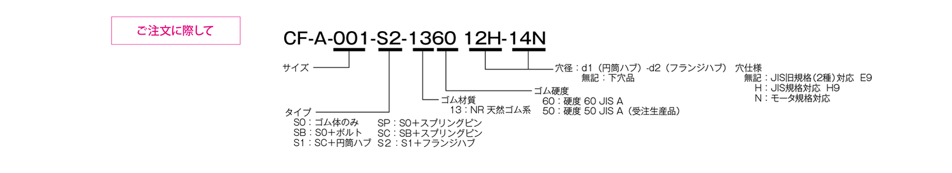
CF-A [S0] Plug-in Mounting Type
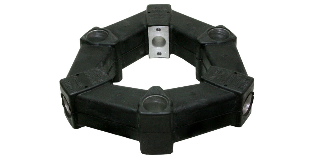
Power is transmitted via pre-compressed rubber. It excels at absorbing vibrations and shocks, and also reduces noise from machinery. The elastic rubber component consists of a polygonal rubber body with aluminum inserts at its vertices. Installation is simply a matter of sliding it onto the shaft; the S0 type is supplied with the rubber body only.
[Specifications]
| Model | Torque | Tolerance | Maximum Rotational Speed | Dynamic torsional spring constant | Moment of inertia | Mass | Price | ||||
|---|---|---|---|---|---|---|---|---|---|---|---|
| Standard | Maximum | Permissible variation | Eccentricity | Angular Deviation | Axial | ||||||
| [N·m] | [N·m] | [N·m/10 Hz] | [mm] | [°] | [mm] | [min⁻¹] | [N·m/rad] | [kg·m²] | [kg] | [JPY] | |
| CF-A-001-S0-1360 | 10 | 25 | ±4 | 0.5 | 3 | ±2 | 10,000 | 1.47×10² | 1.9×10⁻⁵ | 0.1 | |
| CF-A-002-S0-1360 | 20 | 50 | ±8 | 1 | 3 | ±3 | 8,000 | 2.92×10² | 1.2×10⁻⁴ | 0.1 | |
| CF-A-004-S0-1360 | 40 | 100 | ±16 | 1 | 3 | ±3 | 7,000 | 7.59×10² | 2.6×10⁻⁴ | 0.2 | |
| CF-A-008-S0-1360 | 80 | 200 | ±32 | 1 | 3 | ±4 | 6500 | 1.44×10³ | 7.2×10⁻⁴ | 0.3 | |
| CF-A-012-S0-1360 | 120 | 300 | ±48 | 1 | 2 | ±4 | 6,500 | 4.38×10³ | 7.6×10⁻⁴ | 0.3 | |
| CF-A-016-S0-1360 | 160 | 400 | ±64 | 1.5 | 3 | ±5 | 6000 | 3.28×10³ | 2.4×10⁻³ | 0.6 | |
| CF-A-022-S0-1360 | 220 | 550 | ±88 | 1.5 | 2 | ±5 | 6000 | 8.26×10³ | 2.6×10⁻³ | 0.7 | |
| CF-A-025-S0-1360 | 250 | 630 | ±100 | 1.5 | 3 | ±5 | 5000 | 4.12×10³ | 4.0×10⁻³ | 0.8 | |
| CF-A-028-S0-1360 | 350 | 880 | ±140 | 1.5 | 2 | ±5 | 5000 | 1.05×10⁴ | 4.3×10⁻³ | 0.9 | |
| CF-A-030-S0-1360 | 400 | 1000 | ±160 | 1.5 | 3 | ±5 | 4000 | 6.40×10³ | 1.0×10⁻² | 1.4 | |
| CF-A-050-S0-1360 | 600 | 1500 | ±240 | 1.5 | 2 | ±5 | 4000 | 1.48×10⁴ | 1.1×10⁻² | 1.7 | |
| CF-A-080-S0-1360 | 800 | 2000 | ±320 | 1.5 | 2 | ±4 | 4000 | 2.17×10⁴ | 1.5×10⁻² | 2.3 | |
| CF-A-090-S0-1360 | 900 | 2250 | ±360 | 1.5 | 3 | ±5 | 3600 | 1.37×10⁴ | 3.6×10⁻² | 3.1 | |
| CF-A-140-S0-1360 | 1400 | 3500 | ±560 | 1.5 | 2 | ±5 | 3600 | 2.90×10⁴ | 3.8×10⁻² | 3.4 | |
| CF-A-200-S0-1360 | 2000 | 5000 | ±800 | 1.5 | 2 | ±5 | 3200 | 6.08×10⁴ | 7.5×10⁻² | 5.3 | |
| CF-A-250-S0-1360 | 3000 | 8750 | ±1250 | 1.5 | 2 | ±5 | 3000 | 8.28×10⁴ | 0.14 | 7.0 | |
| CF-A-400-S0-1360 | 5000 | 12,500 | ±2000 | 1.5 | 2 | ±5 | 2800 | 1.25×10⁵ | 0.22 | 10.7 | |
- The maximum rotational speed does not take dynamic balance into account.
- As a general rule, the dynamic torsional spring constant is approximately 1.3 times the static torsional spring constant.
[Dimensions]
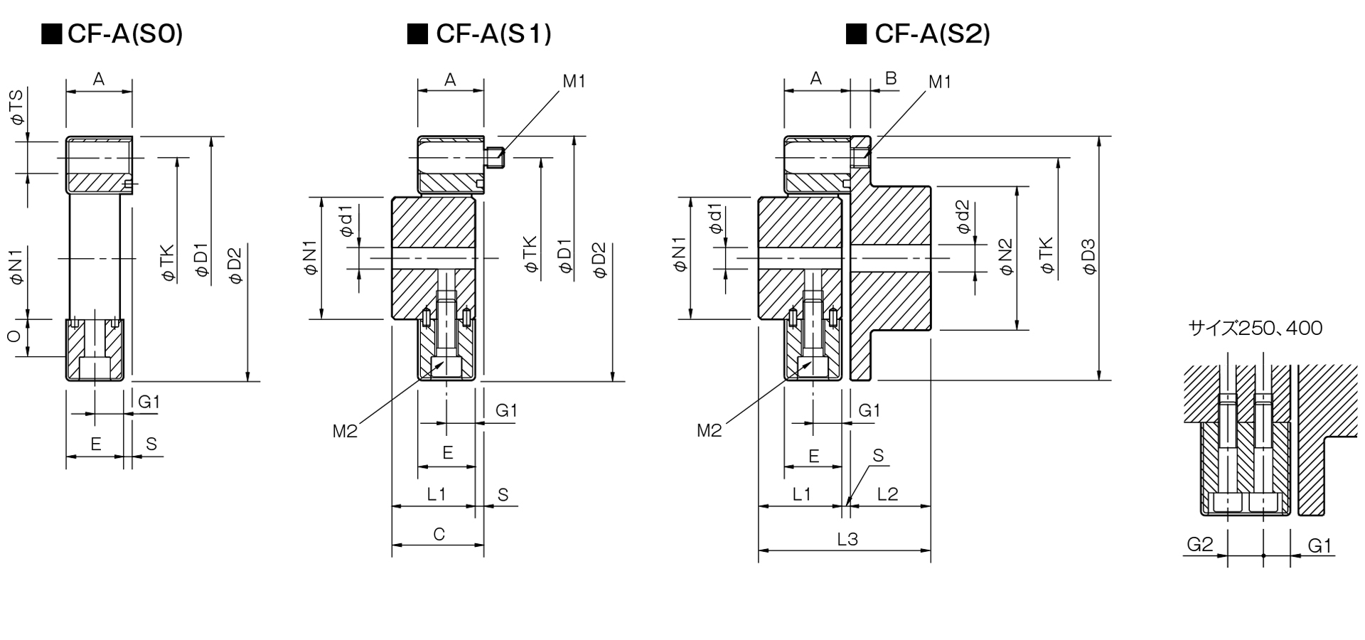
Unit [mm]
| Model | d1 | d2 | D1 | D2 | D3 | N1 | N2 | L1 | L2 | L3 | A | B | C | E | G1 | G2 | O | S | TS | TK | M1 | M2 | ||||
|---|---|---|---|---|---|---|---|---|---|---|---|---|---|---|---|---|---|---|---|---|---|---|---|---|---|---|
| Pilot hole | Minimum | Max | Pilot hole | Minimum | Max | |||||||||||||||||||||
| CF-A-001 | 8 | 9 | 19 | 8 | 9 | 22 | 57 | 56 | 56 | 30 | 36 | 32 | 24 | 58 | 24 | 7 | 34 | 22 | 11 | - | 5 | 2 | 10 | 44 | 2-M6 | 2-M6 |
| CF-A-002 | 10 | 11 | 28 | 9 | 10 | 30 | 86 | 85 | 85 | 40 | 45 | 30 | 28 | 62 | 24 | 8 | 34 | 20 | 10 | - | 14 | 4 | 14 | 68 | 2-M8 | 2-M8 |
| CF-A-004 | 12 | 14 | 30 | 11 | 12 | 36 | 100 | 97 | 100 | 45 | 55 | 34 | 30 | 68 | 28 | 8 | 38 | 24 | 12 | - | 18.3 | 4 | 14 | 80 | 3-M8 | 3-M8 |
| CF-A-008 | 12 | 14 | 38 | 15 | 16 | 46 | 122 | 120 | 120 | 60 | 70 | 40 | 42 | 86 | 32 | 10 | 44 | 28 | 14 | - | 20.5 | 4 | 17 | 100 | 3-M10 | 3-M10 |
| CF-A-012 | 12 | 14 | 38 | 15 | 16 | 46 | 122 | 120 | 120 | 60 | 70 | 40 | 42 | 86 | 32 | 10 | 44 | 28 | 14 | - | 20.5 | 4 | 17 | 100 | 4-M10 | 4-M10 |
| CF-A-016 | 15 | 16 | 48 | 19 | 20 | 56 | 150 | 150 | 150 | 70 | 85 | 52 | 50 | 108 | 42 | 12 | 58 | 36 | 18 | - | 25 | 6 | 19 | 125 | 3-M12 | 3-M12 |
| CF-A-022 | 15 | 16 | 48 | 19 | 20 | 56 | 150 | 150 | 150 | 70 | 85 | 52 | 50 | 108 | 42 | 12 | 58 | 36 | 18 | - | 25 | 6 | 19 | 125 | 4-M12 | 4-M12 |
| CF-A-025 | 15 | 16 | 55 | 19 | 20 | 65 | 170 | 170 | 170 | 85 | 100 | 58 | 56 | 120 | 46 | 14 | 64 | 40 | 20 | - | 26 | 6 | 22 | 140 | 3-M14 | 3-M14 |
| CF-A-028 | 15 | 16 | 55 | 19 | 20 | 65 | 170 | 170 | 170 | 85 | 100 | 58 | 56 | 120 | 46 | 14 | 64 | 40 | 20 | - | 26 | 6 | 22 | 140 | 4-M14 | 4-M14 |
| CF-A-030 | 20 | 22 | 65 | 28 | 30 | 80 | 200 | 200 | 200 | 100 | 120 | 68 | 66 | 142 | 58 | 16 | 76 | 50 | 25 | - | 33 | 8 | 25 | 165 | 3-M16 | 3-M16 |
| CF-A-050 | 20 | 22 | 65 | 28 | 30 | 80 | 200 | 200 | 200 | 100 | 120 | 68 | 66 | 142 | 58 | 16 | 76 | 50 | 25 | - | 33 | 8 | 25 | 165 | 4-M16 | 4-M16 |
| CF-A-080 | 20 | 22 | 65 | 28 | 30 | 80 | 205 | 205 | 200 | 100 | 120 | 80 | 66 | 150 | 65 | 16 | 84 | 61 | 30.5 | - | 33 | 4 | 25 | 165 | 4-M16 | 4-M16 |
| CF-A-090 | 30 | 32 | 85 | 30 | 32 | 95 | 260 | 260 | 260 | 125 | 140 | 84 | 80 | 172 | 70 | 19 | 92 | 62 | 31 | - | 46 | 8 | 32 | 215 | 3-M20 | 3-M20 |
| CF-A-140 | 30 | 32 | 85 | 30 | 32 | 95 | 260 | 260 | 260 | 125 | 140 | 84 | 80 | 172 | 70 | 19 | 92 | 62 | 31 | - | 46 | 8 | 32 | 215 | 4-M20 | 4-M20 |
| CF-A-200 | 35 | 38 | 105 | 35 | 38 | 110 | 300 | 300 | 300 | 145 | 160 | 94 | 90 | 192 | 80 | 19 | 102 | 72 | 36 | - | 46 | 8 | 32 | 250 | 4-M20 | 4-M20 |
| CF-A-250 | 40 | 42 | 115 | 40 | 42 | 120 | 340 | 340 | 340 | 160 | 180 | 100 | 100 | 208 | 85 | 19 | 108 | 77 | 22.5 | 32 | 60 | 8 | 32 | 280 | 4-M20 | 8-M20 |
| CF-A-400 | 40 | 42 | 115 | 40 | 42 | 130 | 370 | 370 | 370 | 170 | 200 | 125 | 125 | 260 | 105 | 29 | 135 | 95 | 28.5 | 38 | 70.5 | 10 | 45 | 300 | 4-M24 | 8-M20 |
- The pilot hole is a drill hole. The minimum values for d1 and d2 indicate the minimum hole diameters specified in our standard hole machining specifications, while the maximum values indicate the largest hole diameters that can be machined.
- The TK dimension corresponds to the bolt mounting pitch diameter of the flange hub or mating mounting surface; however, it can be modified to facilitate installation, so please contact us for details.
- The TS dimensions are based on the H8 plug gauge standard. However, the tolerance for size 001 is +0.10, and for sizes 002 and 004, it is +0.150.
- The designation for M1 and M2 bolts consists of the quantity followed by the thread size.
- When using hex socket head cap screws with the CF-A-400, you must use the special flat washers included with the rubber body.