MF Model

This metal coupling utilizes the elasticity of a spring structure and incorporates a metal coil spring. This model offers high flexibility and is capable of accommodating significant misalignments, such as eccentricity and angular misalignment.While retaining the three-layer structure of the coil spring section, this model has been designed for versatility by shaping one side of the hub into a flange.
[Specifications]
| Model | Rated Torque [N·m] | Tolerance | Maximum rotational speed [min⁻¹] | Torsional spring constant [N·m/rad] | Moment of Inertia [kg·m²] | Mass [kg] | Price of pre-drilled product [JPY] | ||
|---|---|---|---|---|---|---|---|---|---|
| Eccentricity [mm] | Angular offset [°] | Axial length [mm] | |||||||
| MF-8K | 5 | 0.3 | 3 | 0.8 | 15,000 | 286.5 | 1.66×10⁻⁵ | 0.1 | |
| MF-12K | 10 | 0.4 | 1 | 12,000 | 573 | 3.32×10⁻⁵ | 0.16 | ||
| MF-16K | 20 | 0.6 | 1.2 | 9000 | 1146 | 9.18×10⁻⁵ | 0.31 | ||
| MF-20K | 40 | 0.7 | 1.6 | 7000 | 2292 | 2.12×10⁻⁴ | 0.5 | ||
| MF-25K | 90 | 0.9 | 2 | 6000 | 3438 | 5.33×10⁻⁴ | 0.9 | ||
| MF-30K | 150 | 1.1 | 2.5 | 5000 | 4297.5 | 1.35×10⁻³ | 1.7 | ||
| MF-35K | 220 | 1.2 | 3.2 | 4500 | 6303 | 2.86×10⁻³ | 2.8 | ||
- The maximum rotational speed does not take dynamic balance into account.
- The moment of inertia and mass are based on the maximum bore diameter.
[Dimensions]
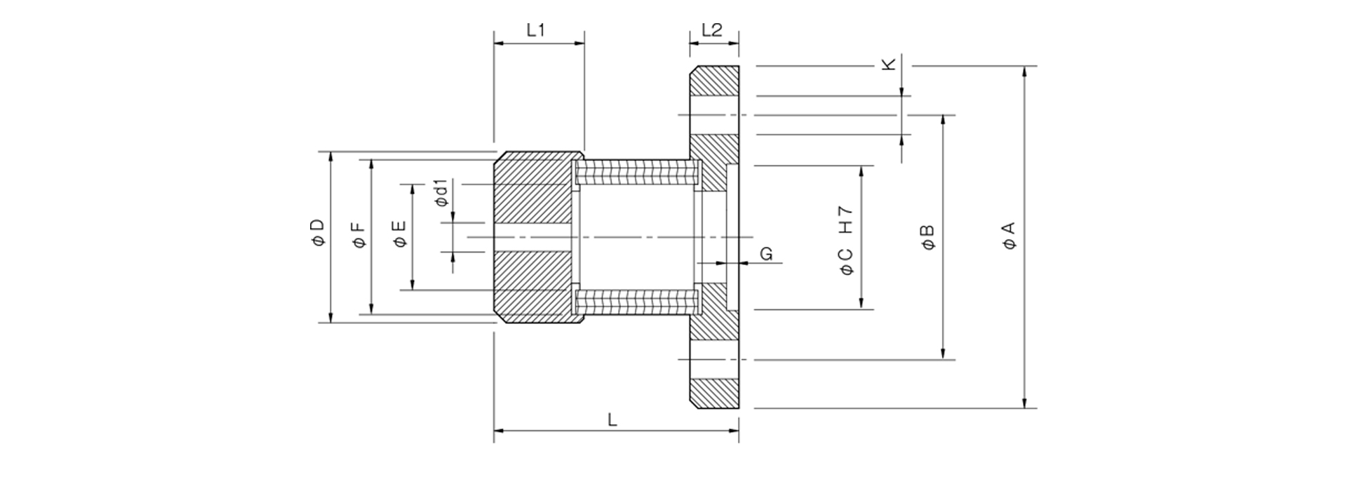
Unit [mm]
| Model | d1 | D | L | L1 | L2 | A | B | C | E | F | G | K | CAD File No. | ||
|---|---|---|---|---|---|---|---|---|---|---|---|---|---|---|---|
| Pilot hole | Minimum | Max | |||||||||||||
| MF-8K | 3.5 | 4 | 8 | 21 | 30 | 11 | 6 | 42 | 30 | 18 | 13 | 19 | 1.5 | 3–φ4.8 | MF-K1 |
| MF-12K | 5.5 | 6 | 12 | 26 | 40 | 16.5 | 48 | 37 | 22 | 16.5 | 24 | MF-K2 | |||
| MF-16K | 10 | 16 | 35 | 50 | 22 | 6.5 | 58 | 47 | 30 | 22.4 | 32 | 4–φ4.8 | MF-K3 | ||
| MF-20K | 12 | 20 | 45 | 60 | 27 | 7 | 65 | 52 | 35 | 28 | 40 | MF-K4 | |||
| MF-25K | 14 | 25 | 55 | 75 | 33.5 | 8.5 | 75 | 62 | 42 | 35 | 50 | 6– φ 5.8 | MF-K5 | ||
| MF-30K | 16 | 30 | 65 | 95 | 40 | 10 | 90 | 74.5 | 47 | 40.8 | 60 | 2.5 | 4–φ7.0 | MF-K6 | |
| MF-35K | 20 | 35 | 75 | 115 | 48 | 13 | 100 | 84 | 57 | 46 | 70 | 6– φ 7.0 | MF-K7 | ||
- The pilot hole will be a drill hole.

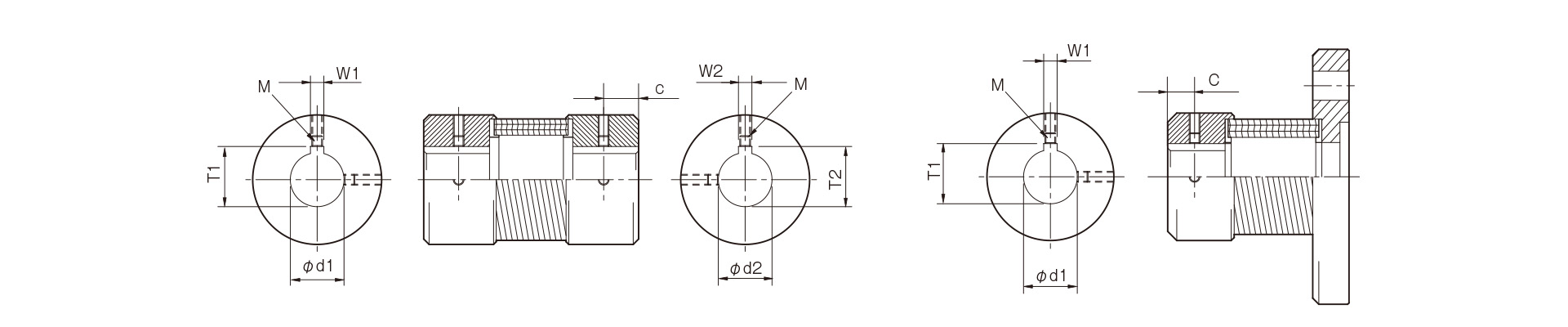
[Standard Hole Drilling Specifications]
Unit [mm]
| Compliant with JIS B 1301 1959 (Type 2) | Compliant with JIS New Standard H9 JIS B 1301 1996 | Compliant with JIS New Standard JS9 JIS B 1301 1996 | Motor Standard: Compliant with JIS C 4210 2001 | ||||||||||||||||
|---|---|---|---|---|---|---|---|---|---|---|---|---|---|---|---|---|---|---|---|
| Nominal hole diameter | Bore Diameter (d1, d2) | Keyway width (W1, W2) | Keyway depth (T1, T2) | Set screw hole (M) | Nominal hole diameter | Hole diameter (d1, d2) | Keyway width (W1, W2) | Keyway depth (T1, T2) | Set screw hole (M) | Nominal hole diameter | Hole diameter (d1, d2) | Keyway width (W1, W2) | Keyway depth (T1, T2) | Set screw hole (M) | Nominal hole diameter | Hole diameter (d1, d2) | Keyway width (W1, W2) | Keyway depth (T1, T2) | Set screw hole (M) |
| Nominal hole diameter | Tolerance H7, H8 | Tolerance E9 | - | - | Nominal hole diameter | Tolerance H7 | Tolerance H9 | - | - | Nominal hole diameter | Tolerance H7 | Tolerance JS9 | - | - | Nominal hole diameter | Tolerance G7, F7 | Tolerance H9 | - | - |
| 4 | 4+0.0180 | - | - | 2-M3 | - | - | - | - | - | - | - | - | - | - | - | - | - | - | - |
| 5 | 5+0.0180 | ||||||||||||||||||
| 6 | 6 + 0.0180 | 2-M4 | |||||||||||||||||
| 7 | 7 + 0.0220 | ||||||||||||||||||
| 8 | 8 + 0.0220 | ||||||||||||||||||
| 9 | 9 + 0.0220 | ||||||||||||||||||
| 10 | 10 + 0.0220 | ||||||||||||||||||
| 11 | 11 + 0.0180 | ||||||||||||||||||
| 12 | 12 + 0.0180 | 4 + 0.050 + 0.020 | 13.5 + 0.30 | 12H | 12 + 0.0180 | 4 + 0.0300 | 13.8 + 0.30 | 2-M4 | 12J | 12 + 0.0180 | 4±0.0150 | 13.8 + 0.30 | 2-M4 | ||||||
| 14 | 14 + 0.0180 | 5 + 0.050 + 0.020 | 16.0 + 0.30 | 14H | 14 + 0.0180 | 5 + 0.0300 | 16.3 + 0.30 | 14J | 14 + 0.0180 | 5 ± 0.0150 | 16.3 + 0.30 | 14N | 14 + 0.024 + 0.006 | 5 + 0.0300 | 16.3 + 0.30 | 2-M4 | |||
| 15 | 15 + 0.0180 | 17.0 + 0.30 | 15H | 15 + 0.0180 | 17.3 + 0.30 | 15J | 15 + 0.0180 | 17.3 + 0.30 | - | - | - | - | - | ||||||
| 16 | 16 + 0.0180 | 18.0 + 0.30 | 16H | 16 + 0.0180 | 18.3 + 0.30 | 16J | 16 + 0.0180 | 18.3 + 0.30 | |||||||||||
| 17 | 17 + 0.0180 | 19.0 + 0.30 | 17H | 17 + 0.0180 | 19.3 + 0.30 | 17J | 17 + 0.0180 | 19.3 + 0.30 | |||||||||||
| 18 | 18 + 0.0180 | 20.0 + 0.30 | 18H | 18 + 0.0180 | 6 + 0.0300 | 20.8 + 0.30 | 2-M5 | 18J | 18 + 0.0180 | 6±0.0150 | 20.8 + 0.30 | 2-M5 | |||||||
| 19 | 19 + 0.0210 | 21.0 + 0.30 | 19H | 19 + 0.0210 | 21.8 + 0.30 | 19J | 19 + 0.0210 | 21.8 + 0.30 | 19N | 19 + 0.028 + 0.007 | 6 + 0.0300 | 21.8 + 0.30 | 2-M5 | ||||||
| 20 | 20 + 0.0210 | 22.0 + 0.30 | 20H | 20 + 0.0210 | 22.8 + 0.30 | 20J | 20 + 0.0210 | 22.8 + 0.30 | - | - | - | - | - | ||||||
| 22 | 22 + 0.0210 | 7 + 0.06 1 + 0.025 | 25.0 + 0.30 | 2-M6 | 22H | 22 + 0.0210 | 24.8 + 0.30 | 22J | 22 + 0.0210 | 24.8 + 0.30 | |||||||||
| 24 | 24 + 0.0210 | 27.0 + 0.30 | 24H | 24 + 0.0210 | 8 + 0.0360 | 27.3 + 0.30 | 2-M6 | 24J | 24 + 0.0210 | 8±0.0180 | 27.3 + 0.30 | 2-M6 | 24N | 24 + 0.028 + 0.007 | 8 + 0.0360 | 27.3 + 0.30 | 2-M6 | ||
| 25 | 25 + 0.0210 | 28.0 + 0.30 | 25H | 25 + 0.0210 | 28.3 + 0.30 | 25J | 25 + 0.0210 | 28.3 + 0.30 | - | - | - | - | - | ||||||
| 28 | 28 + 0.0210 | 31.0 + 0.30 | 28H | 28 + 0.0210 | 31.3 + 0.30 | 28J | 28 + 0.0210 | 31.3 + 0.30 | 28N | 28 + 0.028 + 0.007 | 8 + 0.0360 | 31.3 + 0.30 | 2-M6 | ||||||
| 30 | 30 + 0.0210 | 33.0 + 0.30 | 30H | 30 + 0.0210 | 33.3 + 0.30 | 30J | 30 + 0.0210 | 33.3 + 0.30 | - | - | - | - | - | ||||||
| 32 | 32 + 0.0250 | 10 + 0.06 1 + 0.025 | 35.5 + 0.30 | 2-M8 | 32H | 32 + 0.0250 | 10 + 0.0360 | 35.3 + 0.30 | 2-M8 | 32J | 32 + 0.0250 | 10±0.0180 | 35.3 + 0.30 | 2-M8 | |||||
| 35 | 35 + 0.0250 | 38.5 + 0.30 | 35H | 35 + 0.0250 | 38.3 + 0.30 | 35J | 35 + 0.0250 | 38.3 + 0.30 | |||||||||||
- This standard hole drilling specification applies to Baumannflex MM and MF models.
- All specifications for diameters of 11 mm or less are identical to those listed in the "Old JIS Standards" column.
- The set screws are not located on the same plane.
- The set screw is included with the product.
- The positional accuracy of keyway machining is checked visually.
- Please contact us if you require positional accuracy for the keyways relative to each hub.
- For standard dimensions of hole patterns other than those listed here, please refer to the technical data at the end of this document.
[Location of the set screw]
| Coupling Size | Distance C from end face [mm] |
|---|---|
| 6 | 3 |
| 8 | 5 |
| 12・14 | 7 |
| 16, 19, 20, 24 | 10 |
| 25, 28, 30, 35 | 15 |