Type 102 (33, 35, 31)

This is a micro-sized lineup of electromagnetically operated clutches that activate when an electric current is applied to the coil. Featuring a bearing-mounted design that allows for installation without worrying about alignment or centering, the series offers three types of armature assemblies with different mounting configurations, enabling selection based on specific installation requirements.
[Specifications] For direct installation
| Model | Size | Static Friction Torque Td [N·m] | Coil (at 20°C) | Lead wire | Temperature Class | Maximum rotational speed [min⁻¹] | Rotating mass moment of inertia J | Allowable coupling work Eeaℓ [J] | Total work until air gap readjustment ET [J] | Armature attraction time ta [s] | Torque rise time tp [s] | Torque decay time td [s] | Mass [kg] | |||||
|---|---|---|---|---|---|---|---|---|---|---|---|---|---|---|---|---|---|---|
| Voltage [V] | Power [W] | Current [A] | Resistance [Ω] | UL Style | Size | Armature [kg·m²] | Rotor [kg·m²] | |||||||||||
| 102-02-33 | 2 | 0.4 | DC24 | 6 | 0.25 | 96 | UL3398 | AWG 26 | B | 500 | 6.75×10⁻⁷ | 2.75×10⁻⁶ | 1500 | 2×10⁶ | 0.009 | 0.019 | 0.017 | 0.076 |
| 102-02-35 | 2 | 0.4 | DC24 | 6 | 0.25 | 96 | UL3398 | AWG 26 | B | 500 | 1.00×10⁻⁶ | 2.75×10⁻⁶ | 1500 | 2×10⁶ | 0.009 | 0.019 | 0.017 | 0.082 |
| 02/31/102 | 2 | 0.4 | DC24 | 6 | 0.25 | 96 | UL3398 | AWG 26 | B | 500 | 1.00×10⁻⁶ | 2.75×10⁻⁶ | 1500 | 2×10⁶ | 0.009 | 0.019 | 0.017 | 0.08 |
| March 33, 2010 | 3 | 0.6 | DC24 | 6 | 0.25 | 96 | UL3398 | AWG 26 | B | 500 | 1.30×10⁻⁶ | 4.08×10⁻⁶ | 2300 | 3×10⁶ | 0.009 | 0.022 | 0.02 | 0.101 |
| March 35, 2010 | 3 | 0.6 | DC24 | 6 | 0.25 | 96 | UL3398 | AWG 26 | B | 500 | 1.95×10⁻⁶ | 4.08×10⁻⁶ | 2300 | 3×10⁶ | 0.009 | 0.022 | 0.02 | 0.11 |
| March 31, 2010 | 3 | 0.6 | DC24 | 6 | 0.25 | 96 | UL3398 | AWG 26 | B | 500 | 1.95×10⁻⁶ | 4.08×10⁻⁶ | 2300 | 3×10⁶ | 0.009 | 0.022 | 0.02 | 0.108 |
| April 33, 2010 | 4 | 1.2 | DC24 | 8 | 0.33 | 72 | UL3398 | AWG 26 | B | 500 | 4.38×10⁻⁶ | 1.44×10⁻⁵ | 4500 | 6×10⁶ | 0.011 | 0.028 | 0.03 | 0.183 |
| 102-04-35 | 4 | 1.2 | DC24 | 8 | 0.33 | 72 | UL3398 | AWG 26 | B | 500 | 6.15×10⁻⁶ | 1.44×10⁻⁵ | 4500 | 6×10⁶ | 0.011 | 0.028 | 0.03 | 0.2 |
| April 31, 2010 | 4 | 1.2 | DC24 | 8 | 0.33 | 72 | UL3398 | AWG 26 | B | 500 | 6.15×10⁻⁶ | 1.44×10⁻⁵ | 4500 | 6×10⁶ | 0.011 | 0.028 | 0.03 | 0.196 |
| May 33, 2010 | 5 | 2.4 | DC24 | 10 | 0.42 | 58 | UL3398 | AWG 22 | B | 500 | 9.08×10⁻⁶ | 2.90×10⁻⁵ | 9000 | 9×10⁶ | 0.012 | 0.031 | 0.04 | 0.321 |
| May 35, 2010 | 5 | 2.4 | DC24 | 10 | 0.42 | 58 | UL3398 | AWG 22 | B | 500 | 1.38×10⁻⁵ | 2.90×10⁻⁵ | 9000 | 9×10⁶ | 0.012 | 0.031 | 0.04 | 0.346 |
| May 31, 2010 | 5 | 2.4 | DC24 | 10 | 0.42 | 58 | UL3398 | AWG 22 | B | 500 | 1.38×10⁻⁵ | 2.90×10⁻⁵ | 9000 | 9×10⁶ | 0.012 | 0.031 | 0.04 | 0.336 |
- The dynamic friction torque Td is the value at a relative speed of 100 min⁻¹. Additionally, depending on the initial torque characteristics, a break-in period may be required.
- Keep fluctuations in the supply voltage within ±10% of the coil voltage. Also, ensure that the duty cycle does not exceed 80%.
- The moment of inertia and mass of the rotating section are based on the values at the maximum bore diameter.
[Dimensions] For direct installation
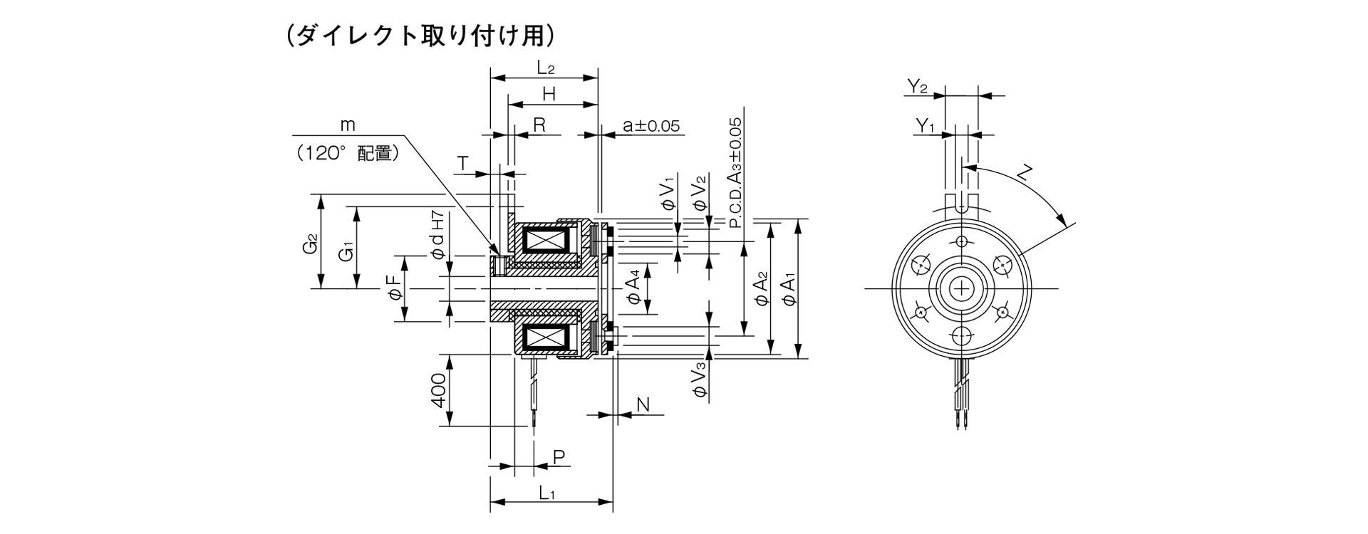
Unit [mm]
| Size | Radial dimensions | Axial dimensions | CAD File No. | ||||||||||||||||||||
|---|---|---|---|---|---|---|---|---|---|---|---|---|---|---|---|---|---|---|---|---|---|---|---|
| A1 | A2 | A3 | A4 | F | V1 | V2 | V3 | G1 | G2 | Y1 | Y2 | Z | m | H | R | L1 | L2 | P | N | T | a | ||
| 02 | 31 | 28 | 19.5 | 10.7 | 14 | 2–2.1 | 2-5.3 | 2-3.7 | 15.8 | 19.8 | 3.1 | 8 | 4–90° | 2-M3 | 19.1 | 1.2 | 25.9 | 23.5 | 4.9 | 0.8 | 2.5 | 0.1 | 102-331 |
| 03 | 34 | 32 | 23 | 12.5 | 16 | 3–2.6 | 3-6 | 3-4.5 | 20 | 23 | 3.1 | 8 | 6–60° | 2-M3 | 22 | 1.6 | 28.5 | 26.2 | 4.7 | 1.2 | 2.3 | 0.15 | 102–332 |
| 04 | 43 | 40 | 30 | 18.5 | 22 | 3-3.1 | 3-6 | 3-5 | 23 | 26 | 3.1 | 8 | 6–60° | 2-M4 | 25.2 | 1.6 | 33.1 | 30.4 | 5.2 | 1.5 | 2.8 | 0.15 | 102–333 |
| 05 | 54 | 50 | 38 | 25.5 | 30 | 3–3.1 | 3–6.5 | 3-6 | 28 | 31 | 3.1 | 8 | 6–60° | 2-M5 | 27.9 | 1.6 | 37.3 | 34.1 | 6.2 | 1.5 | 3.3 | 0.2 | 102–334 |
Unit [mm]
| Size | Shaft bore dimensions |
|---|---|
| d1 H7 | |
| 02 | 5 |
| 03 | 6 |
| 04 | 8 |
| 10 | |
| 05 | 10 |
| 15 |
- For information regarding installation methods, please refer to the design specifications.

[Dimensions] For through-shafts
4. Heading (H4)-1
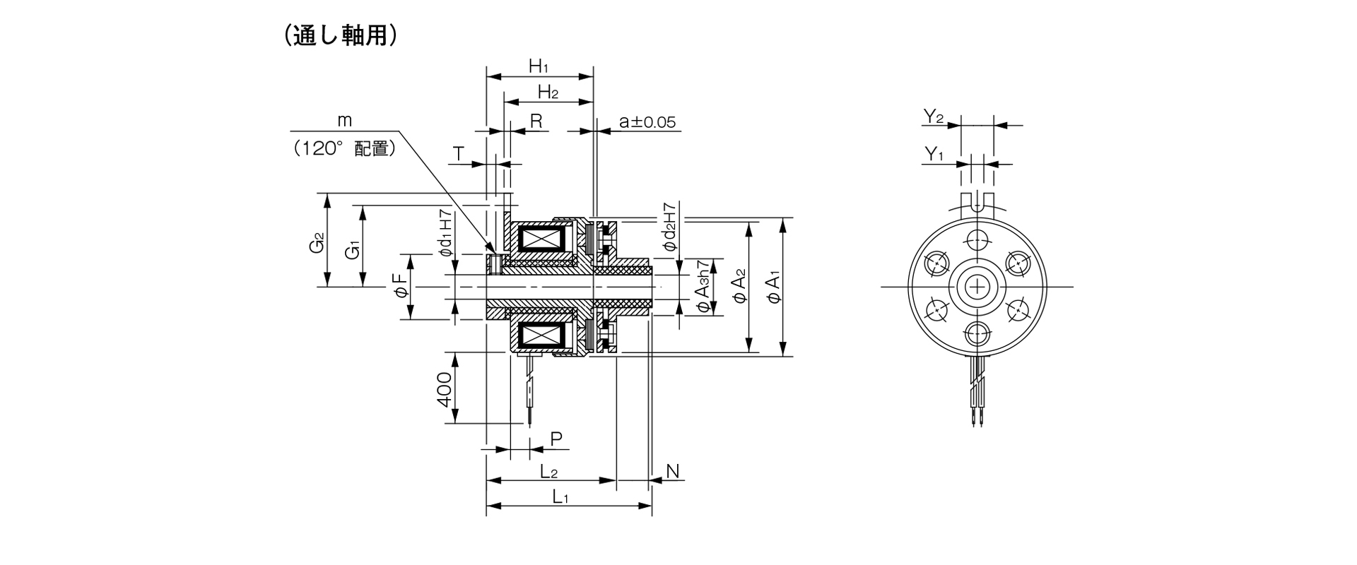
Unit [mm]
| Size | Radial dimensions | Axial dimensions | CAD File No. | ||||||||||||||||
|---|---|---|---|---|---|---|---|---|---|---|---|---|---|---|---|---|---|---|---|
| A1 | A2 | A3 | F | G1 | G2 | Y1 | Y2 | m | H1 | H2 | R | L1 | L2 | P | N | T | a | ||
| 02 | 31 | 28 | 13 | 14 | 15.8 | 20 | 3.1 | 8 | 2-M3 | 23.5 | 19.1 | 1.2 | 33 | 27.9 | 4.9 | 4.8 | 2.5 | 0.1 | 102-351 |
| 03 | 34 | 32 | 14 | 16 | 20 | 23 | 3.1 | 8 | 2-M3 | 26.2 | 22 | 1.6 | 38.5 | 30.5 | 4.7 | 7.8 | 2.3 | 0.15 | 102–352 |
| 04 | 43 | 40 | 18 | 22 | 23 | 26 | 3.1 | 8 | 2-M4 | 30.4 | 25.2 | 1.6 | 45.2 | 35.8 | 5.2 | 9.1 | 2.8 | 0.15 | 102–353 |
| 05 | 54 | 50 | 28 | 30 | 28 | 31 | 3.1 | 8 | 2-M5 | 34.1 | 27.9 | 1.6 | 49.3 | 0.3 | 6.2 | 8.8 | 3.3 | 0.2 | 102–354 |
Unit [mm]
| Size | Shaft bore dimensions | |
|---|---|---|
| d1 H7 | d2 H7 | |
| 02 | 5 | 5 |
| 03 | 6 | 6 |
| 04 | 8 | 8 |
| 10 | 10 | |
| 05 | 10 | 10 |
| 15 | 15 | |
- For information regarding installation methods, please refer to the design specifications.

[Dimensions] For butt-joint shafts
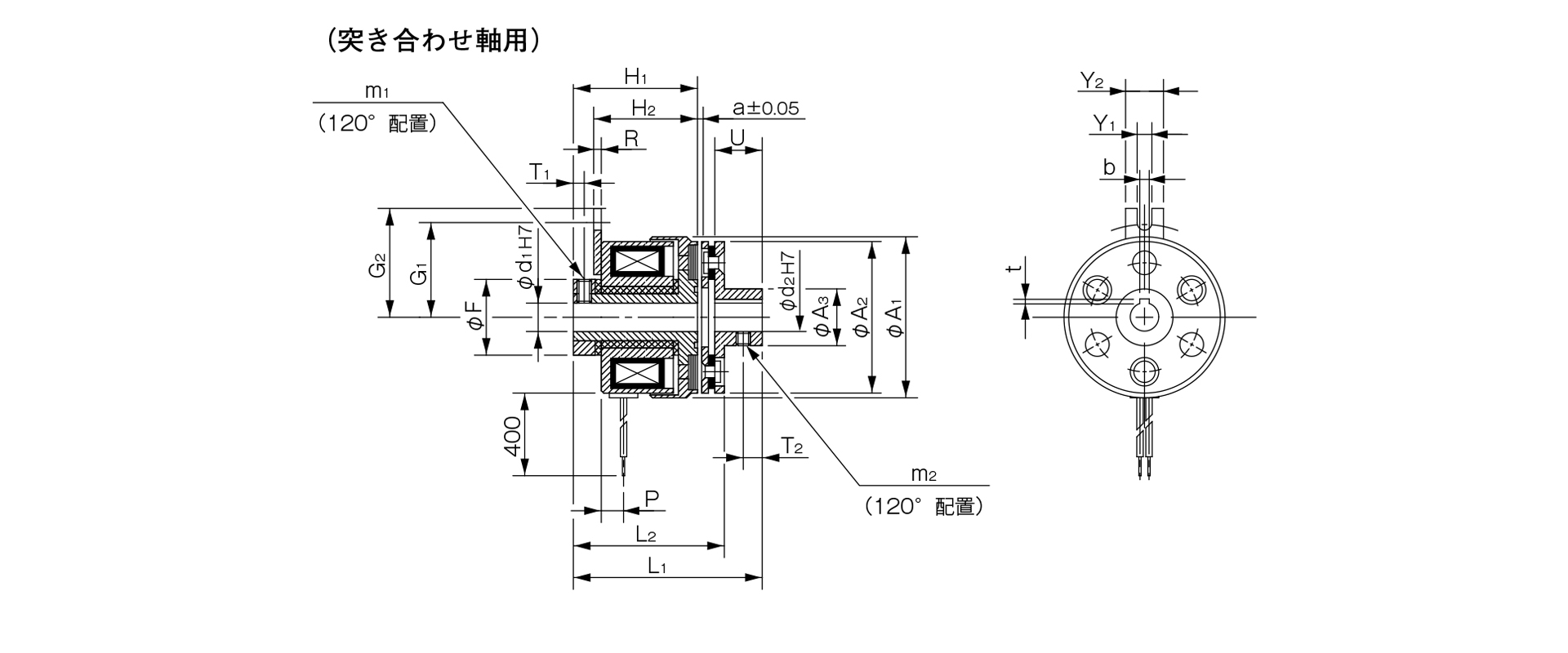
Unit [mm]
| Size | Radial dimensions | Axial dimensions | CAD File No. | ||||||||||||||||||
|---|---|---|---|---|---|---|---|---|---|---|---|---|---|---|---|---|---|---|---|---|---|
| A1 | A2 | A3 | F | G1 | G2 | Y1 | Y2 | m1 | m2 | H1 | H2 | R | L1 | L2 | P | U | T1 | T2 | a | ||
| 02 | 31 | 28 | 9.5 | 14 | 15.8 | 20 | 3.1 | 8 | 2-M3 | M3 | 23.5 | 19.1 | 1.2 | 32.9 | 27.9 | 4.9 | 7 | 2.5 | 2.5 | 0.1 | 102-311 |
| 03 | 34 | 32 | 12 | 16 | 20 | 23 | 3.1 | 8 | 2-M3 | 2-M3 | 26.2 | 22 | 1.6 | 38.5 | 30.5 | 4.7 | 10 | 2.3 | 4 | 0.15 | 102–312 |
| 04 | 43 | 40 | 17 | 22 | 23 | 26 | 3.1 | 8 | 2-M4 | 2-M3 | 30.4 | 25.2 | 1.6 | 45.1 | 35.8 | 5.2 | 12 | 2.8 | 5 | 0.15 | 102–313 |
| 05 | 54 | 50 | 24 | 30 | 28 | 31 | 3.1 | 8 | 2-M5 | 2-M4 | 34.1 | 27.9 | 1.6 | 49.3 | 40.3 | 6.2 | 12 | 3.3 | 5 | 0.2 | 102–314 |
Unit [mm]
| Size | Shaft Bore Dimensions | |||||
|---|---|---|---|---|---|---|
| d1 H7 | d2 H7 | Compliant with JIS standards | Compliant with old JIS standards | |||
| d1 H7 | b P9 | t | b E9 | t | ||
| 02 | 5 | 5 | - | - | - | - |
| 03 | 6 | 6 | 2–0.006–0.031 | 0.8 + 0.30 | - | - |
| 04 | 8 | 8 | 2–0.006–0.031 | 0.8 + 0.30 | - | - |
| 10 | 10 | 3–0.006–0.031 | 1.2 + 0.30 | 4 + 0.050 + 0.020 | 1.5 + 0.50 | |
| 05 | 10 | 10 | 3–0.006–0.031 | 1.2 + 0.30 | 4 + 0.050 + 0.020 | 1.5 + 0.50 |
| 15 | 15 | 5–0.012–0.042 | 2 + 0.50 | 5 + 0.050 + 0.020 | 2 + 0.50 | |
- For information regarding installation methods, please refer to the design specifications.