
BEH Model (for ultra-high-speed control)
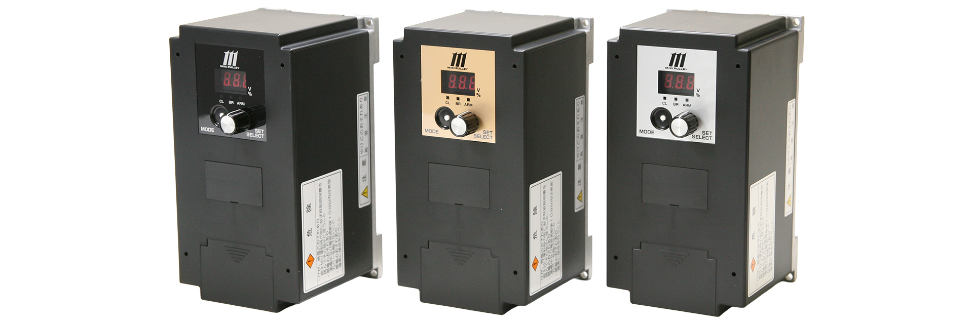
By incorporating a reverse excitation function in addition to over-excitation, we have dramatically improved the operating speed of electromagnetic clutches and brakes, enabling high-frequency and high-precision operation of various mechanical devices.Furthermore, optimal settings for operating our electromagnetically actuated clutches and brakes are pre-configured, eliminating the need for tedious adjustments.
[Specifications]
| Model | BEH-10G | BEH-20G | BEH-20G-1 | |
|---|---|---|---|---|
| Input Voltage | AC 200/220 V | AC 200/220 V | AC 100/115 V | |
| ±10% Single-phase 50/60 Hz | ||||
| Output Voltage | Over-excitation voltage | Initial value 100 V, adjustable from 0 to 250 V | ||
| Steady-state excitation voltage | Default: 24 V, adjustable from 0 to 250 V | |||
| Reverse excitation voltage | Default: 100 V, adjustable from 0 to 250 V | |||
| Voltage control method | PWM control | |||
| Output current | 2 A | 4 A | ||
| Applicable Clutch/Brake Sizes | 06–16 | 06–31 | ||
| Our Excitation Clutches and Brakes: Rated Voltage DC 24V | ||||
| Protection Functions | Undervoltage protection, overvoltage protection, overcurrent protection/detection, open-circuit detection, element overheat protection, input fuse (20A) | |||
| Operating Environment | –10 to +50°C / 10–90% RH | |||
| Weight | 0.85 kg | 0.9 kg | ||
[Pins and Functions]
| Terminal Symbols | Terminal Name | Function Description |
|---|---|---|
| R-S | Power Input Terminal | Connect to commercial power supply |
| CL-P | Clutch Output Terminal | Connect the clutch |
| BR-P | Brake output terminal | Connect the brake |
| 1 | Power terminal + | Positive terminal for control power supply (shared with internal +24V power supply) |
| 2 | Power Terminal - | Control power supply negative terminal (shared with internal 0V power supply) |
| 3 | Operation AUX | When Operation Setting Switch 5 (Operation AUX) is ON, the operation specified in the table settings is executed |
| 4 | Operation Clutch | Turns the output between P and CL ON/OFF |
| 5 | Operating Brake | Turns the output between P and BR ON/OFF |
| 6・7 | Alarm Output 1 | The relay operates when the alarm stops (relay output) |
| 8 | Alarm Output 2 | Outputs when the alarm is stopped (transistor output) |
[Characteristics]
Operational responsiveness
Fully solid-state, contactless circuitry gives BEH fast, stable input-to-output clutch/brake response. Overexcitation and reverse excitation maximize actuation speed, making it the flagship supply for ultra-high-speed, precision control.
Noise while driving
The BEH model is a quiet-running type. Normally, a humming sound is generated by the electromagnetic clutch and brake during operation, but thanks to its quiet design, the BEH model does not produce this sound.
Output Control Method
Selectable modes include Single Mode for independent clutch and brake control, and Interlock Mode for coordinated clutch/brake operation. Additional modes, including Current Control and JOG, support a wide range of applications.
Power Supply Voltage Fluctuations and Output Voltage
The BEH Model maintains constant output despite supply voltage fluctuations, ensuring stable output and consistent clutch/brake response. Excessive fluctuations trigger an alarm. For proper operation, keep supply voltage variations within ±10%
[Wiring Instructions and Timing Chart]
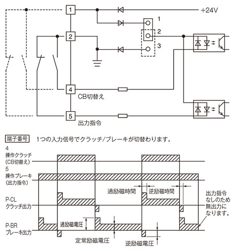
Linked Mode (Operation Setting SW-2 OFF)
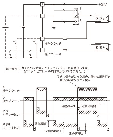
Single-action mode (Operation setting SW-2 ON)

[Dimensions]
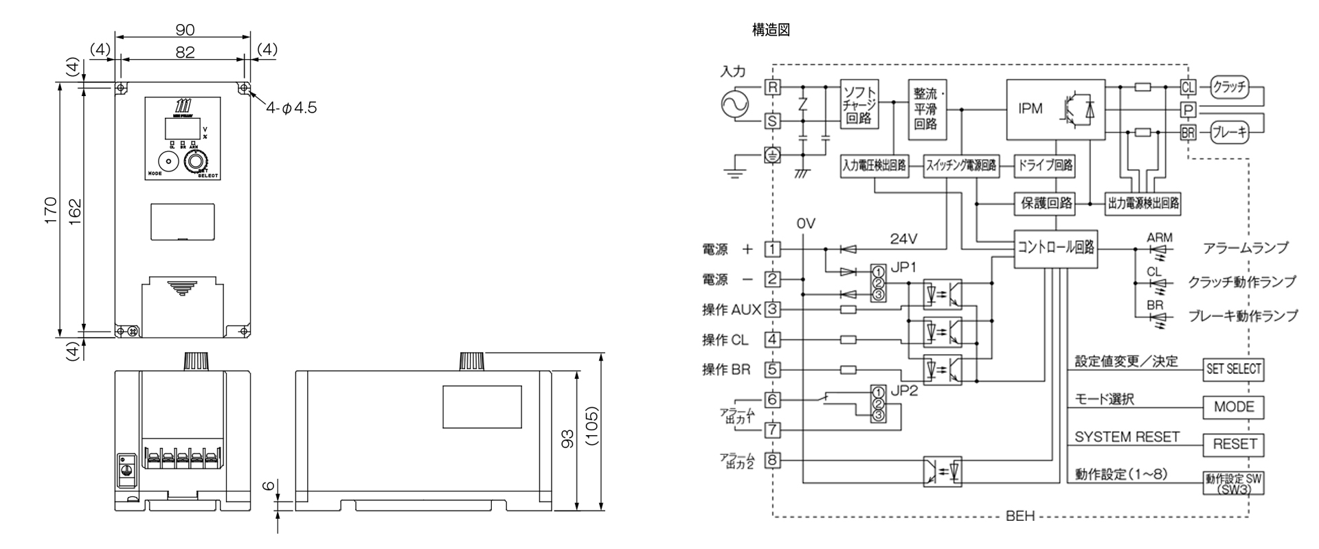
[Operation Settings]
| Operation Setting Switch (SW3) Switch No. | ON (up) | OFF (down) | Factory setting | |
|---|---|---|---|---|
| 1 | Setting/Operation Mode | Setup Mode | Operating Mode | OFF |
| 2 | Single/Interlock Mode | Single-action mode | Interlock Mode | OFF |
| 3 | Open Circuit/Overcurrent Detection | Enabled | Disabled | OFF |
| 4 | Current and Voltage Control | Current Control | Voltage Control | OFF |
| 5 | Operation AUX | Enabled | Disabled | OFF |
| 6 | JOG operation | Enabled | Disabled | OFF |
| 7 | Slope Operation | Enabled | Disabled | OFF |
| 8 | One-shot operation | Enabled | Disabled | OFF |
【端子と機能】
| 端子 記号 | 端子 名称 | 機能 説明 |
|---|---|---|
| R-S | 電源入力端子 | 商用電源を接続します |
| CL-P | クラッチ出力端子 | クラッチを接続します |
| BR-P | ブレーキ出力端子 | ブレーキを接続します |
| 1 | 電源端子 + | 制御用電源の+側端子(内部電源+24Vと共通) |
| 2 | 電源端子 - | 制御用電源の-側端子(内部電源 0Vと共通) |
| 3 | 操作AUX | 動作設定スイッチ5(操作AUX)がONの時、テーブル設定条件の動作を実行します |
| 4 | 操作クラッチ | P-CL間の出力をON/OFFします |
| 5 | 操作ブレーキ | P-BR間の出力をON/OFFします |
| 6・7 | アラーム出力 1 | アラーム停止の際にリレーが動作します(リレー出力) |
| 8 | アラーム出力 2 | アラーム停止の際に出力動作します(トランジスタ出力) |
【特性】
〉 動作応答性
全てを無接点化した回路構成で、信号入力から電磁クラッチ・ブレーキに出力されるまでの応答性が高速で安定しています。また、過励磁機能と逆励磁機能により、電磁クラッチ・ブレーキの動作スピードを極限まで高めます。
超高速制御・高精度を実現する電磁クラッチ・ブレーキ電源装置の最上位機種です。
〉 運転時の音
BEH モデルは、静音タイプです。
通常、運転時には電磁クラッチ・ブレーキから、 うなるような励磁音が発生しますが、 BEH モデルは静音設計により、 こうした音が発生しません。
〉 出力制御方式
単体の電磁クラッチとブレーキをそれぞれ制御する【単動モード】、電磁クラッチ・ブレーキをコンビネーション制御するのに適した【連動モード】の選択が可能です。
このほかにも電流制御モードやJOG 運転モードなど多様な運転モードが、色々なアプリケーションに対応します。
〉 電源電圧変動と出力電圧
BEH モデルは電源電圧が多少変動しても、出力電圧が一定になるような制御をしております。これにより、電源環境の悪い場所でも安定した出力を確保し、電磁クラッチ・ブレーキの応答性のばらつきをなくします。
しかし、あまりに大きな電圧変動は、異常電圧と検知してアラームが働きます。
運転を正常に行うために、電源電圧の変動は±10% の範囲内に抑えてください。
【結線方法とタイムチャート】
〉 連動モード(動作設定SW-2 OFF)
〉 単動モード(動作設定SW-2 ON)