Type 121 (20G) (Clutch/Brake)
![三木プーリのクラッチ・ブレーキユニット 121[20G]タイプ 製品画像(電磁クラッチブレーキ一体型・高応答制御・産業用駆動機器)](/media/cb_uk_0cb_121_0l.jpg)
This is an open-type electromagnetic clutch and brake unit in which the electromagnetic clutch and brake are mounted on the outer surface of a light alloy drum via a through-shaft structure. Power is supplied from the input hub and is constantly transmitted through the output shaft; braking of the output shaft is achieved by energizing the brake when the clutch is disengaged. The design is highly resistant to radial loads.
[Specifications]
| Model | Size | Dynamic friction torque Td [N·m] | Static friction torque Ts [N·m] | Coil (at 20°C) | Temperature Class | Maximum rotational speed [min⁻¹] | Rotating mass moment of inertia J [kg·m²] | Total work until air gap readjustment ET [J] | Armature attraction time ta [s] | Torque rise time tp [s] | Torque decay time td [s] | Mass [kg] | |||
|---|---|---|---|---|---|---|---|---|---|---|---|---|---|---|---|
| Voltage [V] | Power [W] | Current [A] | Resistance [Ω] | ||||||||||||
| 121-06-20G | 06 | 5 | 5.5 | DC24 | 11 | 0.46 | 52 | B | 3000 | 1.43×10⁻⁴ | 36×10⁶ | C: 0.020 / B: 0.015 | C: 0.041 / B: 0.033 | C: 0.020 / B: 0.015 | 1.5 |
| 121-08-20G | 08 | 10 | 11 | DC24 | 15 | 0.63 | 38 | B | 3000 | 4.23×10⁻⁴ | 60×10⁶ | C: 0.023 / B: 0.016 | C: 0.051 / B: 0.042 | C:0.030 / B:0.025 | 2.7 |
| 121-10-20G | 10 | 20 | 22 | DC24 | 20 | 0.83 | 29 | B | 3000 | 1.42×10⁻³ | 130×10⁶ | C: 0.025 / B: 0.018 | C: 0.063 / B: 0.056 | C:0.050 / B:0.030 | 5.5 |
| 121-12-20G | 12 | 40 | 45 | DC24 | 25 | 1.04 | 23 | B | 3000 | 4.18×10⁻³ | 250×10⁶ | C: 0.040 / B: 0.027 | C: 0.115 / B: 0.090 | C:0.065 / B:0.050 | 9.6 |
| 121-16-20G | 16 | 80 | 90 | DC24 | 35 | 1.46 | 16 | B | 3000 | 1.34×10⁻² | 470×10⁶ | C: 0.050 / B: 0.035 | C: 0.160 / B: 0.127 | C:0.085 / B:0.055 | 18.5 |
| 121-20-20G | 20 | 160 | 175 | DC24 | 45 | 1.88 | 13 | B | 2500 | 4.13×10⁻² | 10×10⁸ | C: 0.090 / B: 0.065 | C: 0.250 / B: 0.200 | C:0.130 / B:0.070 | 35 |
| 121-25-20G | 25 | 320 | 350 | DC24 | 60 | 2.50 | 9.6 | B | 2000 | 1.02×10⁻¹ | 20×10⁸ | C: 0.115 / B: 0.085 | C:0.335 / B:0.275 | C:0.210 / B:0.125 | 64 |
- The dynamic friction torque Td is the value at a relative speed of 100 min⁻¹. Additionally, depending on the initial torque characteristics, a break-in period may be required.
[Dimensions]
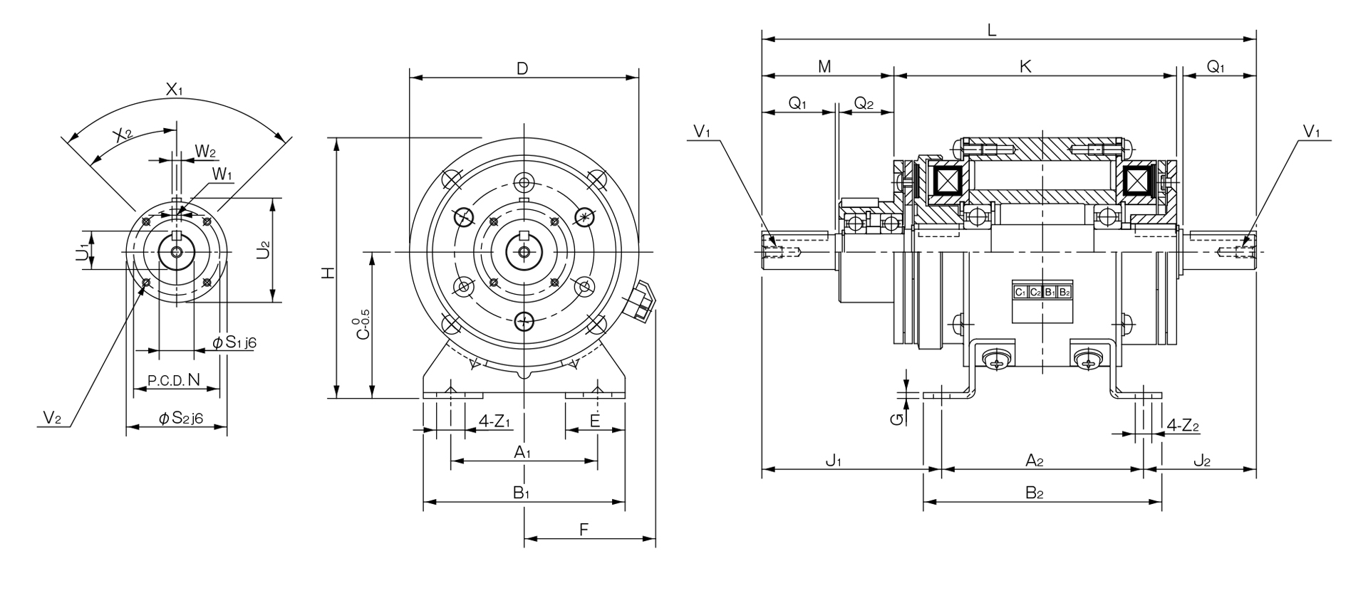
Unit [mm]
| Size | Unit Dimensions | Shaft Dimensions | |||||||||||||||||||||||||||
|---|---|---|---|---|---|---|---|---|---|---|---|---|---|---|---|---|---|---|---|---|---|---|---|---|---|---|---|---|---|
| A1 | A2 | B1 | B2 | C | D | E | F | G | H | J1 | J2 | K | L | M | N | Z1 | Z2 | Q1 | Q2 | S1 | S2 | U1 | U2 | V1 | V2 | X1 | X2 | W1,2 | |
| 6 | 52.5 | 75 | 80 | 90 | 55 | 80 | 27.5 | 53 | 2.6 | 95 | 65.5 | 40.5 | 105.5 | 181 | 47 | 33 | 13.5 | 6.5 | 25 | 20 | 11 | 38 | 12.5 | 39.5 | M4×0.7, depth 8 | 3-M4×0.7 depth 4 | 3-120° | 60° | 4 |
| 8 | 65 | 90 | 90 | 105 | 65 | 100 | 27.5 | 61 | 2.6 | 115 | 78.5 | 48.5 | 126.5 | 217 | 57 | 37 | 13.5 | 6.5 | 30 | 25 | 14 | 45 | 16 | 47 | M4×0.7, depth 8 | 3-M4×0.7 depth 6 | 3-120° | 60° | 5 |
| 10 | 80 | 110 | 110 | 130 | 80 | 125 | 32.5 | 72 | 3.2 | 142.5 | 98 | 62 | 154 | 270 | 72 | 47 | 15.5 | 9 | 40 | 30 | 19 | 55 | 21 | 57 | M6×1, depth 11 | 4-M4×0.7, depth 8 | 4-90° | 45° | 5 |
| 12 | 105 | 135 | 140 | 160 | 90 | 150 | 35 | 81 | 3.2 | 165 | 121 | 73.5 | 184 | 330 | 92 | 52 | 20 | 11.5 | 50 | 40 | 24 | 64 | 27 | 67 | M6×1, depth 11 | 4-M4×0.7 depth 8 | 4-90° | 45° | 7 |
| 16 | 135 | 160 | 175 | 185 | 112 | 190 | 43 | 97 | 4.5 | 207 | 149 | 90 | 221 | 399 | 113 | 62 | 24.5 | 11.5 | 60 | 50 | 28 | 75 | 31 | 78 | M6×1, depth 11 | 6-M5×0.8 depth 8 | 6-60° | 30° | 7 |
| 20 | 155 | 200 | 200 | 230 | 132 | 230 | 45 | 109 | 6 | 247 | 187 | 117 | 276 | 504 | 142 | 74.5 | 28 | 14 | 80 | 60 | 38 | 90 | 41.5 | 93.5 | M10×1.5, depth 17 | 4-M6×1, depth 12 | 4-90° | 45° | 10 |
| 25 | 195 | 240 | 240 | 270 | 160 | 290 | 47.5 | 124 | 20 | 305 | 238 | 154 | 334 | 632 | 183 | 101.5 | 28 | 14 | 110 | 70 | 42 | 115 | 45.5 | 118.5 | M10×1.5, depth 17 | 8-M6×1, depth 12 | 8-45° | 22.5° | 12 |
- The keyways on the input and output shafts comply with the old JIS Type 2 standard, while the keys comply with the old JIS Type 1 standard. Please note that the keyway dimensions for the unit hub section do not comply with JIS standards. Please refer to the dimension table above.
- When installing pulleys or similar components on the input or output shafts, please use the included installation kit.
- The base of the 121-25-20G is made of cast metal.