Model 125 (Housing-Integrated Type_Clutch and Brake Unit)
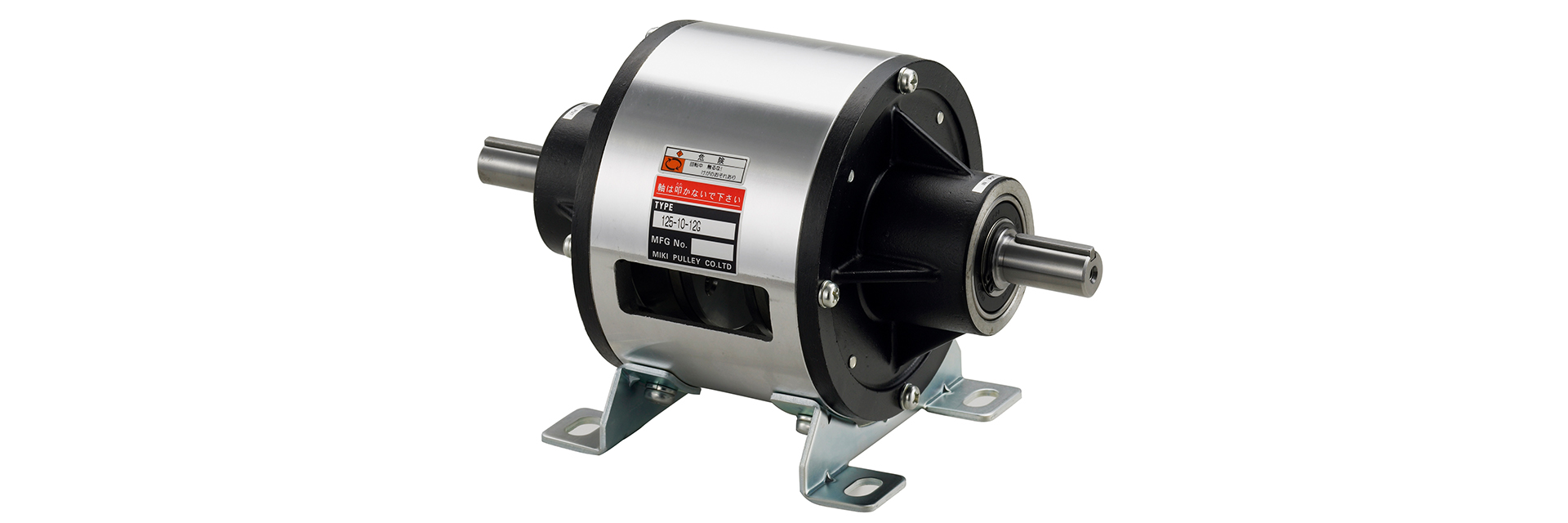
This is a splash-proof electromagnetic clutch and brake unit that houses an electromagnetic clutch and an electromagnetic brake in a light alloy housing using a coaxial shaft configuration.Power is supplied via the input shaft and is constantly output via the output shaft. The output shaft is braked by energizing the brake when the clutch current is interrupted. Mounting brackets are available for selection.
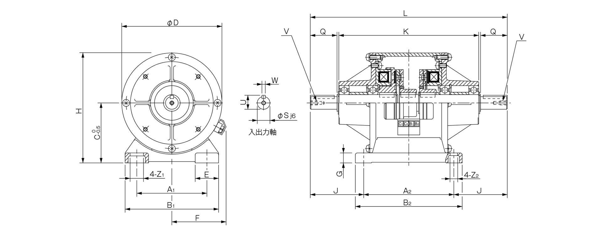
[Specifications] Steel plate base
| Model | Size | Dynamic friction torque Td [N·m] | Static friction torque Ts [N·m] | Coil (at 20°C) | Temperature Class | Maximum rotational speed [min⁻¹] | Rotating mass moment of inertia J [kg·m²] | Total work until air gap readjustment ET [J] | |||
|---|---|---|---|---|---|---|---|---|---|---|---|
| Voltage [V] | Power [W] | Current [A] | Resistance [Ω] | ||||||||
| 125-05-12G | 05 | 2.4 | - | DC24 | 10 | 0.42 | 58 | B | 3000 | 2.4×10⁻⁵ | 9×10⁶ |
| 125-06-12G | 06 | 5 | 5.5 | DC24 | 11 | 0.46 | 52 | B | 3000 | 1.28×10⁻⁴ | 36×10⁶ |
| 125-08-12G | 08 | 10 | 11 | DC24 | 15 | 0.63 | 38 | B | 3000 | 3.70×10⁻⁴ | 60×10⁶ |
| 125-10-12G | 10 | 20 | 22 | DC24 | 20 | 0.83 | 29 | B | 3000 | 1.40×10⁻³ | 130×10⁶ |
| 125-12-12G | 12 | 40 | 45 | DC24 | 25 | 1.04 | 23 | B | 3000 | 3.85×10⁻³ | 250×10⁶ |
| 125-16-12G | 16 | 80 | 90 | DC24 | 35 | 1.46 | 16 | B | 3000 | 1.35×10⁻² | 470×10⁶ |
- The dynamic friction torque Td is the value at a relative speed of 100 min⁻¹. Additionally, depending on the initial torque characteristics, a break-in period may be required.
[Dimensions] 125-05-12G
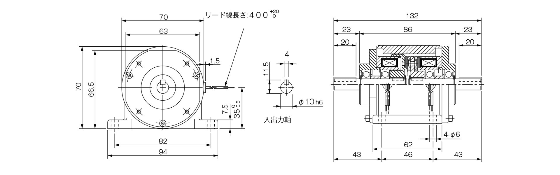
[Dimensions] 125-□-12G (steel plate base)
Unit [mm]
| Size | Unit Dimensions | Shaft Dimensions | ||||||||||||||||||
|---|---|---|---|---|---|---|---|---|---|---|---|---|---|---|---|---|---|---|---|---|
| A1 | A2 | B1 | B2 | C | D | E | F | G | H | J | K | L | Z1 | Z2 | Q | S | U | V | W | |
| 06 | 65 | 90 | 90 | 105 | 65 | 100 | 27.5 | 61 | 2.6 | 115 | 48.5 | 132 | 187 | 13.5 | 6.5 | 25 | 11 | 12.5 | M4×0.7, depth 8 | 4 |
| 08 | 80 | 110 | 110 | 130 | 80 | 125 | 32.5 | 72 | 3.2 | 142.5 | 63 | 171 | 236 | 15.5 | 9 | 30 | 14 | 16 | M4×0.7, depth 8 | 5 |
| 10 | 105 | 135 | 140 | 160 | 90 | 150 | 35 | 81 | 3.2 | 165 | 80 | 210 | 295 | 20 | 11.5 | 40 | 19 | 21 | M6×1, depth 11 | 5 |
| 12 | 135 | 160 | 175 | 185 | 112 | 190 | 42.5 | 97 | 4.5 | 207 | 108 | 270 | 376 | 24.5 | 11.5 | 50 | 24 | 27 | M6×1, depth 11 | 7 |
| 16 | 155 | 200 | 200 | 230 | 132 | 230 | 45 | 109 | 6 | 247 | 145 | 362 | 490 | 28 | 14 | 60 | 28 | 31 | M6×1, depth 11 | 7 |
- The keyways on the input and output shafts comply with the old JIS Type 2 standard, and the keys comply with the old JIS Type 1 standard.
- When installing pulleys or similar components on the input or output shafts, please use the included installation kit.

[Specifications] 125-□-12EG (Cast iron base) *Made to order
| Model | Size | Dynamic friction torque Td [N·m] | Static friction torque Ts [N·m] | Coil (at 20°C) | Temperature Class | Maximum rotational speed [min⁻¹] | Rotating mass moment of inertia J [kg·m²] | Total work until air gap readjustment ET [J] | Armature pull-in time ta [s] | Torque rise time tp [s] | Torque decay time td [s] | Mass [kg] | |||
|---|---|---|---|---|---|---|---|---|---|---|---|---|---|---|---|
| Voltage [V] | Power [W] | Current [A] | Resistance [Ω] | ||||||||||||
| 125-06-12EG | 06 | 5 | 5.5 | DC24 | 11 | 0.46 | 52 | B | 3000 | 1.28×10⁻⁴ | 36×10⁶ | C: 0.020 / B: 0.015 | C: 0.041 / B: 0.033 | C: 0.020 / B: 0.015 | 2.1 |
| 125-08-12EG | 08 | 10 | 11 | DC24 | 15 | 0.63 | 38 | B | 3000 | 3.70×10⁻⁴ | 60×10⁶ | C: 0.023 / B: 0.016 | C: 0.051 / B: 0.042 | C: 0.030 / B: 0.025 | 4.2 |
| 125-10-12EG | 10 | 20 | 22 | DC24 | 20 | 0.83 | 29 | B | 3000 | 1.40×10⁻³ | 130×10⁶ | C: 0.025 / B: 0.018 | C: 0.063 / B: 0.056 | C: 0.050 / B: 0.030 | 6.8 |
| 125-12-12EG | 12 | 40 | 45 | DC24 | 25 | 1.04 | 23 | B | 3000 | 3.85×10⁻³ | 250×10⁶ | C: 0.040 / B: 0.027 | C: 0.115 / B: 0.090 | C:0.065 / B:0.050 | 12 |
| 125-16-12EG | 16 | 80 | 90 | DC24 | 35 | 1.46 | 16 | B | 3000 | 1.35×10⁻² | 470×10⁶ | C: 0.050 / B: 0.035 | C: 0.160 / B: 0.127 | C:0.085 / B:0.055 | 22 |
| 125-20-12EG | 20 | 160 | 175 | DC24 | 45 | 1.86 | 13 | B | 2500 | 4.08×10⁻² | 10×10⁵ | C: 0.090 B: 0.065 | C: 0.250 B: 0.207 | C:0.130 B:0.070 | 49 |
- The dynamic friction torque Td is the value at a relative speed of 100 min⁻¹. Additionally, depending on the initial torque characteristics, a break-in period may be required.
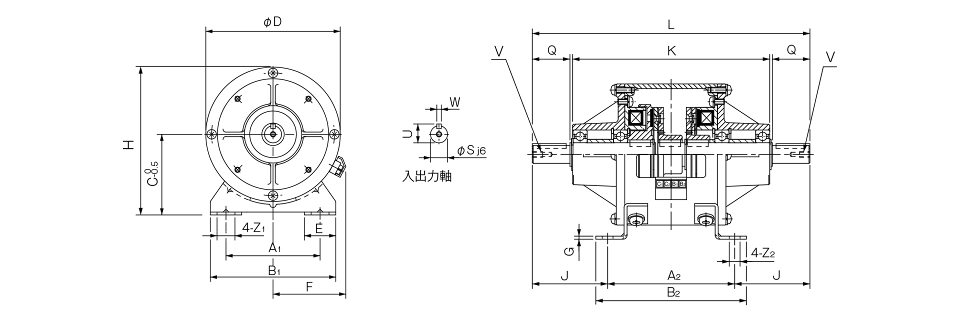
[Dimensions] 125-□-12EG (Cast iron base) *Made to order
Unit [mm]
| Size | Unit Dimensions | Shaft Dimensions | ||||||||||||||||||
|---|---|---|---|---|---|---|---|---|---|---|---|---|---|---|---|---|---|---|---|---|
| A1 | A2 | B1 | B2 | C | D | E | F | G | H | J | K | L | Z1 | Z2 | Q | S | U | V | W | |
| 06 | 65 | 90 | 90 | 105 | 65 | 100 | 27.5 | 61 | 10 | 115 | 48.5 | 132 | 187 | 13.5 | 6.5 | 25 | 11 | 12.5 | M4×0.7, depth 8 | 4 |
| 08 | 80 | 110 | 110 | 130 | 80 | 125 | 32.5 | 72 | 12 | 142.5 | 63 | 171 | 236 | 15.5 | 9 | 30 | 14 | 16 | M4×0.7, depth 8 | 5 |
| 10 | 105 | 135 | 140 | 160 | 90 | 150 | 35 | 81 | 15 | 165 | 80 | 210 | 295 | 20 | 11.5 | 40 | 19 | 21 | M6×1, depth 11 | 5 |
| 12 | 135 | 160 | 175 | 185 | 112 | 190 | 42.5 | 97 | 15 | 207 | 108 | 270 | 376 | 24.5 | 11.5 | 50 | 24 | 27 | M6×1, depth 11 | 7 |
| 16 | 155 | 200 | 200 | 230 | 132 | 230 | 45 | 109 | 18 | 247 | 145 | 362 | 490 | 28 | 14 | 60 | 28 | 31 | M6×1, depth 11 | 7 |
| 20 | 195 | 240 | 240 | 270 | 160 | 290 | 47.5 | 124 | 20 | 305 | 188 | 448 | 616 | 28 | 14 | 80 | 38 | 41.5 | M10×1.5, depth 17 | 10 |
- The keyways on the input and output shafts comply with the old JIS Type 2 standard, and the keys comply with the old JIS Type 1 standard.
- When installing pulleys or similar components on the input or output shafts, please use the included installation kit.