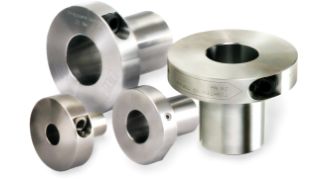
Learning Mechanical Components from Scratch: What Is an ETP Bushing?
2026/06/15

What is an ETP bushing (friction-type fastener/hydraulic type)?
This mechanical component utilizes Pascal's principle to enable high-precision mounting with a single bolt. Also
known as a friction-type fastener, it performs functions equivalent to or better than those of Posilock. It is widely used
in machine tools, semiconductor manufacturing equipment, food processing machinery, and other applications.
*For more details, click here →
The Role of ETP Bushings (Friction-Type Fasteners/Hydraulic Type)
This fastening element was developed to address the challenges associated with conventional fastening methods, such as keys and set screws.
It is also known as a keyless bushing.
*For more details, click here →
■Challenges Facing Key and Set Services
■The Issue of the Axis
The shaft requires keyways or flat-facing. Over time, the shaft may become scratched, or it may experience wear or seizure.

■Accuracy Issues
Due to the difficulty in aligning the phases and poor rotational balance, backlash may occur.
■Vibration Issues
Vibration and other factors can cause keys to fall out or retaining screws to loosen, so anti-loosening devices are necessary.
Features and Structure of ETP Bushings (Friction-Type Fasteners / Hydraulic Type)
*For more details, click here →
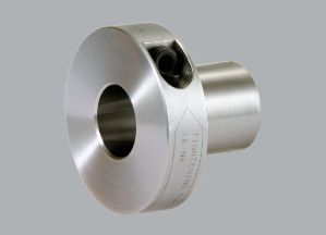
ETP-E Plus
The shaft and hub can be easily and quickly secured with a single bolt. Furthermore, with an excellent concentricity of 0.02 mm, this solution is ideal for applications requiring high precision and frequent assembly and disassembly. Since the structure is tightened radially, it does not require much working space.
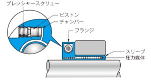
Principle of Operation
The pressurized medium sealed within the chamber is pressurized by tightening the pressure screw and flows into the sleeve. As a result of this pressurization, the sleeve is subjected to internal pressure, causing the shaft-side sleeve to contract and the hub-side sleeve to expand, thereby securing the shaft and hub together via the sleeve.
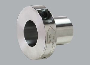
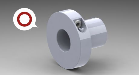
ETP-T
The shaft and hub can be easily and quickly secured with a single bolt. Furthermore, with an excellent concentricity of 0.006 mm, this solution is ideal for applications requiring high precision and frequent assembly and disassembly. Since the structure is tightened radially, it does not require much working space.
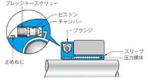
Principle of Operation
The pressurized medium enclosed within the chamber is pressurized by tightening the pressure screw and flows into the sleeve. As a result of this pressurization, the sleeve is subjected to internal pressure, causing the shaft-side sleeve to contract and the hub-side sleeve to expand, thereby securing the shaft and hub together via the sleeve.
Precautions for Using ETP Bushings (Friction-Type Fasteners/Hydraulic Type)
Precautions for the Manufacturing Site
1. Do not remove the pressure screw or set screw (ETP-T only).
Oil leaks or changes in internal fluid pressure may occur, preventing proper tightening.
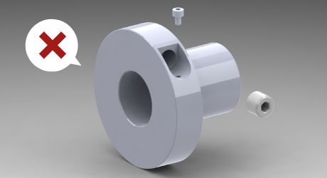
[NG] Complete removal of screws
2. Do not tighten the screw.
The inner diameter may become deformed, making it impossible to install.
[NG] The shaft or hub is not inserted (loose fit)
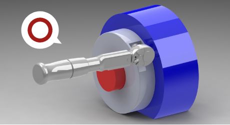
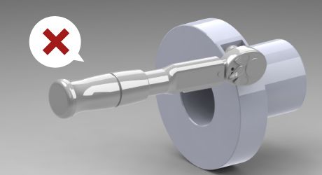
3. Use a calibrated torque wrench.
Using tools without torque ratings (such as L-wrenches) can result in excessive tightening torque, which may damage the ETP.
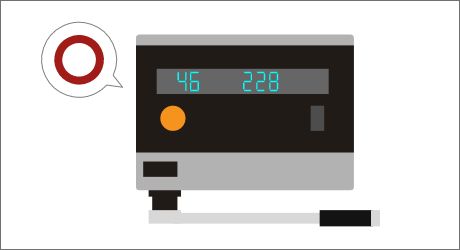
Check the tightening torque and install the part using a torque wrench that has been calibrated with a torque checker.
ETP - E Plus
Pressure Screw Tightening Torque Chart / Permissible Mounting Dimensions at Ends (Permissible Length S)
- Even if the types are different, the tightening torque will be the same if the sizes are identical.
- The inner diameter tolerance for the mounting hub is "H7" for all sizes.
[How to Read Model Numbers]

| Size | Type | Nominal Diameter | Face-to-face dimension [mm] | Tightening Torque [N·m] | Permissible Length S [mm] | ||||
|---|---|---|---|---|---|---|---|---|---|
| ETP-E-015 | NH | CH | RH | - | - | M10 | 5 | 7 | 2 |
| ETP-E-019 | NH | CH | - | NK | CK | M10 | 5 | 7 | 2 |
| ETP-E-020 | NH | CH | RH | - | - | M10 | 5 | 7 | 2 |
| ETP-E-022 | NH | CH | - | NK | CK | M10 | 5 | 7 | 3 |
| ETP-E-025 | NH | CH | RH | - | - | M10 | 5 | 7 | 3 |
| ETP-E-028 | NH | CH | - | NK | CK | M10 | 5 | 7 | 4 |
| ETP-E-030 | NH | CH | RH | - | - | M10 | 5 | 7 | 4 |
| ETP-E-032 | NH | CH | - | NK | CK | M10 | 5 | 7 | 4 |
| ETP-E-035 | NH | CH | RH | - | - | M10 | 5 | 7 | 4 |
| ETP-E-038 | NH | CH | - | NK | CK | M16 | 8 | 24 | 5 |
| ETP-E-040 | NH | CH | RH | - | - | M16 | 8 | 24 | 5 |
| ETP-E-042 | NH | CH | - | NK | CK | M16 | 8 | 24 | 5 |
| ETP-E-045 | NH | CH | RH | - | - | M16 | 8 | 24 | 5 |
| ETP-E-048 | NH | CH | - | NK | CK | M16 | 8 | 24 | 5 |
| ETP-E-050 | NH | CH | RH | - | - | M16 | 8 | 24 | 5 |
| ETP-E-055 | NH | CH | - | NK | CK | M16 | 8 | 24 | 5 |
| ETP-E-060 | NH | CH | RH | - | - | M16 | 8 | 24 | 5 |
| ETP-E-070 | NH | - | - | - | - | M20 | 10 | 40 | 8 |
| ETP-E-080 | NH | - | - | - | - | M20 | 10 | 40 | 8 |
| ETP-E-090 | NH | - | - | - | - | M20 | 10 | 40 | 8 |
| ETP-E-100 | NH | - | - | - | - | M20 | 10 | 40 | 8 |
ETP-T
Pressure Screw Tightening Torque Chart / Permissible Mounting Dimensions at Ends (Permissible Length S)
- Even if the types are different, the tightening torque will be the same if the sizes are identical.
- The inner diameter tolerance for the mounting hub is "H7" for all sizes.
[How to Read Model Numbers]

| Size | Type | Nominal Diameter | Face-to-face dimension [mm] | Tightening Torque [N·m] | Permissible Length S [mm] | |
|---|---|---|---|---|---|---|
| ETP-T-15 | Not specified | C | M12 | 6 | 12 | 5 |
| ETP-T-19 | No designation | C | M12 | 6 | 12 | 5 |
| ETP-T-20 | No designation | C | M12 | 6 | 12 | 5 |
| ETP-T-24 | No designation | C | M14 | 6 | 12 | 5 |
| ETP-T-25 | No designation | C | M14 | 6 | 12 | 6 |
| ETP-T-30 | No designation | C | M14 | 6 | 12 | 6 |
| ETP-T-35 | No designation | C | M14 | 6 | 12 | 6 |
| ETP-T-40 | No designation | C | M16 | 8 | 24 | 7 |
| ETP-T-50 | No designation | C | M16 | 8 | 24 | 8 |
| ETP-T-60 | No designation | C | M20 | 10 | 40 | 9 |
| ETP-T-70 | No designation | - | M20 | 10 | 40 | 10 |
| ETP-T-75 | No designation | - | M20 | 10 | 40 | 10 |
| ETP-T-80 | No designation | - | M20 | 10 | 40 | 10 |
| ETP-T-90 | No designation | - | M22 | 10 | 60 | 10 |
| ETP-T-100 | No designation | - | M24 | 12 | 80 | 10 |
4. Please use the product in accordance with the recommended number of times it can be put on and taken off.
The number of times the product can be put on and taken off varies by product. Please refer to the table below.
| Model | Number of insertions/removals (times) | |
|---|---|---|
| ETP-E(N) | ETP-E-015-N to 035-N | 3000 |
| ETP-E-038-N~060-N | 2000 | |
| ETP-E-070-N~100-N | 750 | |
| ETP-E(C) | ETP-E-015-C~035-C | 1500 |
| ETP-E-038-C~060-C | 1000 | |
| ETP-E(R) | ETP-E-015-R~035-R | 1200 |
| ETP-E-040-R~060-R | 600 | |
| ETP-T | ETP-T-15~50 | 5000 |
| ETP-T-60~80 | 3000 | |
| ETP-T-90*100 | 500 | |
| ETP-T(C) | ETP-T-15-C to 50-C | 5000 |
| ETP-T-60-C | 3000 | |
When installing or removing the component, prevent foreign matter from adhering to the pressure screw, and ensure that oils or greases containing molybdenum-based, silicone-based, or fluorine-based anti-friction agents are always applied to the surface of the pressure screw.
Design Considerations
5. Check the allowable radial load.
If a radial load (longitudinal force) exceeding the specified limit is applied, the ETP may be damaged.
Please check the tolerance values on the product specifications page.
*For more details, click here →
An extreme example of something that is easily damaged
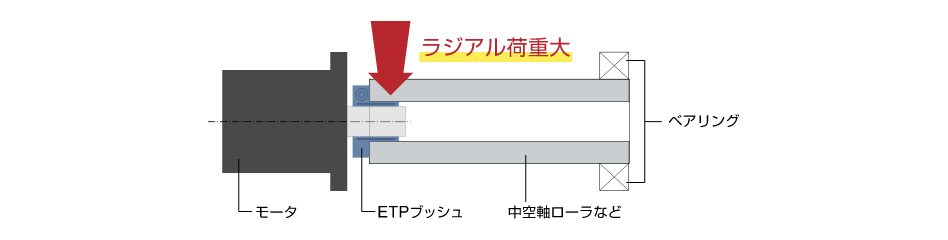
The skewing force caused by misalignment between the motor's output shaft and the hollow shaft roller (support bearing) is transmitted to the ETP bushing as an excessive radial load.
6. Check the insertion depth of the shaft.
If the shaft and hub are not inserted far enough, this may cause the ETP to deform or slip.
Please design the hub (gear, pulley, etc.) so that pressure is applied evenly, using the insertion values below as a reference.
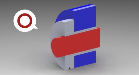
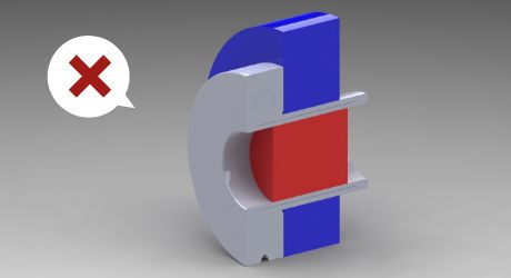
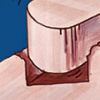
[NG] The shaft (red) and hub (blue) are not in full contact
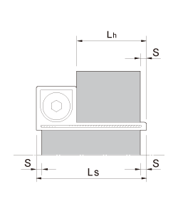
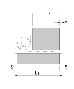
・Tolerance range at the ends
The product performance specifications apply when the shaft and hub are engaged along their entire length relative to the shaft-side reference dimension LS and the hub-side reference dimension Lh. Therefore, please design the shaft and hub so that they engage along their entire length relative to these reference dimensions.If the length of the shaft or hub is limited by design, ensure that it does not exceed the dimension S shown in the figure below. If the dimension S is exceeded, stress will concentrate at the sleeve end, causing the sleeve to deform and making removal impossible.
Details
| ETP-E Plus Size | S [mm] | |
|---|---|---|
 | 015 | 2 |
| 019 | 2 | |
| 020 | 2 | |
| 2022 | 3 | |
| 2024 | 3 | |
| 025 | 3 | |
| 028 | 4 | |
| 030 | 4 | |
| 032 | 4 | |
| 035 | 4 | |
| 038 | 5 | |
| 040 | 5 | |
| 042 | 5 | |
| 045 | 5 | |
| 048 | 5 | |
| 050 | 5 | |
| 055 | 5 | |
| 060 | 5 | |
| 070 | 8 | |
| 080 | 8 | |
| 090 | 8 | |
| 100 | 8 | |
| ETP-T Size | S [mm] | |
|---|---|---|
 | 15 | 5 |
| 19 | 5 | |
| 20 | 5 | |
| 24 | 5 | |
| 25 | 6 | |
| 30 | 6 | |
| 35 | 6 | |
| 40 | 7 | |
| 50 | 8 | |
| 60 | 9 | |
| 70 | 10 | |
| 75 | 10 | |
| 80 | 10 | |
| 90 | 10 | |
| 100 | 10 | |
| - | - | |
| - | - | |
| - | - | |
| - | - | |
| - | - | |
| - | - | |
| - | - | |
7. Please select products with the correct shaft tolerance.
If the [shaft diameter and tolerance] and [hub bore diameter and tolerance] do not match, the product cannot be installed correctly. Please check the shaft tolerance when selecting the product.
・Mounting shaft tolerances, mounting hub tolerances, and surface roughness
| Model | Mounting Shaft Tolerance | Mounting Hub Tolerance | Surface roughness | |
| ETP-EPlus | ETP-E-□-NH・CH・RH | h7 (g6・h6) | H7 | 25S (average roughness along the centerline 6.3a or less) |
| ETP-E-□-NK・CK | k6 (j6) | |||
| ETP-T | ETP-T-□ | h8 | ||
| ETP-T-□-C | ||||