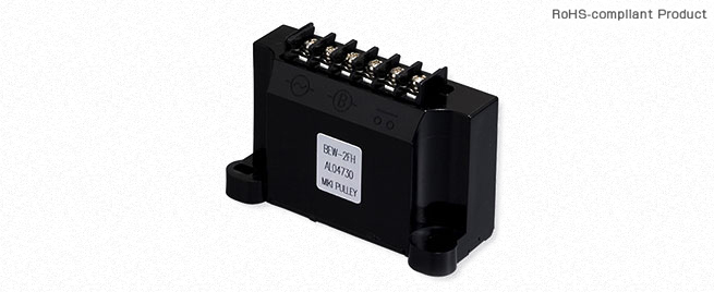
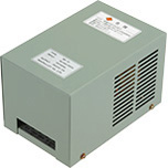
| Model | BEW-1FH | BEW-2FH | BEW-4FH |
|---|
| Input voltage | 100 V AC | ± 10% 50/60 Hz | ● | ● | | | | |
|---|
| 200 V AC | | | ● | ● | | |
| 400 V AC | | | | | ● | ● |
| Input voltage range | AC80 ~ 130V | AC170 ~ 300V | AC80 ~ 480V |
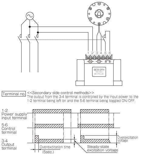
| Control method | Overexcitation (full-wave rectified) for 0.5 sec followed by constant excitation (half-wave rectified) |
|---|
| Overexcitation | Constant excitation | Overexcitation | Constant excitation | Overexcitation | Constant excitation |
| Output voltage | DC90V | DC45V | DC180V | DC90V | DC360V | DC180V |
|---|
| Output current | When the ambient temperature is 20℃ values in () are for an ambient temperature of 60℃ | DC1.6A (DC1.3A) Constant excitation | 1.2 A DC (1.0 A DC) Constant excitation |
|---|
| Output capacity | When the ambient temperature is 20℃ values in () are for an ambient temperature of 60℃ | 72 W (58 W) Constant excitation | 144 W (117 W) Constant excitation | 216 W (180 W) Constant excitation |
|---|
| Size settings | Purpose for use | Using overexcitation | Using weak excitation | Using overexcitation | Using weak excitation | Using overexcitation | Using weak excitation |
|---|
| Clutch/brake rated voltage | DC45V | DC90V | DC90V | DC180V | DC180V | DC360V |
| ●: Applicable | 01 | ● | ● | ● | ● | ● | |
| 02 | ● | ● | ● | ● | ● | |
| 03 | ● | ● | ● | ● | ● | |
| 04 | ● | ● | ● | ● | ● | |
| 05 | ● | ● | ● | ● | ● | |
| 06 | ● | ● | ● | ● | ● | |
| 08 | ● | ● | ● | ● | ● | |
| 10 | ● | ● | ● | ● | ● | |
| 12 | | ● | ● | ● | ● | |
| 14 | | ● | ● | ● | ● | |
| 16 | | ● | ● | ● | ● | |
| 18 | | ● | ● | ● | ● | |
| 20 | | ● | ● | ● | ● | |
| 25 | | ● | ● | ● | ● | |
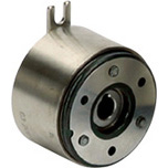
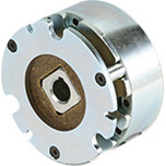
| Applied cutches/brakes | MIKI PULLEY electromagnetic-actuated
clutches and brakes Rated voltage DC 45/90/180 V | Spring-actuated brake |
|---|
| Insulating resistance | Between terminal and body | DC 500 V, 100 M Ω with Megger |
|---|
| 2000 V AC, 50 Hz, 1 min. |
| Usage environment | With no condensation | -20℃ ~ +60℃ |
|---|
| Mass | Per product | 0.065 kg |
|---|
[Characteristics]
Used as Overexcitation Supplies
BEW(FH) models go through about 0.5 sec of full-wave rectified output and then transition to half-wave rectified output. BEW-FH power supply devices create an overexcitation state by matching their constant excitation voltage to the rated voltage of the electromagnetic clutch/brake to obtain the following effects.
• Longer electromagnetic clutch/brake service life (about double)
• Shorter armature pull-in time (about half) to achieve high frequency operation
• Longer service life (about double)
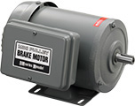
• Reduced startup interference by combined use of a spring-actuated brake and a motor
Also, the following effects can also be obtained by determining the specifications of the spring-actuated brake under the assumption that a BEW-FH power supply will be used.
• Higher torque
• Thinner design and lighter weight
Use as a weak excitation power supply
Conversely to the above, matching the overexcitation voltage of the power supply unit to the rated voltage of the electromagnetic clutch and brake produces a weak excitation state after suctioning the armature and generates the below effects.
• Reduced power consumption (by approx. one-fourth)
• Decreased generation of heat (by approx. one-fourth) by the stator (electromagnetic coil)
• Slimmer and more compact
 日本語
日本語 English
 Deutsch
 中文
中文 한국어
한국어