日本語
日本語 English
 Deutsch
 中文
中文 한국어
한국어


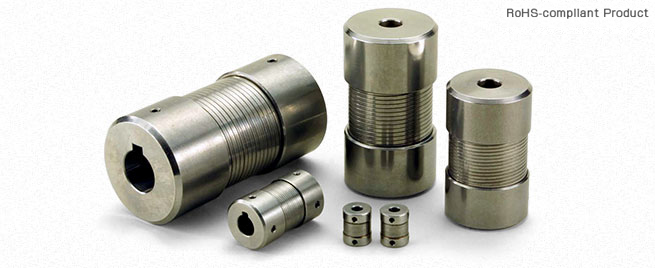
MM Models

![]()
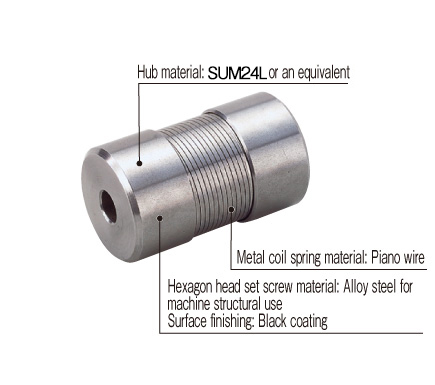
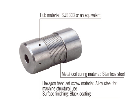
MM Models
[Specifications]
| Model | Rated Torque [N・m] | Misalignment | Max. rotation speed [min-1] | Torsional stiffness [N・m/rad] | Moment of inertia [kg・m2] | Mass [kg] | ||
|---|---|---|---|---|---|---|---|---|
| Parallel [mm] | Angular [°] | Axial [mm] | ||||||
| MM-6K | 2.5 | 0.3 | 3 | +0.6 | 20000 | 143 | 7.65×10⁻⁷ | 0.03 |
| MM-8K | 5 | 0.3 | 3 | +0.8 | 15000 | 286.5 | 4.08×10⁻⁶ | 0.07 |
| MM-12K | 10 | 0.4 | 3 | +1.0 | 12000 | 573 | 1.43×10⁻⁵ | 0.14 |
| MM-14K | 10 | 0.5 | 3 | +1.0 | 10000 | 573 | 2.47×10⁻⁵ | 0.15 |
| MM-16K | 20 | 0.6 | 3 | +1.2 | 9000 | 1146 | 6.12×10⁻⁵ | 0.30 |
| MM-19K | 20 | 0.7 | 3 | +1.2 | 8000 | 1146 | 8.42×10⁻⁵ | 0.32 |
| MM-20K | 40 | 0.7 | 3 | +1.6 | 7000 | 2292 | 1.99×10⁻⁴ | 0.70 |
| MM-24K | 40 | 0.9 | 3 | +1.6 | 7000 | 2292 | 2.63×10⁻⁴ | 0.75 |
| MM-25K | 90 | 0.9 | 3 | +2.0 | 6000 | 3438 | 5.66×10⁻⁴ | 1.25 |
| MM-28K | 90 | 1.0 | 3 | +2.0 | 6000 | 2865 | 5.77×10⁻⁴ | 1.35 |
| MM-30K | 150 | 1.1 | 3 | +2.5 | 5000 | 4297.5 | 1.39×10⁻⁴ | 2.10 |
| MM-35K | 220 | 1.2 | 3 | +3.2 | 4500 | 6303 | 3.01×10⁻⁴ | 3.50 |
| Model | Rated Torque [N・m] | Misalignment | Max. rotation speed [min-1] | Torsional stiffness [N・m/rad] | Moment of inertia [kg・m2] | Mass [kg] | ||
|---|---|---|---|---|---|---|---|---|
| Parallel [mm] | Angular [°] | Axial [mm] | ||||||
| MM-6K-S | 2.5 | 0.3 | 3 | +0.6 | 20000 | 143 | 7.65×10⁻⁷ | 0.03 |
| MM-8K-S | 5 | 0.3 | 3 | +0.8 | 15000 | 286.5 | 4.08×10⁻⁶ | 0.07 |
| MM-12K-S | 10 | 0.4 | 3 | +1.0 | 12000 | 573 | 1.43×10⁻⁵ | 0.14 |
| MM-16K-S | 20 | 0.6 | 3 | +1.2 | 9000 | 1146 | 6.12×10⁻⁵ | 0.30 |
| MM-20K-S | 40 | 0.7 | 3 | +1.6 | 7000 | 2292 | 1.99×10⁻⁴ | 0.70 |
| MM-25K-S | 90 | 0.9 | 3 | +2.0 | 6000 | 3438 | 5.66×10⁻⁴ | 1.25 |
*Max. rotation speed does not take into account dynamic balance.
*The moment of inertia and mass are measured for the maximum bore diameter.
[Dimensions]

| Model | d1, d2 | D | L | L1 | E | F | ||
|---|---|---|---|---|---|---|---|---|
| Pilot bore | Min. | Max. | ||||||
| MM-6K | 2.5 | 3 | 8 | 16 | 20 | 6 | 11 | 15.5 |
| MM-8K | 3.5 | 4 | 8 | 21 | 35 | 11 | 13 | 19 |
| MM-12K | 5.5 | 6 | 12 | 26 | 50 | 16.5 | 16.5 | 24 |
| MM-14K | 5.5 | 7 | 14 | 30 | 50 | 16.5 | 20.5 | 28 |
| MM-16K | 5.5 | 10 | 16 | 35 | 65 | 22 | 22.4 | 32 |
| MM-19K | 5.5 | 10 | 19 | 38 | 65 | 22 | 26.4 | 36 |
| MM-20K | 5.5 | 10 | 20 | 45 | 80 | 27 | 28 | 40 |
| MM-24K | 5.5 | 14 | 24 | 48 | 80 | 27 | 33 | 45 |
| MM-25K | 5.5 | 14 | 25 | 55 | 100 | 33.5 | 35 | 50 |
| MM-28K | 5.5 | 14 | 28 | 55 | 100 | 33.5 | 37 | 52 |
| MM-30K | 5.5 | 16 | 30 | 65 | 125 | 40 | 40.8 | 60 |
| MM-35K | 5.5 | 20 | 35 | 75 | 150 | 48 | 46 | 70 |
| Model | d1, d2 | D | L | L1 | E | F | ||
|---|---|---|---|---|---|---|---|---|
| Pilot bore | Min. | Max. | ||||||
| MM-6K-S | 2.5 | 3 | 8 | 17 | 25 | 9 | 11 | 15.5 |
| MM-8K-S | 3.5 | 4 | 8 | 21 | 35 | 11 | 13 | 19 |
| MM-12K-S | 5.5 | 6 | 12 | 26 | 50 | 16.5 | 16.5 | 24 |
| MM-16K-S | 5.5 | 10 | 16 | 35 | 65 | 22 | 22.4 | 32 |
| MM-20K-S | 5.5 | 10 | 20 | 45 | 80 | 27 | 28 | 40 |
| MM-25K-S | 5.5 | 14 | 25 | 55 | 100 | 32.5 | 35 | 50 |
*Pilot bores are to be drilled into the part.

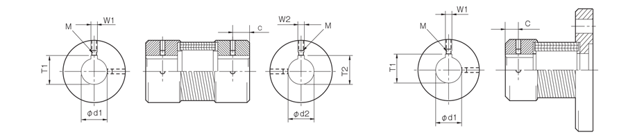
[Standard Hole-drilling Standards]
| Models compliant with the old JIS standard (class 2) JIS B 1301 1959 | Models compliant with the new JIS standard (H9) JIS B 1301 1996 | Models compliant with the new JIS standard (JS9) JIS B 1301 1996 | Models compliant with the motor standard JIS C 4210 2001 | ||||||||||||||||
|---|---|---|---|---|---|---|---|---|---|---|---|---|---|---|---|---|---|---|---|
| Nominal bore diameter | Bore diameter [d1・d2] | Keyway width [W1・W2] | Keyway height [T1・T2] | Set screw hole [M] | Nominal bore diameter | Bore diameter [d1・d2] | Keyway width [W1・W2] | Keyway height [T1・T2] | Set screw hole [M] | Nominal bore diameter | Bore diameter [d1・d2] | Keyway width [W1・W2] | Keyway height [T1・T2] | Set screw hole [M] | Nominal bore diameter | Bore diameter [d1・d2] | Keyway width [W1・W2] | Keyway height [T1・T2] | Set screw hole [M] |
| Tolerance H7,H8 | Tolerance E9 | - | Tolerance H7 | Tolerance H9 | - | Tolerance H7 | Tolerance JS9 | - | Tolerance G7,F7 | Tolerance H9 | - | ||||||||
| 4 | 4+0.0180 | - | - | 2-M3 | - | - | - | - | - | - | - | - | - | - | - | - | - | - | - |
| 5 | 5+0.0180 | - | - | 2-M3 | - | - | - | - | - | - | - | - | - | - | - | - | - | - | - |
| 6 | 6+0.0180 | - | - | 2-M4 | - | - | - | - | - | - | - | - | - | - | - | - | - | - | - |
| 6.35 | 6.35+0.0220 | - | - | 2-M4 | - | - | - | - | - | - | - | - | - | - | - | - | - | - | - |
| 7 | 7+0.0220 | - | - | 2-M4 | - | - | - | - | - | - | - | - | - | - | - | - | - | - | - |
| 8 | 8+0.0220 | - | - | 2-M4 | - | - | - | - | - | - | - | - | - | - | - | - | - | - | - |
| 9 | 9+0.0220 | - | - | 2-M4 | - | - | - | - | - | - | - | - | - | - | - | - | - | - | - |
| 9.5 | 9.5+0.0220 | - | - | 2-M4 | - | - | - | - | - | - | - | - | - | - | - | - | - | - | - |
| 9.525 | 9.525+0.0220 | - | - | 2-M4 | - | - | - | - | - | - | - | - | - | - | - | - | - | - | - |
| 10 | 10+0.0220 | - | - | 2-M4 | - | - | - | - | - | - | - | - | - | - | - | - | - | - | - |
| 11 | 11+0.0180 | - | - | 2-M4 | - | - | - | - | - | - | - | - | - | - | - | - | - | - | - |
| 12 | 12+0.0180 | 4+0.050+0.020 | 13.5+0.30 | 2-M4 | 12H | 12+0.0180 | 4+0.0300 | 13.8+0.30 | 2-M4 | 12J | 12+0.0180 | 4±0.0150 | 13.8+0.30 | 2-M4 | - | - | - | - | - |
| 14 | 14+0.0180 | 5+0.050+0.020 | 16.0+0.30 | 2-M4 | 14H | 14+0.0180 | 5+0.0300 | 16.3+0.30 | 2-M4 | 14J | 14+0.0180 | 5±0.0150 | 16.3+0.30 | 2-M4 | 14N | 14+0.024+0.006 | 5+0.0300 | 16.3+0.30 | 2-M4 |
| 15 | 15+0.0180 | 5+0.050+0.020 | 17.0+0.30 | 2-M4 | 15H | 15+0.0180 | 5+0.0300 | 17.3+0.30 | 2-M4 | 15J | 15+0.0180 | 5±0.0150 | 17.3+0.30 | 2-M4 | - | - | - | - | - |
| 16 | 16+0.0180 | 5+0.050+0.020 | 18.0+0.30 | 2-M4 | 16H | 16+0.0180 | 5+0.0300 | 18.3+0.30 | 2-M4 | 16J | 16+0.0180 | 5±0.0150 | 18.3+0.30 | 2-M4 | - | - | - | - | - |
| 17 | 17+0.0180 | 5+0.050+0.020 | 19.0+0.30 | 2-M4 | 17H | 17+0.0180 | 5+0.0300 | 19.3+0.30 | 2-M4 | 17J | 17+0.0180 | 5±0.0150 | 19.3+0.30 | 2-M4 | - | - | - | - | - |
| 18 | 18+0.0180 | 5+0.050+0.020 | 20.0+0.30 | 2-M4 | 18H | 18+0.0180 | 6+0.0300 | 20.8+0.30 | 2-M5 | 18J | 18+0.0180 | 6±0.0150 | 20.8+0.30 | 2-M5 | - | - | - | - | - |
| 19 | 19+0.0210 | 5+0.050+0.020 | 21.0+0.30 | 2-M4 | 19H | 19+0.0210 | 6+0.0300 | 21.8+0.30 | 2-M5 | 19J | 19+0.0210 | 6±0.0150 | 21.8+0.30 | 2-M5 | 19N | 19+0.028+0.007 | 6+0.0300 | 21.8+0.30 | 2-M5 |
| 20 | 20+0.0210 | 5+0.050+0.020 | 22.0+0.30 | 2-M4 | 20H | 20+0.0210 | 6+0.0300 | 22.8+0.30 | 2-M5 | 20J | 20+0.0210 | 6±0.0150 | 22.8+0.30 | 2-M5 | - | - | - | - | - |
| 22 | 22+0.0210 | 7+0.061+0.025 | 25.0+0.30 | 2-M6 | 22H | 22+0.0210 | 6+0.0300 | 24.8+0.30 | 2-M5 | 22J | 22+0.0210 | 6±0.0150 | 24.8+0.30 | 2-M5 | - | - | - | - | - |
| 24 | 24+0.0210 | 7+0.061+0.025 | 27.0+0.30 | 2-M6 | 24H | 24+0.0210 | 8+0.0360 | 27.3+0.30 | 2-M6 | 24J | 24+0.0210 | 8±0.0180 | 27.3+0.30 | 2-M6 | 24N | 24+0.028+0.007 | 8+0.0360 | 27.3+0.30 | 2-M6 |
| 25 | 25+0.0210 | 7+0.061+0.025 | 28.0+0.30 | 2-M6 | 25H | 25+0.0210 | 8+0.0360 | 28.3+0.30 | 2-M6 | 25J | 25+0.0210 | 8±0.0180 | 28.3+0.30 | 2-M6 | - | - | - | - | - |
| 28 | 28+0.0210 | 7+0.061+0.025 | 31.0+0.30 | 2-M6 | 28H | 28+0.0210 | 8+0.0360 | 31.3+0.30 | 2-M6 | 28J | 28+0.0210 | 8±0.0180 | 31.3+0.30 | 2-M6 | 28N | 28+0.028+0.007 | 8+0.0360 | 31.3+0.30 | 2-M6 |
| 30 | 30+0.0210 | 7+0.061+0.025 | 33.0+0.30 | 2-M6 | 30H | 30+0.0210 | 8+0.0360 | 33.3+0.30 | 2-M6 | 30J | 30+0.0210 | 8±0.0180 | 33.3+0.30 | 2-M6 | - | - | - | - | - |
| 32 | 32+0.0250 | 10+0.061+0.025 | 35.5+0.30 | 2-M8 | 32H | 32+0.0250 | 10+0.0360 | 35.3+0.30 | 2-M8 | 32J | 32+0.0250 | 10±0.0180 | 35.3+0.30 | 2-M8 | - | - | - | - | - |
| 35 | 35+0.0250 | 10+0.061+0.025 | 38.5+0.30 | 2-M8 | 35H | 35+0.0250 | 10+0.0360 | 38.3+0.30 | 2-M8 | 35J | 35+0.0250 | 10±0.0180 | 38.3+0.30 | 2-M8 | - | - | - | - | - |
* These standard bore drilling standards apply to BAUMANNFLEX MM/MF models.
* All standards starting from ø11 are the same as those in the old JIS standards column.
* Positions of set screws and keyways are not on the same plane.
* Set screws are included with the product.
* Positioning precision for keyway milling is determined by sight.
* Contact Miki Pulley when the keyway requires a positioning precision for a particular flange hub.
* Consult the technical documentation at the end of this volume for standard dimensions for bore drilling other than those given here.
[Set screw position]
| Coupling size | Distance C from edge [mm] |
|---|---|
| 6 | 3 |
| 8 | 5 |
| 12・14 | 7 |
| 16・19・20・24 | 10 |
| 25・28・30・35 | 15 |
![]()
![]()
![]()
![]()
![]()
![]()