日本語
日本語 English
 Deutsch
 中文
中文 한국어
한국어


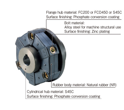
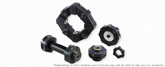
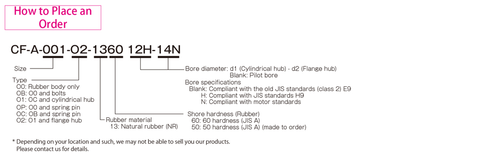
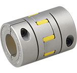
CF-A Models

![]()
CF-A (O0/O1/O2) Types
[O0 Specifications]
| Model | Torque | Misalignment | Max. rotation speed [min-1] | Dynamic torsional stiffness [N・m/rad] | Moment of inertia [kg・m2] | Mass [kg] | ||||
|---|---|---|---|---|---|---|---|---|---|---|
| Nominal [N・m] | Max. [N・m] | Continuous vibration torque [N・m/10Hz] | Parallel [mm] | Angular [°] | Axial [mm] | |||||
| CF-A-001-O0-1360 | 10 | 25 | ±4 | 0.5 | 3 | ±2 | 10000 | 1.47×10² | 2.5×10⁻⁵ | 0.08 |
| CF-A-002-O0-1360 | 20 | 50 | ±8 | 1.0 | 3 | ±3 | 8000 | 2.92×10² | 1.3×10⁻⁴ | 0.2 |
| CF-A-004-O0-1360 | 40 | 100 | ±16 | 1.0 | 3 | ±3 | 7000 | 7.59×10² | 2.8×10⁻⁴ | 0.2 |
| CF-A-008-O0-1360 | 80 | 200 | ±32 | 1.0 | 3 | ±4 | 6500 | 1.44×10³ | 7.6×10⁻⁴ | 0.3 |
| CF-A-012-O0-1360 | 120 | 300 | ±48 | 1.0 | 2 | ±4 | 6500 | 4.38×10³ | 8.3×10⁻⁴ | 0.3 |
| CF-A-016-O0-1360 | 160 | 400 | ±64 | 1.5 | 3 | ±5 | 6000 | 3.28×10³ | 2.5×10⁻³ | 0.7 |
| CF-A-022-O0-1360 | 220 | 550 | ±88 | 1.5 | 2 | ±5 | 6000 | 8.26×10³ | 2.7×10⁻³ | 0.7 |
| CF-A-025-O0-1360 | 250 | 630 | ±100 | 1.5 | 3 | ±5 | 5000 | 4.12×10³ | 4.2×10⁻³ | 0.8 |
| CF-A-028-O0-1360 | 350 | 880 | ±140 | 1.5 | 2 | ±5 | 5000 | 1.05×10⁴ | 4.6×10⁻³ | 1.0 |
| CF-A-030-O0-1360 | 400 | 1000 | ±160 | 1.5 | 3 | ±5 | 4000 | 6.40×10³ | 1.1×10⁻² | 1.5 |
| CF-A-050-O0-1360 | 600 | 1500 | ±240 | 1.5 | 2 | ±5 | 4000 | 1.48×10⁴ | 1.2×10⁻² | 1.7 |
| CF-A-080-O0-1360 | 800 | 2000 | ±320 | 1.5 | 2 | ±4 | 4000 | 2.17×10⁴ | 1.5×10⁻² | 2.3 |
| CF-A-090-O0-1360 | 900 | 2250 | ±360 | 1.5 | 3 | ±5 | 3600 | 1.37×10⁴ | 3.8×10⁻² | 3.2 |
| CF-A-140-O0-1360 | 1400 | 3500 | ±560 | 1.5 | 2 | ±5 | 3600 | 2.90×10⁴ | 4.2×10⁻² | 3.7 |
| CF-A-200-O0-1360 | 2000 | 5000 | ±800 | 1.5 | 2 | ±5 | 3200 | 6.08×10⁴ | 7.8×10⁻² | 5.5 |
| CF-A-250-O0-1360 | 3000 | 8750 | ±1250 | 1.5 | 2 | ±5 | 3000 | 8.28×10⁴ | 0.14 | 7.8 |
| CF-A-400-O0-1360 | 5000 | 12500 | ±2000 | 1.5 | 2 | ±5 | 2800 | 1.25×10⁵ | 0.24 | 11.5 |
*Max. rotation speed does not take into account dynamic balance.
*The dynamic torsional stiffness is about 1.3 times that of the static torsional stiffness.
*Values for moment of inertia and mass are those when the cylindrical hub and flange hub have pilot bores.
[O1 Specifications]
| Model | Torque | Misalignment | Max. rotation speed [min-1] | Dynamic torsional stiffness [N・m/rad] | Moment of inertia [kg・m2] | Mass [kg] | ||||
|---|---|---|---|---|---|---|---|---|---|---|
| Nominal [N・m] | Max. [N・m] | Continuous vibration torque [N・m/10Hz] | Parallel [mm] | Angular [°] | Axial [mm] | |||||
| CF-A-001-O1-1360 | 10 | 25 | ±4 | 0.5 | 3 | ±2 | 10000 | 1.47×10² | 5.8×10⁻⁵ | 0.3 |
| CF-A-002-O1-1360 | 20 | 50 | ±8 | 1.0 | 3 | ±3 | 8000 | 2.92×10² | 2.5×10⁻⁴ | 0.5 |
| CF-A-004-O1-1360 | 40 | 100 | ±16 | 1.0 | 3 | ±3 | 7000 | 7.59×10² | 5.4×10⁻⁴ | 0.6 |
| CF-A-008-O1-1360 | 80 | 200 | ±32 | 1.0 | 3 | ±4 | 6500 | 1.44×10³ | 1.6×10⁻³ | 1.3 |
| CF-A-012-O1-1360 | 120 | 300 | ±48 | 1.0 | 2 | ±4 | 6500 | 4.38×10³ | 1.8×10⁻³ | 1.3 |
| CF-A-016-O1-1360 | 160 | 400 | ±64 | 1.5 | 3 | ±5 | 6000 | 3.28×10³ | 4.3×10⁻³ | 2.3 |
| CF-A-022-O1-1360 | 220 | 550 | ±88 | 1.5 | 2 | ±5 | 6000 | 8.26×10³ | 4.8×10⁻³ | 2.4 |
| CF-A-025-O1-1360 | 250 | 630 | ±100 | 1.5 | 3 | ±5 | 5000 | 4.12×10³ | 8.5×10⁻³ | 3.6 |
| CF-A-028-O1-1360 | 350 | 880 | ±140 | 1.5 | 2 | ±5 | 5000 | 1.05×10⁴ | 9.6×10⁻³ | 3.8 |
| CF-A-030-O1-1360 | 400 | 1000 | ±160 | 1.5 | 3 | ±5 | 4000 | 6.40×10³ | 2.1×10⁻² | 6.0 |
| CF-A-050-O1-1360 | 600 | 1500 | ±240 | 1.5 | 2 | ±5 | 4000 | 1.48×10⁴ | 2.3×10⁻² | 6.3 |
| CF-A-080-O1-1360 | 800 | 2000 | ±320 | 1.5 | 2 | ±4 | 4000 | 2.17×10⁴ | 2.6×10⁻² | 7.6 |
| CF-A-090-O1-1360 | 900 | 2250 | ±360 | 1.5 | 3 | ±5 | 3600 | 1.37×10⁴ | 6.7×10⁻² | 11.8 |
| CF-A-140-O1-1360 | 1400 | 3500 | ±560 | 1.5 | 2 | ±5 | 3600 | 2.90×10⁴ | 7.4×10⁻² | 12.6 |
| CF-A-200-O1-1360 | 2000 | 5000 | ±800 | 1.5 | 2 | ±5 | 3200 | 6.08×10⁴ | 0.14 | 17.8 |
| CF-A-250-O1-1360 | 3000 | 8750 | ±1250 | 1.5 | 2 | ±5 | 3000 | 8.28×10⁴ | 0.24 | 24.5 |
| CF-A-400-O1-1360 | 5000 | 12500 | ±2000 | 1.5 | 2 | ±5 | 2800 | 1.25×10⁵ | 0.44 | 37.6 |
*Max. rotation speed does not take into account dynamic balance.
*The dynamic torsional stiffness is about 1.3 times that of the static torsional stiffness.
*Values for moment of inertia and mass are those when the cylindrical hub and flange hub have pilot bores.
[O2 Specifications]
| Model | Torque | Misalignment | Max. rotation speed [min-1] | Dynamic torsional stiffness [N・m/rad] | Moment of inertia [kg・m2] | Mass [kg] | ||||
|---|---|---|---|---|---|---|---|---|---|---|
| Nominal [N・m] | Max. [N・m] | Continuous vibration torque [N・m/10Hz] | Parallel [mm] | Angular [°] | Axial [mm] | |||||
| CF-A-001-O2-1360 | 10 | 25 | ±4 | 0.5 | 3 | ±2 | 10000 | 1.47×10² | 1.3×10⁻⁴ | 0.5 |
| CF-A-002-O2-1360 | 20 | 50 | ±8 | 1.0 | 3 | ±3 | 8000 | 2.92×10² | 6.3×10⁻⁴ | 1.1 |
| CF-A-004-O2-1360 | 40 | 100 | ±16 | 1.0 | 3 | ±3 | 7000 | 7.59×10² | 1.3×10⁻³ | 1.5 |
| CF-A-008-O2-1360 | 80 | 200 | ±32 | 1.0 | 3 | ±4 | 6500 | 1.44×10³ | 3.7×10⁻³ | 3.0 |
| CF-A-012-O2-1360 | 120 | 300 | ±48 | 1.0 | 2 | ±4 | 6500 | 4.38×10³ | 3.9×10⁻³ | 3.1 |
| CF-A-016-O2-1360 | 160 | 400 | ±64 | 1.5 | 3 | ±5 | 6000 | 3.28×10³ | 1.1×10⁻² | 5.5 |
| CF-A-022-O2-1360 | 220 | 550 | ±88 | 1.5 | 2 | ±5 | 6000 | 8.26×10³ | 1.1×10⁻² | 5.6 |
| CF-A-025-O2-1360 | 250 | 630 | ±100 | 1.5 | 3 | ±5 | 5000 | 4.12×10³ | 2.1×10⁻² | 8.5 |
| CF-A-028-O2-1360 | 350 | 880 | ±140 | 1.5 | 2 | ±5 | 5000 | 1.05×10⁴ | 2.2×10⁻² | 8.7 |
| CF-A-030-O2-1360 | 400 | 1000 | ±160 | 1.5 | 3 | ±5 | 4000 | 6.40×10³ | 4.7×10⁻² | 13.8 |
| CF-A-050-O2-1360 | 600 | 1500 | ±240 | 1.5 | 2 | ±5 | 4000 | 1.48×10⁴ | 5.0×10⁻² | 14.2 |
| CF-A-080-O2-1360 | 800 | 2000 | ±320 | 1.5 | 2 | ±4 | 4000 | 2.17×10⁴ | 5.4×10⁻² | 15.5 |
| CF-A-090-O2-1360 | 900 | 2250 | ±360 | 1.5 | 3 | ±5 | 3600 | 1.37×10⁴ | 0.15 | 26.1 |
| CF-A-140-O2-1360 | 1400 | 3500 | ±560 | 1.5 | 2 | ±5 | 3600 | 2.90×10⁴ | 0.16 | 26.8 |
| CF-A-200-O2-1360 | 2000 | 5000 | ±800 | 1.5 | 2 | ±5 | 3200 | 6.08×10⁴ | 0.30 | 39.4 |
| CF-A-250-O2-1360 | 3000 | 8750 | ±1250 | 1.5 | 2 | ±5 | 3000 | 8.28×10⁴ | 0.50 | 52.3 |
| CF-A-400-O2-1360 | 5000 | 12500 | ±2000 | 1.5 | 2 | ±5 | 2800 | 1.25×10⁵ | 0.97 | 85.0 |
*Max. rotation speed does not take into account dynamic balance.
*The dynamic torsional stiffness is about 1.3 times that of the static torsional stiffness.
*Values for moment of inertia and mass are those when the cylindrical hub and flange hub have pilot bores.
[Dimensions]
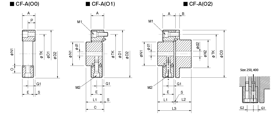
| Model | d1 | d2 | D1 | D2 | D3 | N1 | N2 | L1 | L2 | L3 | A | B | C | E | G1 | G2 | O | P | S | TK | M1 | M2 | ||||
|---|---|---|---|---|---|---|---|---|---|---|---|---|---|---|---|---|---|---|---|---|---|---|---|---|---|---|
| Pilot bore | Min. | Max. | Pilot bore | Min. | Max. | |||||||||||||||||||||
| CF-A-001 | 8 | 9 | 19 | 8 | 9 | 22 | 57 | 56 | 56 | 30 | 36 | 32 | 24 | 58 | 24 | 7 | 34 | 22 | 11 | - | 5 | 18 | 2 | 44 | 2-M6 | 2-M6 |
| CF-A-002 | 10 | 11 | 28 | 9 | 10 | 30 | 86 | 85 | 85 | 40 | 45 | 30 | 28 | 62 | 24 | 8 | 34 | 20 | 10 | - | 14 | 12 | 4 | 68 | 2-M8 | 2-M8 |
| CF-A-004 | 12 | 14 | 30 | 11 | 12 | 36 | 100 | 97 | 100 | 45 | 55 | 34 | 30 | 68 | 28 | 8 | 38 | 24 | 12 | - | 18.3 | 17 | 4 | 80 | 3-M8 | 3-M8 |
| CF-A-008 | 12 | 14 | 38 | 15 | 16 | 46 | 122 | 120 | 120 | 60 | 70 | 40 | 42 | 86 | 32 | 10 | 44 | 28 | 14 | - | 20.5 | 20.5 | 4 | 100 | 3-M10 | 3-M10 |
| CF-A-012 | 12 | 14 | 38 | 15 | 16 | 46 | 122 | 120 | 120 | 60 | 70 | 40 | 42 | 86 | 32 | 10 | 44 | 28 | 14 | - | 20.5 | 20.5 | 4 | 100 | 4-M10 | 4-M10 |
| CF-A-016 | 15 | 16 | 48 | 19 | 20 | 56 | 150 | 150 | 150 | 70 | 85 | 52 | 50 | 108 | 42 | 12 | 58 | 36 | 18 | - | 25 | 23.5 | 6 | 125 | 3-M12 | 3-M12 |
| CF-A-022 | 15 | 16 | 48 | 19 | 20 | 56 | 150 | 150 | 150 | 70 | 85 | 52 | 50 | 108 | 42 | 12 | 58 | 36 | 18 | - | 25 | 23.5 | 6 | 125 | 4-M12 | 4-M12 |
| CF-A-025 | 15 | 16 | 55 | 19 | 20 | 65 | 170 | 170 | 170 | 85 | 100 | 58 | 56 | 120 | 46 | 14 | 64 | 40 | 20 | - | 26 | 26 | 6 | 140 | 3-M14 | 3-M14 |
| CF-A-028 | 15 | 16 | 55 | 19 | 20 | 65 | 170 | 170 | 170 | 85 | 100 | 58 | 56 | 120 | 46 | 14 | 64 | 40 | 20 | - | 26 | 26 | 6 | 140 | 4-M14 | 4-M14 |
| CF-A-030 | 20 | 22 | 65 | 28 | 30 | 80 | 200 | 200 | 200 | 100 | 120 | 68 | 66 | 142 | 58 | 16 | 76 | 50 | 25 | - | 33 | 34.5 | 8 | 165 | 3-M16 | 3-M16 |
| CF-A-050 | 20 | 22 | 65 | 28 | 30 | 80 | 200 | 200 | 200 | 100 | 120 | 68 | 66 | 142 | 58 | 16 | 76 | 50 | 25 | - | 33 | 34.5 | 8 | 165 | 4-M16 | 4-M16 |
| CF-A-080 | 20 | 22 | 65 | 28 | 30 | 80 | 205 | 205 | 200 | 100 | 120 | 80 | 66 | 150 | 65 | 16 | 84 | 61 | 30.5 | - | 33 | 34.5 | 4 | 165 | 4-M16 | 4-M16 |
| CF-A-090 | 30 | 32 | 85 | 30 | 32 | 95 | 260 | 260 | 260 | 125 | 140 | 84 | 80 | 172 | 70 | 19 | 92 | 62 | 31 | - | 46 | 45 | 8 | 215 | 3-M20 | 3-M20 |
| CF-A-140 | 30 | 32 | 85 | 30 | 32 | 95 | 260 | 260 | 260 | 125 | 140 | 84 | 80 | 172 | 70 | 19 | 92 | 62 | 31 | - | 46 | 45 | 8 | 215 | 4-M20 | 4-M20 |
| CF-A-200 | 35 | 38 | 105 | 35 | 38 | 110 | 300 | 300 | 300 | 145 | 160 | 94 | 90 | 192 | 80 | 19 | 102 | 72 | 36 | - | 46 | 45 | 8 | 250 | 4-M20 | 4-M20 |
| CF-A-250 | 40 | 42 | 115 | 40 | 42 | 120 | 340 | 340 | 340 | 160 | 180 | 100 | 100 | 208 | 85 | 19 | 108 | 77 | 22.5 | 32 | 60 | 60 | 8 | 280 | 4-M20 | 8-M20 |
| CF-A-400 | 40 | 42 | 115 | 40 | 42 | 130 | 370 | 370 | 370 | 170 | 200 | 125 | 125 | 260 | 105 | 29 | 135 | 95 | 28.5 | 38 | 70.5 | 67 | 10 | 300 | 4-M24 | 8-M20 |
*Pilot bores are to be drilled into the part. Minimum values for d1 and d2 are given by the minimum bore diameter values in the MIKI PULLEY standard hole-drilling standards and maximum values from the maximum allowable drilled bore diameters.
*The above table values are dimensions when the rubber body is assembled, so the N1, TK, D1, and D2 dimensions prior to rubber body assembly will differ from those above.
*The TK dimension is the bolt mounting pitch diameter of the flange hub or paired mounting part.
*The nominal diameters for bolts M1/M2 are equal to the quantity minus the nominal diameter of the screw threads.
*Using a hex-socket-head bolt with the CF-A-400 requires the special flat washer attached to the rubber body.
[Standard Hole-drilling Standards]

| Models compliant with the old JIS standard (class 2) JIS B 1301 1959 | Models compliant with the new JIS standard (H9) JIS B 1301 1996 | Models compliant with the motor standard JIS C 4210 2001 | ||||||||||||
|---|---|---|---|---|---|---|---|---|---|---|---|---|---|---|
| Nominal bore diameter | Bore diameter (d1, d2) | Keyway width (W1, W2) | Keyway height (T1, T2) | Set screw hole (M) | Nominal bore diameter | Bore diameter (d1, d2) | Keyway width (W1, W2) | Keyway height (T1, T2) | Set screw hole (M) | Nominal bore diameter | Bore diameter (d1, d2) | Keyway width (W1, W2) | Keyway height (T1, T2) | Set screw hole (M) |
| Tolerance H7, H8 | Tolerance E9 | - | Tolerance H7 | Tolerance H9 | - | Tolerance G7, F7 | Tolerance H9 | - | ||||||
| 9 | 9+0.0220 | - | - | 2-M4 | - | - | - | - | - | - | - | - | - | - |
| 10 | 10+0.0220 | - | - | 2-M4 | - | - | - | - | - | - | - | - | - | - |
| 11 | 11+0.0180 | - | - | 2-M4 | - | - | - | - | - | - | - | - | - | - |
| 12 | 12+0.0180 | 4+0.050+0.020 | 13.5+0.30 | 2-M4 | 12H | 12+0.0180 | 4+0.0300 | 13.8+0.30 | 2-M4 | - | - | - | - | - |
| 14 | 14+0.0180 | 5+0.050+0.020 | 16.0+0.30 | 2-M4 | 14H | 14+0.0180 | 5+0.0300 | 16.3+0.30 | 2-M4 | 14N | 14+0.024+0.006 | 5+0.0300 | 16.3+0.30 | 2-M4 |
| 15 | 15+0.0180 | 5+0.050+0.020 | 17.0+0.30 | 2-M4 | 15H | 15+0.0180 | 5+0.0300 | 17.3+0.30 | 2-M4 | - | - | - | - | - |
| 16 | 16+0.0180 | 5+0.050+0.020 | 18.0+0.30 | 2-M4 | 16H | 16+0.0180 | 5+0.0300 | 18.3+0.30 | 2-M4 | - | - | - | - | - |
| 17 | 17+0.0180 | 5+0.050+0.020 | 19.0+0.30 | 2-M4 | 17H | 17+0.0180 | 5+0.0300 | 19.3+0.30 | 2-M4 | - | - | - | - | - |
| 18 | 18+0.0180 | 5+0.050+0.020 | 20.0+0.30 | 2-M4 | 18H | 18+0.0180 | 6+0.0300 | 20.8+0.30 | 2-M5 | - | - | - | - | - |
| 19 | 19+0.0210 | 5+0.050+0.020 | 21.0+0.30 | 2-M4 | 19H | 19+0.0210 | 6+0.0300 | 21.8+0.30 | 2-M5 | 19N | 19+0.028+0.007 | 6+0.0300 | 21.8+0.30 | 2-M5 |
| 20 | 20+0.0210 | 5+0.050+0.020 | 22.0+0.30 | 2-M4 | 20H | 20+0.0210 | 6+0.0300 | 22.8+0.30 | 2-M5 | - | - | - | - | - |
| 22 | 22+0.0210 | 7+0.061+0.025 | 25.0+0.30 | 2-M6 | 22H | 22+0.0210 | 6+0.0300 | 24.8+0.30 | 2-M5 | - | - | - | - | - |
| 24 | 24+0.0210 | 7+0.061+0.025 | 27.0+0.30 | 2-M6 | 24H | 24+0.0210 | 8+0.0360 | 27.3+0.30 | 2-M6 | 24N | 24+0.028+0.007 | 8+0.0360 | 27.3+0.30 | 2-M6 |
| 25 | 25+0.0210 | 7+0.061+0.025 | 28.0+0.30 | 2-M6 | 25H | 25+0.0210 | 8+0.0360 | 28.3+0.30 | 2-M6 | - | - | - | - | - |
| 28 | 28+0.0210 | 7+0.061+0.025 | 31.0+0.30 | 2-M6 | 28H | 28+0.0210 | 8+0.0360 | 31.3+0.30 | 2-M6 | 28N | 28+0.028+0.007 | 8+0.0360 | 31.3+0.30 | 2-M6 |
| 30 | 30+0.0210 | 7+0.061+0.025 | 33.0+0.30 | 2-M6 | 30H | 30+0.0210 | 8+0.0360 | 33.3+0.30 | 2-M6 | - | - | - | - | - |
| 32 | 32+0.0250 | 10+0.061+0.025 | 35.5+0.30 | 2-M8 | 32H | 32+0.0250 | 10+0.0360 | 35.3+0.30 | 2-M8 | - | - | - | - | - |
| 35 | 35+0.0250 | 10+0.061+0.025 | 38.5+0.30 | 2-M8 | 35H | 35+0.0250 | 10+0.0360 | 38.3+0.30 | 2-M8 | - | - | - | - | - |
| 38 | 38+0.0250 | 10+0.061+0.025 | 41.5+0.30 | 2-M8 | 38H | 38+0.0250 | 10+0.0360 | 41.3+0.30 | 2-M8 | 38N | 38+0.050+0.025 | 10+0.0360 | 41.3+0.30 | 2-M8 |
| 40 | 40+0.0250 | 10+0.061+0.025 | 43.5+0.30 | 2-M8 | 40H | 40+0.0250 | 12+0.0430 | 43.3+0.30 | 2-M8 | - | - | - | - | - |
| 42 | 42+0.0250 | 12+0.075+0.032 | 45.5+0.30 | 2-M8 | 42H | 42+0.0250 | 12+0.0430 | 45.3+0.30 | 2-M8 | 42N | 42+0.050+0.025 | 12+0.0430 | 45.3+0.30 | 2-M8 |
| 45 | 45+0.0250 | 12+0.075+0.032 | 48.5+0.30 | 2-M8 | 45H | 45+0.0250 | 14+0.0430 | 48.8+0.30 | 2-M10 | - | - | - | - | - |
| 48 | 48+0.0250 | 12+0.075+0.032 | 51.5+0.30 | 2-M8 | 48H | 48+0.0250 | 14+0.0430 | 51.8+0.30 | 2-M10 | 48N | 48+0.050+0.025 | 14+0.0430 | 51.8+0.30 | 2-M10 |
| 50 | 50+0.0250 | 12+0.075+0.032 | 53.5+0.30 | 2-M8 | 50H | 50+0.0250 | 14+0.0430 | 53.8+0.30 | 2-M10 | - | - | - | - | - |
| 55 | 55+0.0300 | 15+0.075+0.032 | 60.0+0.30 | 2-M10 | 55H | 55+0.0300 | 16+0.0430 | 59.3+0.30 | 2-M10 | 55N | 55+0.060+0.030 | 16+0.0430 | 59.3+0.30 | 2-M10 |
| 56 | 56+0.0300 | 15+0.075+0.032 | 61.0+0.30 | 2-M10 | 56H | 56+0.0300 | 16+0.0430 | 60.3+0.30 | 2-M10 | - | - | - | - | - |
| 60 | 60+0.0300 | 15+0.075+0.032 | 65.0+0.30 | 2-M10 | 60H | 60+0.0300 | 18+0.0430 | 64.4+0.30 | 2-M10 | 60N | 60+0.060+0.030 | 18+0.0430 | 64.4+0.30 | 2-M10 |
| 63 | 63+0.0300 | 18+0.075+0.032 | 69.0+0.30 | 2-M10 | 18H | 63+0.0300 | 18+0.0430 | 67.4+0.30 | 2-M10 | - | - | - | - | - |
| 65 | 65+0.0300 | 18+0.075+0.032 | 71.0+0.30 | 2-M10 | 65H | 65+0.0300 | 18+0.0430 | 69.4+0.30 | 2-M10 | 65N | 65+0.060+0.030 | 18+0.0430 | 69.4+0.30 | 2-M10 |
*All standards starting from ø11 are the same as those in the old JIS standards column.
*Positions of set screws and keyways are not on the same plane.
*Set screws are included with the product.
*Positioning precision for keyway milling is determined by sight.
*Contact Miki Pulley when the keyway requires a positioning precision for a particular flange hub.
*Consult the technical documentation at the end of this volume for standard dimensions for bore drilling other than those given here.
*We can also machine splines. Please contact Miki Pulley.
[Set screw position (Cylinder hub)]
| Cylindrical hub coupling size | Distance from edge[mm] |
|---|---|
| 001 | 6 |
| 002・004 | 6 |
| 008・012 | 7 |
| 016・022・025・028 | 10 |
| 030・050・080 | 11 |
| 090・140 | 13 |
| 200・250・400 | 13 |
[Set screw position (Flange hub)]
| Flange hub coupling size | Distance from edge[mm] |
|---|---|
| 001 | 6 |
| 002・004 | 7 |
| 008・012 | 9 |
| 016・022・025・028 | 10 |
| 030・050・080 | 15 |
| 090・140 | 15 |
| 200・250・400 | 16 |
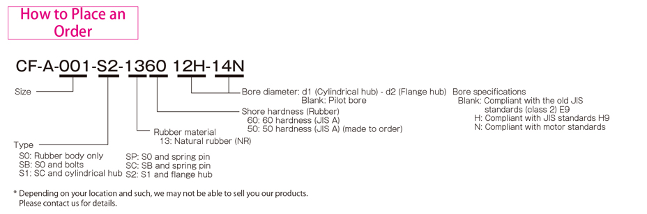
CF-A (S0/S1/S2) Types
[S0 Specifications]
| Model | Torque | Misalignment | Max. rotation speed [min-1] | Dynamic torsional stiffness [N・m/rad] | Moment of inertia [kg・m2] | Mass [kg] | ||||
|---|---|---|---|---|---|---|---|---|---|---|
| Nominal [N・m] | Max. [N・m] | Continuous vibration torque [N・m/10Hz] | Parallel [mm] | Angular [°] | Axial [mm] | |||||
| CF-A-001-S0-1360 | 10 | 25 | ±4 | 0.5 | 3 | ±2 | 10000 | 1.47×10² | 1.9×10⁻⁵ | 0.07 |
| CF-A-002-S0-1360 | 20 | 50 | ±8 | 1.0 | 3 | ±3 | 8000 | 2.92×10² | 1.2×10⁻⁴ | 0.1 |
| CF-A-004-S0-1360 | 40 | 100 | ±16 | 1.0 | 3 | ±3 | 7000 | 7.59×10² | 2.6×10⁻⁴ | 0.2 |
| CF-A-008-S0-1360 | 80 | 200 | ±32 | 1.0 | 3 | ±4 | 6500 | 1.44×10³ | 7.2×10⁻⁴ | 0.3 |
| CF-A-012-S0-1360 | 120 | 300 | ±48 | 1.0 | 2 | ±4 | 6500 | 4.38×10³ | 7.6×10⁻⁴ | 0.3 |
| CF-A-016-S0-1360 | 160 | 400 | ±64 | 1.5 | 3 | ±5 | 6000 | 3.28×10³ | 2.4×10⁻³ | 0.6 |
| CF-A-022-S0-1360 | 220 | 550 | ±88 | 1.5 | 2 | ±5 | 6000 | 8.26×10³ | 2.6×10⁻³ | 0.7 |
| CF-A-025-S0-1360 | 250 | 630 | ±100 | 1.5 | 3 | ±5 | 5000 | 4.12×10³ | 4.0×10⁻³ | 0.8 |
| CF-A-028-S0-1360 | 350 | 880 | ±140 | 1.5 | 2 | ±5 | 5000 | 1.05×10⁴ | 4.3×10⁻³ | 0.9 |
| CF-A-030-S0-1360 | 400 | 1000 | ±160 | 1.5 | 3 | ±5 | 4000 | 6.40×10³ | 1.0×10⁻² | 1.4 |
| CF-A-050-S0-1360 | 600 | 1500 | ±240 | 1.5 | 2 | ±5 | 4000 | 1.48×10⁴ | 1.1×10⁻² | 1.7 |
| CF-A-080-S0-1360 | 800 | 2000 | ±320 | 1.5 | 2 | ±4 | 4000 | 2.17×10⁴ | 1.5×10⁻² | 2.3 |
| CF-A-090-S0-1360 | 900 | 2250 | ±360 | 1.5 | 3 | ±5 | 3600 | 1.37×10⁴ | 3.6×10⁻² | 3.1 |
| CF-A-140-S0-1360 | 1400 | 3500 | ±560 | 1.5 | 2 | ±5 | 3600 | 2.90×10⁴ | 3.8×10⁻² | 3.4 |
| CF-A-200-S0-1360 | 2000 | 5000 | ±800 | 1.5 | 2 | ±5 | 3200 | 6.08×10⁴ | 7.5×10⁻² | 5.3 |
| CF-A-250-S0-1360 | 3000 | 8750 | ±1250 | 1.5 | 2 | ±5 | 3000 | 8.28×10⁴ | 0.14 | 7.0 |
| CF-A-400-S0-1360 | 5000 | 12500 | ±2000 | 1.5 | 2 | ±5 | 2800 | 1.25×10⁵ | 0.22 | 10.7 |
*Max. rotation speed does not take into account dynamic balance.
*The dynamic torsional stiffness is about 1.3 times that of the static torsional stiffness.
*Values for moment of inertia and mass are those when the cylindrical hub and flange hub have pilot bores.
[S1 Specifications]
| Model | Torque | Misalignment | Max. rotation speed [min-1] | Dynamic torsional stiffness [N・m/rad] | Moment of inertia [kg・m2] | Mass [kg] | ||||
|---|---|---|---|---|---|---|---|---|---|---|
| Nominal [N・m] | Max. [N・m] | Continuous vibration torque [N・m/10Hz] | Parallel [mm] | Angular [°] | Axial [mm] | |||||
| CF-A-001-S1-1360 | 10 | 25 | ±4 | 0.5 | 3 | ±2 | 10000 | 1.47×10² | 6.0×10⁻⁵ | 0.3 |
| CF-A-002-S1-1360 | 20 | 50 | ±8 | 1.0 | 3 | ±3 | 8000 | 2.92×10² | 2.8×10⁻⁴ | 0.5 |
| CF-A-004-S1-1360 | 40 | 100 | ±16 | 1.0 | 3 | ±3 | 7000 | 7.59×10² | 5.8×10⁻⁴ | 0.7 |
| CF-A-008-S1-1360 | 80 | 200 | ±32 | 1.0 | 3 | ±4 | 6500 | 1.44×10³ | 1.8×10⁻³ | 1.4 |
| CF-A-012-S1-1360 | 120 | 300 | ±48 | 1.0 | 2 | ±4 | 6500 | 4.38×10³ | 2.0×10⁻³ | 1.4 |
| CF-A-016-S1-1360 | 160 | 400 | ±64 | 1.5 | 3 | ±5 | 6000 | 3.28×10³ | 4.7×10⁻³ | 2.5 |
| CF-A-022-S1-1360 | 220 | 550 | ±88 | 1.5 | 2 | ±5 | 6000 | 8.26×10³ | 5.4×10⁻³ | 2.6 |
| CF-A-025-S1-1360 | 250 | 630 | ±100 | 1.5 | 3 | ±5 | 5000 | 4.12×10³ | 9.2×10⁻³ | 3.8 |
| CF-A-028-S1-1360 | 350 | 880 | ±140 | 1.5 | 2 | ±5 | 5000 | 1.05×10⁴ | 1.1×10⁻³ | 4.0 |
| CF-A-030-S1-1360 | 400 | 1000 | ±160 | 1.5 | 3 | ±5 | 4000 | 6.40×10³ | 2.2×10⁻² | 6.3 |
| CF-A-050-S1-1360 | 600 | 1500 | ±240 | 1.5 | 2 | ±5 | 4000 | 1.48×10⁴ | 2.5×10⁻² | 6.8 |
| CF-A-080-S1-1360 | 800 | 2000 | ±320 | 1.5 | 2 | ±4 | 4000 | 2.17×10⁴ | 2.9×10⁻² | 8.1 |
| CF-A-090-S1-1360 | 900 | 2250 | ±360 | 1.5 | 3 | ±5 | 3600 | 1.37×10⁴ | 7.1×10⁻² | 12.4 |
| CF-A-140-S1-1360 | 1400 | 3500 | ±560 | 1.5 | 2 | ±5 | 3600 | 2.90×10⁴ | 7.9×10⁻² | 13.3 |
| CF-A-200-S1-1360 | 2000 | 5000 | ±800 | 1.5 | 2 | ±5 | 3200 | 6.08×10⁴ | 0.15 | 18.5 |
| CF-A-250-S1-1360 | 3000 | 8750 | ±1250 | 1.5 | 2 | ±5 | 3000 | 8.28×10⁴ | 0.25 | 24.5 |
| CF-A-400-S1-1360 | 5000 | 12500 | ±2000 | 1.5 | 2 | ±5 | 2800 | 1.25×10⁵ | 0.49 | 39.5 |
*Max. rotation speed does not take into account dynamic balance.
*The dynamic torsional stiffness is about 1.3 times that of the static torsional stiffness.
*Values for moment of inertia and mass are those when the cylindrical hub and flange hub have pilot bores.
[S2 Specifications]
| Model | Torque | Misalignment | Max. rotation speed [min-1] | Dynamic torsional stiffness [N・m/rad] | Moment of inertia [kg・m2] | Mass [kg] | ||||
|---|---|---|---|---|---|---|---|---|---|---|
| Nominal [N・m] | Max. [N・m] | Continuous vibration torque [N・m/10Hz] | Parallel [mm] | Angular [°] | Axial [mm] | |||||
| CF-A-001-S2-1360 | 10 | 25 | ±4 | 0.5 | 3 | ±2 | 10000 | 1.47×10² | 1.4×10⁻⁴ | 0.5 |
| CF-A-002-S2-1360 | 20 | 50 | ±8 | 1.0 | 3 | ±3 | 8000 | 2.92×10² | 6.6×10⁻⁴ | 1.1 |
| CF-A-004-S2-1360 | 40 | 100 | ±16 | 1.0 | 3 | ±3 | 7000 | 7.59×10² | 1.4×10⁻³ | 1.5 |
| CF-A-008-S2-1360 | 80 | 200 | ±32 | 1.0 | 3 | ±4 | 6500 | 1.44×10³ | 3.9×10⁻³ | 3.1 |
| CF-A-012-S2-1360 | 120 | 300 | ±48 | 1.0 | 2 | ±4 | 6500 | 4.38×10³ | 4.1×10⁻³ | 3.2 |
| CF-A-016-S2-1360 | 160 | 400 | ±64 | 1.5 | 3 | ±5 | 6000 | 3.28×10³ | 1.1×10⁻² | 5.6 |
| CF-A-022-S2-1360 | 220 | 550 | ±88 | 1.5 | 2 | ±5 | 6000 | 8.26×10³ | 1.2×10⁻² | 5.8 |
| CF-A-025-S2-1360 | 250 | 630 | ±100 | 1.5 | 3 | ±5 | 5000 | 4.12×10³ | 2.2×10⁻² | 8.7 |
| CF-A-028-S2-1360 | 350 | 880 | ±140 | 1.5 | 2 | ±5 | 5000 | 1.05×10⁴ | 2.3×10⁻² | 8.9 |
| CF-A-030-S2-1360 | 400 | 1000 | ±160 | 1.5 | 3 | ±5 | 4000 | 6.40×10³ | 4.9×10⁻² | 14.2 |
| CF-A-050-S2-1360 | 600 | 1500 | ±240 | 1.5 | 2 | ±5 | 4000 | 1.48×10⁴ | 5.2×10⁻² | 14.6 |
| CF-A-080-S2-1360 | 800 | 2000 | ±320 | 1.5 | 2 | ±4 | 4000 | 2.17×10⁴ | 5.6×10⁻² | 16.0 |
| CF-A-090-S2-1360 | 900 | 2250 | ±360 | 1.5 | 3 | ±5 | 3600 | 1.37×10⁴ | 0.16 | 26.6 |
| CF-A-140-S2-1360 | 1400 | 3500 | ±560 | 1.5 | 2 | ±5 | 3600 | 2.90×10⁴ | 0.17 | 27.5 |
| CF-A-200-S2-1360 | 2000 | 5000 | ±800 | 1.5 | 2 | ±5 | 3200 | 6.08×10⁴ | 0.32 | 40.1 |
| CF-A-250-S2-1360 | 3000 | 8750 | ±1250 | 1.5 | 2 | ±5 | 3000 | 8.28×10⁴ | 0.50 | 52.3 |
| CF-A-400-S2-1360 | 5000 | 12500 | ±2000 | 1.5 | 2 | ±5 | 2800 | 1.25×10⁵ | 1.00 | 86.9 |
*Max. rotation speed does not take into account dynamic balance.
*The dynamic torsional stiffness is about 1.3 times that of the static torsional stiffness.
*Values for moment of inertia and mass are those when the cylindrical hub and flange hub have pilot bores.
[Dimensions]
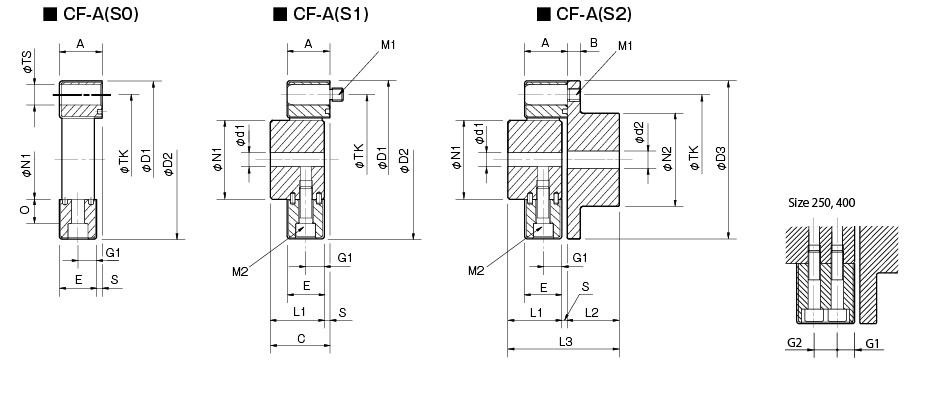
| Model | d1 | d2 | D1 | D2 | D3 | N1 | N2 | L1 | L2 | L3 | A | B | C | E | G1 | G2 | O | S | TS | TK | M1 | M2 | ||||
|---|---|---|---|---|---|---|---|---|---|---|---|---|---|---|---|---|---|---|---|---|---|---|---|---|---|---|
| Pilot bore | Min. | Max. | Pilot bore | Min. | Max. | |||||||||||||||||||||
| CF-A-001 | 8 | 9 | 19 | 8 | 9 | 22 | 57 | 56 | 56 | 30 | 36 | 32 | 24 | 58 | 24 | 7 | 34 | 22 | 11 | - | 5 | 2 | 10 | 44 | 2-M6 | 2-M6 |
| CF-A-002 | 10 | 11 | 28 | 9 | 10 | 30 | 86 | 85 | 85 | 40 | 45 | 30 | 28 | 62 | 24 | 8 | 34 | 20 | 10 | - | 14 | 4 | 14 | 68 | 2-M8 | 2-M8 |
| CF-A-004 | 12 | 14 | 30 | 11 | 12 | 36 | 100 | 97 | 100 | 45 | 55 | 34 | 30 | 68 | 28 | 8 | 38 | 24 | 12 | - | 18.3 | 4 | 14 | 80 | 3-M8 | 3-M8 |
| CF-A-008 | 12 | 14 | 38 | 15 | 16 | 46 | 122 | 120 | 120 | 60 | 70 | 40 | 42 | 86 | 32 | 10 | 44 | 28 | 14 | - | 20.5 | 4 | 17 | 100 | 3-M10 | 3-M10 |
| CF-A-012 | 12 | 14 | 38 | 15 | 16 | 46 | 122 | 120 | 120 | 60 | 70 | 40 | 42 | 86 | 32 | 10 | 44 | 28 | 14 | - | 20.5 | 4 | 17 | 100 | 4-M10 | 4-M10 |
| CF-A-016 | 15 | 16 | 48 | 19 | 20 | 56 | 150 | 150 | 150 | 70 | 85 | 52 | 50 | 108 | 42 | 12 | 58 | 36 | 18 | - | 25 | 6 | 19 | 125 | 3-M12 | 3-M12 |
| CF-A-022 | 15 | 16 | 48 | 19 | 20 | 56 | 150 | 150 | 150 | 70 | 85 | 52 | 50 | 108 | 42 | 12 | 58 | 36 | 18 | - | 25 | 6 | 19 | 125 | 4-M12 | 4-M12 |
| CF-A-025 | 15 | 16 | 55 | 19 | 20 | 65 | 170 | 170 | 170 | 85 | 100 | 58 | 56 | 120 | 46 | 14 | 64 | 40 | 20 | - | 26 | 6 | 22 | 140 | 3-M14 | 3-M14 |
| CF-A-028 | 15 | 16 | 55 | 19 | 20 | 65 | 170 | 170 | 170 | 85 | 100 | 58 | 56 | 120 | 46 | 14 | 64 | 40 | 20 | - | 26 | 6 | 22 | 140 | 4-M14 | 4-M14 |
| CF-A-030 | 20 | 22 | 65 | 28 | 30 | 80 | 200 | 200 | 200 | 100 | 120 | 68 | 66 | 142 | 58 | 16 | 76 | 50 | 25 | - | 33 | 8 | 25 | 165 | 3-M16 | 3-M16 |
| CF-A-050 | 20 | 22 | 65 | 28 | 30 | 80 | 200 | 200 | 200 | 100 | 120 | 68 | 66 | 142 | 58 | 16 | 76 | 50 | 25 | - | 33 | 8 | 25 | 165 | 4-M16 | 4-M16 |
| CF-A-080 | 20 | 22 | 65 | 28 | 30 | 80 | 205 | 205 | 200 | 100 | 120 | 80 | 66 | 150 | 65 | 16 | 84 | 61 | 30.5 | - | 33 | 4 | 25 | 165 | 4-M16 | 4-M16 |
| CF-A-090 | 30 | 32 | 85 | 30 | 32 | 95 | 260 | 260 | 260 | 125 | 140 | 84 | 80 | 172 | 70 | 19 | 92 | 62 | 31 | - | 46 | 8 | 32 | 215 | 3-M20 | 3-M20 |
| CF-A-140 | 30 | 32 | 85 | 30 | 32 | 95 | 260 | 260 | 260 | 125 | 140 | 84 | 80 | 172 | 70 | 19 | 92 | 62 | 31 | - | 46 | 8 | 32 | 215 | 4-M20 | 4-M20 |
| CF-A-200 | 35 | 38 | 105 | 35 | 38 | 110 | 300 | 300 | 300 | 145 | 160 | 94 | 90 | 192 | 80 | 19 | 102 | 72 | 36 | - | 46 | 8 | 32 | 250 | 4-M20 | 4-M20 |
| CF-A-250 | 40 | 42 | 115 | 40 | 42 | 120 | 340 | 340 | 340 | 160 | 180 | 100 | 100 | 208 | 85 | 19 | 108 | 77 | 22.5 | 32 | 60 | 8 | 32 | 280 | 4-M20 | 8-M20 |
| CF-A-400 | 40 | 42 | 115 | 40 | 42 | 130 | 370 | 370 | 370 | 170 | 200 | 125 | 125 | 260 | 105 | 29 | 135 | 95 | 28.5 | 38 | 70.5 | 10 | 45 | 300 | 4-M24 | 8-M20 |
*Pilot bores are to be drilled into the part. Minimum values for d1 and d2 are given by the minimum bore diameter values in the MIKI PULLEY standard hole-drilling standards and maximum values from the maximum allowable drilled bore diameters.
*The above table values are dimensions when the rubber body is assembled, so the N1, TK, D1, and D2 dimensions prior to rubber body assembly will differ from those above.
*The TK dimension is the bolt mounting pitch diameter of the flange hub or paired mounting part, but it is possible to change to make the mounting easier. Please contact MIKI PULLEY for the details.
*The TS dimension is the H8 plug gauge reference dimension. However, size 001 has a tolerance of +0.10, while sizes 002 and 004 have tolerances of +0.150.
*The nominal diameters for bolts M1/M2 are equal to the quantity minus the nominal diameter of the screw threads.
*Using a hex-socket-head bolt with the CF-A-400 requires the special flat washer attached to the rubber body.
[Standard Hole-drilling Standards]
| Models compliant with the old JIS standard (class 2) JIS B 1301 1959 | Models compliant with the new JIS standard (H9) JIS B 1301 1996 | Models compliant with the motor standard JIS C 4210 2001 | ||||||||||||
|---|---|---|---|---|---|---|---|---|---|---|---|---|---|---|
| Nominal bore diameter | Bore diameter (d1, d2) | Keyway width (W1, W2) | Keyway height (T1, T2) | Set screw hole (M) | Nominal bore diameter | Bore diameter (d1, d2) | Keyway width (W1, W2) | Keyway height (T1, T2) | Set screw hole (M) | Nominal bore diameter | Bore diameter (d1, d2) | Keyway width (W1, W2) | Keyway height (T1, T2) | Set screw hole (M) |
| Tolerance H7, H8 | Tolerance E9 | - | Tolerance H7 | Tolerance H9 | - | Tolerance G7, F7 | Tolerance H9 | - | ||||||
| 9 | 9+0.0220 | - | - | 2-M4 | - | - | - | - | - | - | - | - | - | - |
| 10 | 10+0.0220 | - | - | 2-M4 | - | - | - | - | - | - | - | - | - | - |
| 11 | 11+0.0180 | - | - | 2-M4 | - | - | - | - | - | - | - | - | - | - |
| 12 | 12+0.0180 | 4+0.050+0.020 | 13.5+0.30 | 2-M4 | 12H | 12+0.0180 | 4+0.0300 | 13.8+0.30 | 2-M4 | - | - | - | - | - |
| 14 | 14+0.0180 | 5+0.050+0.020 | 16.0+0.30 | 2-M4 | 14H | 14+0.0180 | 5+0.0300 | 16.3+0.30 | 2-M4 | 14N | 14+0.024+0.006 | 5+0.0300 | 16.3+0.30 | 2-M4 |
| 15 | 15+0.0180 | 5+0.050+0.020 | 17.0+0.30 | 2-M4 | 15H | 15+0.0180 | 5+0.0300 | 17.3+0.30 | 2-M4 | - | - | - | - | - |
| 16 | 16+0.0180 | 5+0.050+0.020 | 18.0+0.30 | 2-M4 | 16H | 16+0.0180 | 5+0.0300 | 18.3+0.30 | 2-M4 | - | - | - | - | - |
| 17 | 17+0.0180 | 5+0.050+0.020 | 19.0+0.30 | 2-M4 | 17H | 17+0.0180 | 5+0.0300 | 19.3+0.30 | 2-M4 | - | - | - | - | - |
| 18 | 18+0.0180 | 5+0.050+0.020 | 20.0+0.30 | 2-M4 | 18H | 18+0.0180 | 6+0.0300 | 20.8+0.30 | 2-M5 | - | - | - | - | - |
| 19 | 19+0.0210 | 5+0.050+0.020 | 21.0+0.30 | 2-M4 | 19H | 19+0.0210 | 6+0.0300 | 21.8+0.30 | 2-M5 | 19N | 19+0.028+0.007 | 6+0.0300 | 21.8+0.30 | 2-M5 |
| 20 | 20+0.0210 | 5+0.050+0.020 | 22.0+0.30 | 2-M4 | 20H | 20+0.0210 | 6+0.0300 | 22.8+0.30 | 2-M5 | - | - | - | - | - |
| 22 | 22+0.0210 | 7+0.061+0.025 | 25.0+0.30 | 2-M6 | 22H | 22+0.0210 | 6+0.0300 | 24.8+0.30 | 2-M5 | - | - | - | - | - |
| 24 | 24+0.0210 | 7+0.061+0.025 | 27.0+0.30 | 2-M6 | 24H | 24+0.0210 | 8+0.0360 | 27.3+0.30 | 2-M6 | 24N | 24+0.028+0.007 | 8+0.0360 | 27.3+0.30 | 2-M6 |
| 25 | 25+0.0210 | 7+0.061+0.025 | 28.0+0.30 | 2-M6 | 25H | 25+0.0210 | 8+0.0360 | 28.3+0.30 | 2-M6 | - | - | - | - | - |
| 28 | 28+0.0210 | 7+0.061+0.025 | 31.0+0.30 | 2-M6 | 28H | 28+0.0210 | 8+0.0360 | 31.3+0.30 | 2-M6 | 28N | 28+0.028+0.007 | 8+0.0360 | 31.3+0.30 | 2-M6 |
| 30 | 30+0.0210 | 7+0.061+0.025 | 33.0+0.30 | 2-M6 | 30H | 30+0.0210 | 8+0.0360 | 33.3+0.30 | 2-M6 | - | - | - | - | - |
| 32 | 32+0.0250 | 10+0.061+0.025 | 35.5+0.30 | 2-M8 | 32H | 32+0.0250 | 10+0.0360 | 35.3+0.30 | 2-M8 | - | - | - | - | - |
| 35 | 35+0.0250 | 10+0.061+0.025 | 38.5+0.30 | 2-M8 | 35H | 35+0.0250 | 10+0.0360 | 38.3+0.30 | 2-M8 | - | - | - | - | - |
| 38 | 38+0.0250 | 10+0.061+0.025 | 41.5+0.30 | 2-M8 | 38H | 38+0.0250 | 10+0.0360 | 41.3+0.30 | 2-M8 | 38N | 38+0.050+0.025 | 10+0.0360 | 41.3+0.30 | 2-M8 |
| 40 | 40+0.0250 | 10+0.061+0.025 | 43.5+0.30 | 2-M8 | 40H | 40+0.0250 | 12+0.0430 | 43.3+0.30 | 2-M8 | - | - | - | - | - |
| 42 | 42+0.0250 | 12+0.075+0.032 | 45.5+0.30 | 2-M8 | 42H | 42+0.0250 | 12+0.0430 | 45.3+0.30 | 2-M8 | 42N | 42+0.050+0.025 | 12+0.0430 | 45.3+0.30 | 2-M8 |
| 45 | 45+0.0250 | 12+0.075+0.032 | 48.5+0.30 | 2-M8 | 45H | 45+0.0250 | 14+0.0430 | 48.8+0.30 | 2-M10 | - | - | - | - | - |
| 48 | 48+0.0250 | 12+0.075+0.032 | 51.5+0.30 | 2-M8 | 48H | 48+0.0250 | 14+0.0430 | 51.8+0.30 | 2-M10 | 48N | 48+0.050+0.025 | 14+0.0430 | 51.8+0.30 | 2-M10 |
| 50 | 50+0.0250 | 12+0.075+0.032 | 53.5+0.30 | 2-M8 | 50H | 50+0.0250 | 14+0.0430 | 53.8+0.30 | 2-M10 | - | - | - | - | - |
| 55 | 55+0.0300 | 15+0.075+0.032 | 60.0+0.30 | 2-M10 | 55H | 55+0.0300 | 16+0.0430 | 59.3+0.30 | 2-M10 | 55N | 55+0.060+0.030 | 16+0.0430 | 59.3+0.30 | 2-M10 |
| 56 | 56+0.0300 | 15+0.075+0.032 | 61.0+0.30 | 2-M10 | 56H | 56+0.0300 | 16+0.0430 | 60.3+0.30 | 2-M10 | - | - | - | - | - |
| 60 | 60+0.0300 | 15+0.075+0.032 | 65.0+0.30 | 2-M10 | 60H | 60+0.0300 | 18+0.0430 | 64.4+0.30 | 2-M10 | 60N | 60+0.060+0.030 | 18+0.0430 | 64.4+0.30 | 2-M10 |
| 63 | 63+0.0300 | 18+0.075+0.032 | 69.0+0.30 | 2-M10 | 18H | 63+0.0300 | 18+0.0430 | 67.4+0.30 | 2-M10 | - | - | - | - | - |
| 65 | 65+0.0300 | 18+0.075+0.032 | 71.0+0.30 | 2-M10 | 65H | 65+0.0300 | 18+0.0430 | 69.4+0.30 | 2-M10 | 65N | 65+0.060+0.030 | 18+0.0430 | 69.4+0.30 | 2-M10 |
*All standards starting from ø11 are the same as those in the old JIS standards column.
*Positions of set screws and keyways are not on the same plane.
*Set screws are included with the product.
*Positioning precision for keyway milling is determined by sight.
*Contact Miki Pulley when the keyway requires a positioning precision for a particular flange hub.
*Consult the technical documentation at the end of this volume for standard dimensions for bore drilling other than those given here.
*We can also machine splines. Please contact Miki Pulley.
[Set screw position (Cylinder hub)]
| Cylindrical hub coupling size | Distance from edge[mm] |
|---|---|
| 001 | 6 |
| 002・004 | 6 |
| 008・012 | 7 |
| 016・022・025・028 | 10 |
| 030・050・080 | 11 |
| 090・140 | 13 |
| 200・250・400 | 13 |
[Set screw position (Flange hub)]
| Flange hub coupling size | Distance from edge[mm] |
|---|---|
| 001 | 6 |
| 002・004 | 7 |
| 008・012 | 9 |
| 016・022・025・028 | 10 |
| 030・050・080 | 15 |
| 090・140 | 15 |
| 200・250・400 | 16 |
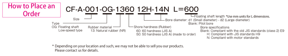
CF-A (OG) Types
[Specifications]
| Model | Torque | Misalignment | Max. rotation speed [min-1] | Dynamic torsional stiffness [N・m/rad] | Moment of inertia [kg・m2] | Mass [kg] | ||||
|---|---|---|---|---|---|---|---|---|---|---|
| Nominal [N・m] | Max. [N・m] | Continuous vibration torque [N・m/10Hz] | Parallel [mm] | Angular [°] | Axial [mm] | |||||
| CF-A-001-OG-1360 | 10 | 25 | ±4 | 24.8 | 3 | ±2 | 1000 | 7.35×101 | 3.5×10⁻⁴ | 1.4 |
| CF-A-002-OG-1360 | 20 | 50 | ±8 | 24.7 | 3 | ±3 | 1000 | 1.46×10² | 1.5×10⁻³ | 2.5 |
| CF-A-004-OG-1360 | 40 | 100 | ±16 | 24.5 | 3 | ±3 | 1000 | 3.80×10² | 2.9×10⁻³ | 3.3 |
| CF-A-008-OG-1360 | 80 | 200 | ±32 | 24.3 | 3 | ±4 | 1000 | 7.20×10² | 8.0×10⁻³ | 6.2 |
| CF-A-012-OG-1360 | 120 | 300 | ±48 | 16.2 | 2 | ±4 | 1000 | 2.19×10³ | 8.4×10⁻³ | 6.4 |
| CF-A-016-OG-1360 | 160 | 400 | ±64 | 23.7 | 3 | ±5 | 1000 | 1.64×10³ | 2.1×10⁻² | 10.6 |
| CF-A-022-OG-1360 | 220 | 550 | ±88 | 15.8 | 2 | ±5 | 1000 | 4.13×10³ | 2.3×10⁻² | 11.0 |
| CF-A-025-OG-1360 | 250 | 630 | ±100 | 23.5 | 3 | ±5 | 1000 | 2.06×10³ | 4.2×10⁻² | 15.9 |
| CF-A-028-OG-1360 | 350 | 880 | ±140 | 15.6 | 2 | ±5 | 1000 | 0.53×10⁴ | 4.4×10⁻² | 16.5 |
| CF-A-030-OG-1360 | 400 | 1000 | ±160 | 22.7 | 3 | ±5 | 1000 | 3.20×10³ | 9.6×10⁻² | 25.8 |
| CF-A-050-OG-1360 | 600 | 1500 | ±240 | 15.2 | 2 | ±5 | 1000 | 7.40×10³ | 0.10 | 26.6 |
| CF-A-080-OG-1360 | 800 | 2000 | ±320 | 15.1 | 2 | ±4 | 1000 | 1.09×10⁴ | 0.11 | 28.7 |
| CF-A-090-OG-1360 | 900 | 2250 | ±360 | 22.1 | 3 | ±5 | 1000 | 6.85×10³ | 0.30 | 47.8 |
| CF-A-140-OG-1360 | 1400 | 3500 | ±560 | 14.7 | 2 | ±5 | 1000 | 1.45×10⁴ | 0.31 | 49.3 |
| CF-A-200-OG-1360 | 2000 | 5000 | ±800 | 14.4 | 2 | ±5 | 1000 | 3.04×10⁴ | 0.55 | 74.3 |
| CF-A-250-OG-1360 | 3000 | 8750 | ±1250 | 14.2 | 2 | ±5 | 1000 | 4.14×10⁴ | 0.99 | 97.7 |
| CF-A-400-OG-1360 | 5000 | 12500 | ±2000 | 13.4 | 2 | ±5 | 1000 | 6.25×10⁴ | 1.77 | 164.6 |
*The values of the above table are for a flange hub with pilot bore when L = 500.
*Max. rotation speed does not take into account dynamic balance.
*The dynamic torsional stiffness is about 1.3 times that of the static torsional stiffness.
[Dimensions]
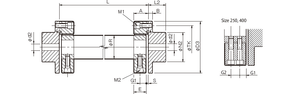
| Model | d2 | D3 | N2 | L2 | A | B | R | E | G1 | G2 | S | TK | M1 | M2 | ||
|---|---|---|---|---|---|---|---|---|---|---|---|---|---|---|---|---|
| Pilot bore | Min. | Max. | ||||||||||||||
| CF-A-001-OG-1360 | 8 | 9 | 22 | 56 | 36 | 24 | 24 | 7 | 30 | 22 | 11 | - | 2 | 44 | 2-M6 | 2-M6 |
| CF-A-002-OG-1360 | 9 | 10 | 30 | 85 | 45 | 28 | 24 | 8 | 40 | 20 | 10 | - | 4 | 68 | 2-M8 | 2-M8 |
| CF-A-004-OG-1360 | 11 | 12 | 36 | 100 | 55 | 30 | 28 | 8 | 45 | 24 | 12 | - | 4 | 80 | 3-M8 | 3-M8 |
| CF-A-008-OG-1360 | 15 | 16 | 46 | 120 | 70 | 42 | 32 | 10 | 60 | 28 | 14 | - | 4 | 100 | 3-M10 | 3-M10 |
| CF-A-012-OG-1360 | 15 | 16 | 46 | 120 | 70 | 42 | 32 | 10 | 60 | 28 | 14 | - | 4 | 100 | 4-M10 | 4-M10 |
| CF-A-016-OG-1360 | 19 | 20 | 56 | 150 | 85 | 50 | 42 | 12 | 70 | 36 | 18 | - | 6 | 125 | 3-M12 | 3-M12 |
| CF-A-022-OG-1360 | 19 | 20 | 56 | 150 | 85 | 50 | 42 | 12 | 70 | 36 | 18 | - | 6 | 125 | 4-M12 | 4-M12 |
| CF-A-025-OG-1360 | 19 | 20 | 65 | 170 | 100 | 56 | 46 | 14 | 85 | 40 | 20 | - | 6 | 140 | 3-M14 | 3-M14 |
| CF-A-028-OG-1360 | 19 | 20 | 65 | 170 | 100 | 56 | 46 | 14 | 85 | 40 | 20 | - | 6 | 140 | 4-M14 | 4-M14 |
| CF-A-030-OG-1360 | 28 | 30 | 80 | 200 | 120 | 66 | 58 | 16 | 100 | 50 | 25 | - | 8 | 165 | 3-M16 | 3-M16 |
| CF-A-050-OG-1360 | 28 | 30 | 80 | 200 | 120 | 66 | 58 | 16 | 100 | 50 | 25 | - | 8 | 165 | 4-M16 | 4-M16 |
| CF-A-080-OG-1360 | 28 | 30 | 80 | 200 | 120 | 66 | 65 | 16 | 100 | 61 | 30.5 | - | 4 | 165 | 4-M16 | 4-M16 |
| CF-A-090-OG-1360 | 30 | 32 | 95 | 260 | 140 | 80 | 70 | 19 | 125 | 62 | 31 | - | 8 | 215 | 3-M20 | 3-M20 |
| CF-A-140-OG-1360 | 30 | 32 | 95 | 260 | 140 | 80 | 70 | 19 | 125 | 62 | 31 | - | 8 | 215 | 4-M20 | 4-M20 |
| CF-A-200-OG-1360 | 35 | 38 | 110 | 300 | 160 | 90 | 80 | 19 | 145 | 72 | 36 | - | 8 | 250 | 4-M20 | 4-M20 |
| CF-A-250-OG-1360 | 40 | 42 | 120 | 340 | 180 | 100 | 85 | 19 | 160 | 77 | 22.5 | 32 | 8 | 280 | 4-M20 | 8-M20 |
| CF-A-400-OG-1360 | 40 | 42 | 130 | 370 | 200 | 125 | 105 | 29 | 170 | 95 | 28.5 | 38 | 10 | 300 | 4-M24 | 8-M20 |
*Pilot bores are to be drilled into the part. Minimum values for d2 are given by the minimum bore diameter values in the MIKI PULLEY standard hole-drilling standards and maximum values from the maximumallowable drilled bore diameters.
*The nominal diameters for bolts M1/M2 are equal to the quantity minus the nominal diameter of the screw threads, where the quantity is for one side.
*The L dimension has a standard length of 1000 mm or less. Dimension L must at least allow enough space for an M1 bolt to be mounted.
[Standard Hole-drilling Standards]
| Models compliant with the old JIS standard (class 2) JIS B 1301 1959 | Models compliant with the new JIS standard (H9) JIS B 1301 1996 | Models compliant with the motor standard JIS C 4210 2001 | ||||||||||||
|---|---|---|---|---|---|---|---|---|---|---|---|---|---|---|
| Nominal bore diameter | Bore diameter (d1, d2) | Keyway width (W1, W2) | Keyway height (T1, T2) | Set screw hole (M) | Nominal bore diameter | Bore diameter (d1, d2) | Keyway width (W1, W2) | Keyway height (T1, T2) | Set screw hole (M) | Nominal bore diameter | Bore diameter (d1, d2) | Keyway width (W1, W2) | Keyway height (T1, T2) | Set screw hole (M) |
| Tolerance H7, H8 | Tolerance E9 | - | Tolerance H7 | Tolerance H9 | - | Tolerance G7, F7 | Tolerance H9 | - | ||||||
| 9 | 9+0.0220 | - | - | 2-M4 | - | - | - | - | - | - | - | - | - | - |
| 10 | 10+0.0220 | - | - | 2-M4 | - | - | - | - | - | - | - | - | - | - |
| 11 | 11+0.0180 | - | - | 2-M4 | - | - | - | - | - | - | - | - | - | - |
| 12 | 12+0.0180 | 4+0.050+0.020 | 13.5+0.30 | 2-M4 | 12H | 12+0.0180 | 4+0.0300 | 13.8+0.30 | 2-M4 | - | - | - | - | - |
| 14 | 14+0.0180 | 5+0.050+0.020 | 16.0+0.30 | 2-M4 | 14H | 14+0.0180 | 5+0.0300 | 16.3+0.30 | 2-M4 | 14N | 14+0.024+0.006 | 5+0.0300 | 16.3+0.30 | 2-M4 |
| 15 | 15+0.0180 | 5+0.050+0.020 | 17.0+0.30 | 2-M4 | 15H | 15+0.0180 | 5+0.0300 | 17.3+0.30 | 2-M4 | - | - | - | - | - |
| 16 | 16+0.0180 | 5+0.050+0.020 | 18.0+0.30 | 2-M4 | 16H | 16+0.0180 | 5+0.0300 | 18.3+0.30 | 2-M4 | - | - | - | - | - |
| 17 | 17+0.0180 | 5+0.050+0.020 | 19.0+0.30 | 2-M4 | 17H | 17+0.0180 | 5+0.0300 | 19.3+0.30 | 2-M4 | - | - | - | - | - |
| 18 | 18+0.0180 | 5+0.050+0.020 | 20.0+0.30 | 2-M4 | 18H | 18+0.0180 | 6+0.0300 | 20.8+0.30 | 2-M5 | - | - | - | - | - |
| 19 | 19+0.0210 | 5+0.050+0.020 | 21.0+0.30 | 2-M4 | 19H | 19+0.0210 | 6+0.0300 | 21.8+0.30 | 2-M5 | 19N | 19+0.028+0.007 | 6+0.0300 | 21.8+0.30 | 2-M5 |
| 20 | 20+0.0210 | 5+0.050+0.020 | 22.0+0.30 | 2-M4 | 20H | 20+0.0210 | 6+0.0300 | 22.8+0.30 | 2-M5 | - | - | - | - | - |
| 22 | 22+0.0210 | 7+0.061+0.025 | 25.0+0.30 | 2-M6 | 22H | 22+0.0210 | 6+0.0300 | 24.8+0.30 | 2-M5 | - | - | - | - | - |
| 24 | 24+0.0210 | 7+0.061+0.025 | 27.0+0.30 | 2-M6 | 24H | 24+0.0210 | 8+0.0360 | 27.3+0.30 | 2-M6 | 24N | 24+0.028+0.007 | 8+0.0360 | 27.3+0.30 | 2-M6 |
| 25 | 25+0.0210 | 7+0.061+0.025 | 28.0+0.30 | 2-M6 | 25H | 25+0.0210 | 8+0.0360 | 28.3+0.30 | 2-M6 | - | - | - | - | - |
| 28 | 28+0.0210 | 7+0.061+0.025 | 31.0+0.30 | 2-M6 | 28H | 28+0.0210 | 8+0.0360 | 31.3+0.30 | 2-M6 | 28N | 28+0.028+0.007 | 8+0.0360 | 31.3+0.30 | 2-M6 |
| 30 | 30+0.0210 | 7+0.061+0.025 | 33.0+0.30 | 2-M6 | 30H | 30+0.0210 | 8+0.0360 | 33.3+0.30 | 2-M6 | - | - | - | - | - |
| 32 | 32+0.0250 | 10+0.061+0.025 | 35.5+0.30 | 2-M8 | 32H | 32+0.0250 | 10+0.0360 | 35.3+0.30 | 2-M8 | - | - | - | - | - |
| 35 | 35+0.0250 | 10+0.061+0.025 | 38.5+0.30 | 2-M8 | 35H | 35+0.0250 | 10+0.0360 | 38.3+0.30 | 2-M8 | - | - | - | - | - |
| 38 | 38+0.0250 | 10+0.061+0.025 | 41.5+0.30 | 2-M8 | 38H | 38+0.0250 | 10+0.0360 | 41.3+0.30 | 2-M8 | 38N | 38+0.050+0.025 | 10+0.0360 | 41.3+0.30 | 2-M8 |
| 40 | 40+0.0250 | 10+0.061+0.025 | 43.5+0.30 | 2-M8 | 40H | 40+0.0250 | 12+0.0430 | 43.3+0.30 | 2-M8 | - | - | - | - | - |
| 42 | 42+0.0250 | 12+0.075+0.032 | 45.5+0.30 | 2-M8 | 42H | 42+0.0250 | 12+0.0430 | 45.3+0.30 | 2-M8 | 42N | 42+0.050+0.025 | 12+0.0430 | 45.3+0.30 | 2-M8 |
| 45 | 45+0.0250 | 12+0.075+0.032 | 48.5+0.30 | 2-M8 | 45H | 45+0.0250 | 14+0.0430 | 48.8+0.30 | 2-M10 | - | - | - | - | - |
| 48 | 48+0.0250 | 12+0.075+0.032 | 51.5+0.30 | 2-M8 | 48H | 48+0.0250 | 14+0.0430 | 51.8+0.30 | 2-M10 | 48N | 48+0.050+0.025 | 14+0.0430 | 51.8+0.30 | 2-M10 |
| 50 | 50+0.0250 | 12+0.075+0.032 | 53.5+0.30 | 2-M8 | 50H | 50+0.0250 | 14+0.0430 | 53.8+0.30 | 2-M10 | - | - | - | - | - |
| 55 | 55+0.0300 | 15+0.075+0.032 | 60.0+0.30 | 2-M10 | 55H | 55+0.0300 | 16+0.0430 | 59.3+0.30 | 2-M10 | 55N | 55+0.060+0.030 | 16+0.0430 | 59.3+0.30 | 2-M10 |
| 56 | 56+0.0300 | 15+0.075+0.032 | 61.0+0.30 | 2-M10 | 56H | 56+0.0300 | 16+0.0430 | 60.3+0.30 | 2-M10 | - | - | - | - | - |
| 60 | 60+0.0300 | 15+0.075+0.032 | 65.0+0.30 | 2-M10 | 60H | 60+0.0300 | 18+0.0430 | 64.4+0.30 | 2-M10 | 60N | 60+0.060+0.030 | 18+0.0430 | 64.4+0.30 | 2-M10 |
| 63 | 63+0.0300 | 18+0.075+0.032 | 69.0+0.30 | 2-M10 | 18H | 63+0.0300 | 18+0.0430 | 67.4+0.30 | 2-M10 | - | - | - | - | - |
| 65 | 65+0.0300 | 18+0.075+0.032 | 71.0+0.30 | 2-M10 | 65H | 65+0.0300 | 18+0.0430 | 69.4+0.30 | 2-M10 | 65N | 65+0.060+0.030 | 18+0.0430 | 69.4+0.30 | 2-M10 |
*All standards starting from ø11 are the same as those in the old JIS standards column.
*Positions of set screws and keyways are not on the same plane.
*Set screws are included with the product.
*Positioning precision for keyway milling is determined by sight.
*Contact Miki Pulley when the keyway requires a positioning precision for a particular flange hub.
*Consult the technical documentation at the end of this volume for standard dimensions for bore drilling other than those given here.
*We can also machine splines. Please contact Miki Pulley.
[Set screw position (Cylinder hub)]
| Cylindrical hub coupling size | Distance from edge[mm] |
|---|---|
| 001 | 6 |
| 002・004 | 6 |
| 008・012 | 7 |
| 016・022・025・028 | 10 |
| 030・050・080 | 11 |
| 090・140 | 13 |
| 200・250・400 | 13 |
[Set screw position (Flange hub)]
| Flange hub coupling size | Distance from edge[mm] |
|---|---|
| 001 | 6 |
| 002・004 | 7 |
| 008・012 | 9 |
| 016・022・025・028 | 10 |
| 030・050・080 | 15 |
| 090・140 | 15 |
| 200・250・400 | 16 |
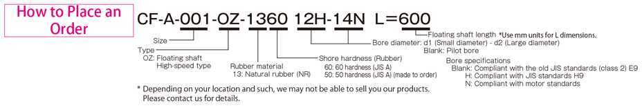
CF-A (OZ) Types
[Specifications]
| Model | Torque | Misalignment | Max. rotation speed [min-1] | Dynamic torsional stiffness [N・m/rad] | Moment of inertia [kg・m2] | Mass [kg] | ||||
|---|---|---|---|---|---|---|---|---|---|---|
| Nominal [N・m] | Max. [N・m] | Continuous vibration torque [N・m/10Hz] | Parallel [mm] | Angular [°] | Axial [mm] | |||||
| CF-A-001-OZ-1360 | 10 | 25 | ±4 | 8.1 | 1 | ±2 | 10000 | 7.35×101 | 4.3×10⁻⁴ | 1.6 |
| CF-A-002-OZ-1360 | 20 | 50 | ±8 | 8.1 | 1 | ±3 | 8000 | 1.46×10² | 2.0×10⁻³ | 3.1 |
| CF-A-004-OZ-1360 | 40 | 100 | ±16 | 8.0 | 1 | ±3 | 7000 | 3.80×10² | 3.6×10⁻³ | 4.0 |
| CF-A-008-OZ-1360 | 80 | 200 | ±32 | 7.8 | 1 | ±4 | 6500 | 7.20×10² | 1.1×10⁻² | 7.7 |
| CF-A-012-OZ-1360 | 120 | 300 | ±48 | 7.8 | 1 | ±4 | 6500 | 2.19×10³ | 1.1×10⁻² | 7.8 |
| CF-A-016-OZ-1360 | 160 | 400 | ±64 | 7.5 | 1 | ±5 | 6000 | 1.64×10³ | 2.9×10⁻² | 13.1 |
| CF-A-022-OZ-1360 | 220 | 550 | ±88 | 7.5 | 1 | ±5 | 6000 | 4.13×10³ | 3.0×10⁻² | 13.4 |
| CF-A-025-OZ-1360 | 250 | 630 | ±100 | 7.5 | 1 | ±5 | 5000 | 2.06×10³ | 5.4×10⁻² | 19.1 |
| CF-A-028-OZ-1360 | 350 | 880 | ±140 | 7.5 | 1 | ±5 | 5000 | 0.53×10⁴ | 5.7×10⁻² | 19.6 |
| CF-A-030-OZ-1360 | 400 | 1000 | ±160 | 7.2 | 1 | ±5 | 4000 | 3.20×10³ | 0.12 | 30.2 |
| CF-A-050-OZ-1360 | 600 | 1500 | ±240 | 7.2 | 1 | ±5 | 4000 | 7.40×10³ | 0.12 | 30.9 |
| CF-A-080-OZ-1360 | 800 | 2000 | ±320 | 7.2 | 1 | ±4 | 4000 | 1.09×10⁴ | 0.13 | 33.0 |
| CF-A-090-OZ-1360 | 900 | 2250 | ±360 | 7.0 | 1 | ±5 | 3600 | 6.85×10³ | 0.37 | 55.3 |
| CF-A-140-OZ-1360 | 1400 | 3500 | ±560 | 7.0 | 1 | ±5 | 3600 | 1.45×10⁴ | 0.38 | 56.7 |
| CF-A-200-OZ-1360 | 2000 | 5000 | ±800 | 6.7 | 1 | ±5 | 3200 | 3.04×10⁴ | 0.74 | 91.3 |
| CF-A-250-OZ-1360 | 3000 | 8750 | ±1250 | 6.6 | 1 | ±5 | 3000 | 4.14×10⁴ | 1.19 | 111.9 |
| CF-A-400-OZ-1360 | 5000 | 12500 | ±2000 | 6.2 | 1 | ±5 | 2800 | 6.25×10⁴ | 2.47 | 190.0 |
*The values of the above table are for a flange hub with pilot bore when L = 500.
*Max. rotation speed does not take into account dynamic balance.
*The dynamic torsional stiffness is about 1.3 times that of the static torsional stiffness.
[Dimensions]
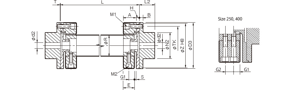
| Model | d2 | D3 | N2 | L2 | A | B | H | R | E | T | G1 | G2 | S | TK | Z | M1 | M2 | ||
|---|---|---|---|---|---|---|---|---|---|---|---|---|---|---|---|---|---|---|---|
| Pilot bore | Min. | Max. | |||||||||||||||||
| CF-A-001-OZ-1360 | 8 | 9 | 22 | 56 | 36 | 24 | 24 | 7 | 5 | 30 | 22 | 1.5 | 11 | - | 2 | 44 | 52 | 2-M6 | 2-M6 |
| CF-A-002-OZ-1360 | 9 | 10 | 30 | 85 | 45 | 28 | 24 | 8 | 5 | 40 | 20 | 1.5 | 10 | - | 4 | 68 | 80 | 2-M8 | 2-M8 |
| CF-A-004-OZ-1360 | 11 | 12 | 36 | 100 | 55 | 30 | 28 | 8 | 5 | 45 | 24 | 1.5 | 12 | - | 4 | 80 | 95 | 3-M8 | 3-M8 |
| CF-A-008-OZ-1360 | 15 | 16 | 46 | 120 | 70 | 42 | 32 | 10 | 10 | 60 | 28 | 1.5 | 14 | - | 4 | 100 | 115 | 3-M10 | 3-M10 |
| CF-A-012-OZ-1360 | 15 | 16 | 46 | 120 | 70 | 42 | 32 | 10 | 10 | 60 | 28 | 1.5 | 14 | - | 4 | 100 | 115 | 4-M10 | 4-M10 |
| CF-A-016-OZ-1360 | 19 | 20 | 56 | 150 | 85 | 50 | 42 | 12 | 10 | 70 | 36 | 1.5 | 18 | - | 6 | 125 | 145 | 3-M12 | 3-M12 |
| CF-A-022-OZ-1360 | 19 | 20 | 56 | 150 | 85 | 50 | 42 | 12 | 10 | 70 | 36 | 1.5 | 18 | - | 6 | 125 | 145 | 4-M12 | 4-M12 |
| CF-A-025-OZ-1360 | 19 | 20 | 65 | 170 | 100 | 56 | 46 | 14 | 10 | 85 | 40 | 1.5 | 20 | - | 6 | 140 | 165 | 3-M14 | 3-M14 |
| CF-A-028-OZ-1360 | 19 | 20 | 65 | 170 | 100 | 56 | 46 | 14 | 10 | 85 | 40 | 1.5 | 20 | - | 6 | 140 | 165 | 4-M14 | 4-M14 |
| CF-A-030-OZ-1360 | 28 | 30 | 80 | 200 | 120 | 66 | 58 | 16 | 10 | 100 | 50 | 1.5 | 25 | - | 8 | 165 | 195 | 3-M16 | 3-M16 |
| CF-A-050-OZ-1360 | 28 | 30 | 80 | 200 | 120 | 66 | 58 | 16 | 10 | 100 | 50 | 1.5 | 25 | - | 8 | 165 | 195 | 4-M16 | 4-M16 |
| CF-A-080-OZ-1360 | 28 | 30 | 80 | 200 | 120 | 66 | 65 | 16 | 10 | 100 | 61 | 1.5 | 30.5 | - | 4 | 165 | 195 | 4-M16 | 4-M16 |
| CF-A-090-OZ-1360 | 30 | 32 | 95 | 260 | 140 | 80 | 70 | 19 | 10 | 125 | 62 | 2 | 31 | - | 8 | 215 | 250 | 3-M20 | 3-M20 |
| CF-A-140-OZ-1360 | 30 | 32 | 95 | 260 | 140 | 80 | 70 | 19 | 10 | 125 | 62 | 2 | 31 | - | 8 | 215 | 250 | 4-M20 | 4-M20 |
| CF-A-200-OZ-1360 | 35 | 38 | 110 | 300 | 160 | 90 | 80 | 19 | 15 | 145 | 72 | 2 | 36 | - | 8 | 250 | 290 | 4-M20 | 4-M20 |
| CF-A-250-OZ-1360 | 40 | 42 | 120 | 340 | 180 | 100 | 85 | 19 | 15 | 160 | 77 | 2.5 | 22.5 | 32 | 8 | 280 | 330 | 4-M20 | 8-M20 |
| CF-A-400-OZ-1360 | 40 | 42 | 130 | 370 | 200 | 125 | 105 | 29 | 15 | 170 | 95 | 2 | 28.5 | 38 | 10 | 300 | 360 | 4-M24 | 8-M20 |
*Pilot bores are to be drilled into the part. Minimum values for d2 are given by the minimum bore diameter values in the MIKI PULLEY standard hole-drilling standards and maximum values from the maximum allowable drilled bore diameters.
*The nominal diameters for bolts M1/M2 are equal to the quantity minus the nominal diameter of the screw threads, where the quantity is for one side.
*See the floating length graph for the L dimension. Dimension L must at least allow enough space for an M1 bolt to be mounted.
[Standard Hole-drilling Standards]
| Models compliant with the old JIS standard (class 2) JIS B 1301 1959 | Models compliant with the new JIS standard (H9) JIS B 1301 1996 | Models compliant with the motor standard JIS C 4210 2001 | ||||||||||||
|---|---|---|---|---|---|---|---|---|---|---|---|---|---|---|
| Nominal bore diameter | Bore diameter (d1, d2) | Keyway width (W1, W2) | Keyway height (T1, T2) | Set screw hole (M) | Nominal bore diameter | Bore diameter (d1, d2) | Keyway width (W1, W2) | Keyway height (T1, T2) | Set screw hole (M) | Nominal bore diameter | Bore diameter (d1, d2) | Keyway width (W1, W2) | Keyway height (T1, T2) | Set screw hole (M) |
| Tolerance H7, H8 | Tolerance E9 | - | Tolerance H7 | Tolerance H9 | - | Tolerance G7, F7 | Tolerance H9 | - | ||||||
| 9 | 9+0.0220 | - | - | 2-M4 | - | - | - | - | - | - | - | - | - | - |
| 10 | 10+0.0220 | - | - | 2-M4 | - | - | - | - | - | - | - | - | - | - |
| 11 | 11+0.0180 | - | - | 2-M4 | - | - | - | - | - | - | - | - | - | - |
| 12 | 12+0.0180 | 4+0.050+0.020 | 13.5+0.30 | 2-M4 | 12H | 12+0.0180 | 4+0.0300 | 13.8+0.30 | 2-M4 | - | - | - | - | - |
| 14 | 14+0.0180 | 5+0.050+0.020 | 16.0+0.30 | 2-M4 | 14H | 14+0.0180 | 5+0.0300 | 16.3+0.30 | 2-M4 | 14N | 14+0.024+0.006 | 5+0.0300 | 16.3+0.30 | 2-M4 |
| 15 | 15+0.0180 | 5+0.050+0.020 | 17.0+0.30 | 2-M4 | 15H | 15+0.0180 | 5+0.0300 | 17.3+0.30 | 2-M4 | - | - | - | - | - |
| 16 | 16+0.0180 | 5+0.050+0.020 | 18.0+0.30 | 2-M4 | 16H | 16+0.0180 | 5+0.0300 | 18.3+0.30 | 2-M4 | - | - | - | - | - |
| 17 | 17+0.0180 | 5+0.050+0.020 | 19.0+0.30 | 2-M4 | 17H | 17+0.0180 | 5+0.0300 | 19.3+0.30 | 2-M4 | - | - | - | - | - |
| 18 | 18+0.0180 | 5+0.050+0.020 | 20.0+0.30 | 2-M4 | 18H | 18+0.0180 | 6+0.0300 | 20.8+0.30 | 2-M5 | - | - | - | - | - |
| 19 | 19+0.0210 | 5+0.050+0.020 | 21.0+0.30 | 2-M4 | 19H | 19+0.0210 | 6+0.0300 | 21.8+0.30 | 2-M5 | 19N | 19+0.028+0.007 | 6+0.0300 | 21.8+0.30 | 2-M5 |
| 20 | 20+0.0210 | 5+0.050+0.020 | 22.0+0.30 | 2-M4 | 20H | 20+0.0210 | 6+0.0300 | 22.8+0.30 | 2-M5 | - | - | - | - | - |
| 22 | 22+0.0210 | 7+0.061+0.025 | 25.0+0.30 | 2-M6 | 22H | 22+0.0210 | 6+0.0300 | 24.8+0.30 | 2-M5 | - | - | - | - | - |
| 24 | 24+0.0210 | 7+0.061+0.025 | 27.0+0.30 | 2-M6 | 24H | 24+0.0210 | 8+0.0360 | 27.3+0.30 | 2-M6 | 24N | 24+0.028+0.007 | 8+0.0360 | 27.3+0.30 | 2-M6 |
| 25 | 25+0.0210 | 7+0.061+0.025 | 28.0+0.30 | 2-M6 | 25H | 25+0.0210 | 8+0.0360 | 28.3+0.30 | 2-M6 | - | - | - | - | - |
| 28 | 28+0.0210 | 7+0.061+0.025 | 31.0+0.30 | 2-M6 | 28H | 28+0.0210 | 8+0.0360 | 31.3+0.30 | 2-M6 | 28N | 28+0.028+0.007 | 8+0.0360 | 31.3+0.30 | 2-M6 |
| 30 | 30+0.0210 | 7+0.061+0.025 | 33.0+0.30 | 2-M6 | 30H | 30+0.0210 | 8+0.0360 | 33.3+0.30 | 2-M6 | - | - | - | - | - |
| 32 | 32+0.0250 | 10+0.061+0.025 | 35.5+0.30 | 2-M8 | 32H | 32+0.0250 | 10+0.0360 | 35.3+0.30 | 2-M8 | - | - | - | - | - |
| 35 | 35+0.0250 | 10+0.061+0.025 | 38.5+0.30 | 2-M8 | 35H | 35+0.0250 | 10+0.0360 | 38.3+0.30 | 2-M8 | - | - | - | - | - |
| 38 | 38+0.0250 | 10+0.061+0.025 | 41.5+0.30 | 2-M8 | 38H | 38+0.0250 | 10+0.0360 | 41.3+0.30 | 2-M8 | 38N | 38+0.050+0.025 | 10+0.0360 | 41.3+0.30 | 2-M8 |
| 40 | 40+0.0250 | 10+0.061+0.025 | 43.5+0.30 | 2-M8 | 40H | 40+0.0250 | 12+0.0430 | 43.3+0.30 | 2-M8 | - | - | - | - | - |
| 42 | 42+0.0250 | 12+0.075+0.032 | 45.5+0.30 | 2-M8 | 42H | 42+0.0250 | 12+0.0430 | 45.3+0.30 | 2-M8 | 42N | 42+0.050+0.025 | 12+0.0430 | 45.3+0.30 | 2-M8 |
| 45 | 45+0.0250 | 12+0.075+0.032 | 48.5+0.30 | 2-M8 | 45H | 45+0.0250 | 14+0.0430 | 48.8+0.30 | 2-M10 | - | - | - | - | - |
| 48 | 48+0.0250 | 12+0.075+0.032 | 51.5+0.30 | 2-M8 | 48H | 48+0.0250 | 14+0.0430 | 51.8+0.30 | 2-M10 | 48N | 48+0.050+0.025 | 14+0.0430 | 51.8+0.30 | 2-M10 |
| 50 | 50+0.0250 | 12+0.075+0.032 | 53.5+0.30 | 2-M8 | 50H | 50+0.0250 | 14+0.0430 | 53.8+0.30 | 2-M10 | - | - | - | - | - |
| 55 | 55+0.0300 | 15+0.075+0.032 | 60.0+0.30 | 2-M10 | 55H | 55+0.0300 | 16+0.0430 | 59.3+0.30 | 2-M10 | 55N | 55+0.060+0.030 | 16+0.0430 | 59.3+0.30 | 2-M10 |
| 56 | 56+0.0300 | 15+0.075+0.032 | 61.0+0.30 | 2-M10 | 56H | 56+0.0300 | 16+0.0430 | 60.3+0.30 | 2-M10 | - | - | - | - | - |
| 60 | 60+0.0300 | 15+0.075+0.032 | 65.0+0.30 | 2-M10 | 60H | 60+0.0300 | 18+0.0430 | 64.4+0.30 | 2-M10 | 60N | 60+0.060+0.030 | 18+0.0430 | 64.4+0.30 | 2-M10 |
| 63 | 63+0.0300 | 18+0.075+0.032 | 69.0+0.30 | 2-M10 | 18H | 63+0.0300 | 18+0.0430 | 67.4+0.30 | 2-M10 | - | - | - | - | - |
| 65 | 65+0.0300 | 18+0.075+0.032 | 71.0+0.30 | 2-M10 | 65H | 65+0.0300 | 18+0.0430 | 69.4+0.30 | 2-M10 | 65N | 65+0.060+0.030 | 18+0.0430 | 69.4+0.30 | 2-M10 |
*All standards starting from ø11 are the same as those in the old JIS standards column.
*Positions of set screws and keyways are not on the same plane.
*Set screws are included with the product.
*Positioning precision for keyway milling is determined by sight.
*Contact Miki Pulley when the keyway requires a positioning precision for a particular flange hub.
*Consult the technical documentation at the end of this volume for standard dimensions for bore drilling other than those given here.
*We can also machine splines. Please contact Miki Pulley.
[Set screw position (Cylinder hub)]
| Cylindrical hub coupling size | Distance from edge[mm] |
|---|---|
| 001 | 6 |
| 002・004 | 6 |
| 008・012 | 7 |
| 016・022・025・028 | 10 |
| 030・050・080 | 11 |
| 090・140 | 13 |
| 200・250・400 | 13 |
[Set screw position (Flange hub)]
| Flange hub coupling size | Distance from edge[mm] |
|---|---|
| 001 | 6 |
| 002・004 | 7 |
| 008・012 | 9 |
| 016・022・025・028 | 10 |
| 030・050・080 | 15 |
| 090・140 | 15 |
| 200・250・400 | 16 |

![]()
![]()
![]()
![]()
![]()
![]()