日本語
日本語 English
 Deutsch
 中文
中文 한국어
한국어


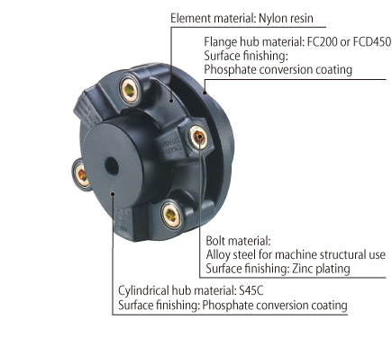
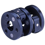
CF-X Models

![]()
CF-X (O0/O1/O2) Types
[Specifications]
| Model | Torque | Misalignment | Max. rotation speed [min-1] | Static torsional stiffness [N・m/rad] | |||
|---|---|---|---|---|---|---|---|
| Nominal [N・m] | Max. [N・m] | Parallel [mm] | Angular [°] | Axial [mm] | |||
| CF-X-001 | 15 | 30 | 0.1 | 1 | ±0.5 | 10000 | 3.0×10³ |
| CF-X-002 | 30 | 60 | 0.1 | 1 | ±0.5 | 10000 | 6.0×10³ |
| CF-X-004 | 60 | 120 | 0.1 | 1 | ±0.5 | 8000 | 2.3×10⁴ |
| CF-X-008 | 120 | 250 | 0.1 | 1 | ±0.5 | 7000 | 5.8×10⁴ |
| CF-X-016 | 240 | 500 | 0.1 | 1 | ±0.5 | 6000 | 1.1×10⁵ |
| CF-X-025 | 370 | 800 | 0.1 | 1 | ±0.5 | 5000 | 1.7×10⁵ |
| Model | Moment of inertia [kg・m2] | Mass [kg] |
|---|---|---|
| CF-X-001-O0 | 2.03×10⁻⁵ | 0.04 |
| CF-X-002-O0 | 9.75×10⁻⁵ | 0.1 |
| CF-X-004-O0 | 2.30×10⁻⁴ | 0.2 |
| CF-X-008-O0 | 6.63×10⁻⁴ | 0.3 |
| CF-X-016-O0 | 1.56×10⁻³ | 0.5 |
| CF-X-025-O0 | 2.77×10⁻³ | 0.6 |
| Model | Moment of inertia [kg・m2] | Mass [kg] |
|---|---|---|
| CF-X-001-O1 | 5.25×10⁻⁵ | 0.2 |
| CF-X-002-O1 | 2.20×10⁻⁴ | 0.4 |
| CF-X-004-O1 | 4.83×10⁻⁴ | 0.6 |
| CF-X-008-O1 | 1.49×10⁻³ | 1.3 |
| CF-X-016-O1 | 3.49×10⁻³ | 2.2 |
| CF-X-025-O1 | 7.07×10⁻³ | 3.5 |
| Model | Moment of inertia [kg・m2] | Mass [kg] |
|---|---|---|
| CF-X-001-O2 | 1.22×10⁻⁴ | 0.5 |
| CF-X-002-O2 | 5.74×10⁻⁴ | 0.9 |
| CF-X-004-O2 | 1.19×10⁻³ | 1.4 |
| CF-X-008-O2 | 3.49×10⁻³ | 2.9 |
| CF-X-016-O2 | 9.20×10⁻³ | 5 |
| CF-X-025-O2 | 1.83×10⁻² | 7.9 |
*Max. rotation speed does not take into account dynamic balance.
*Static torsional stiff ness values given are from measurements taken at 20℃ .
*Values for moment of inertia and mass are those when the cylindrical hub and flange hub have pilot bores.
[Dimensions]
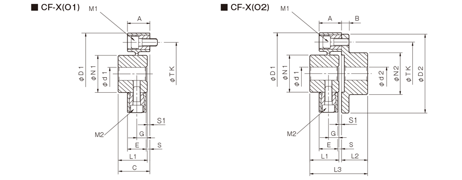
| Model | d1 | d2 | D1 | D2 | N1 | N2 | L1 | L2 | L3 | A | B | C | E | G | S | S1 | M1 | M2 | TK | ||||
|---|---|---|---|---|---|---|---|---|---|---|---|---|---|---|---|---|---|---|---|---|---|---|---|
| Pilot bore | Min. | Max. | Pilot bore | Min. | Max. | ||||||||||||||||||
| CF-X-001 | 8 | 9 | 19 | 8 | 9 | 22 | 57 | 56 | 30 | 36 | 32 | 24 | 57 | 24 | 7 | 33 | 18 | 11 | 3 | 1 | 2-M6 | 2-M6 | 44 |
| CF-X-002 | 10 | 11 | 26 | 9 | 10 | 30 | 88 | 85 | 40 | 45 | 30 | 28 | 62 | 24 | 8 | 34 | 20 | 10 | 4 | 4 | 2-M8 | 2-M8 | 68 |
| CF-X-004 | 12 | 14 | 30 | 11 | 12 | 36 | 100 | 100 | 45 | 55 | 34 | 30 | 66.5 | 25 | 8 | 36.5 | 21 | 12 | 4 | 2.5 | 3-M8 | 3-M8 | 80 |
| CF-X-008 | 12 | 14 | 38 | 15 | 16 | 46 | 125 | 120 | 60 | 70 | 40 | 42 | 85 | 30 | 10 | 43 | 26 | 14 | 4 | 3 | 3-M10 | 3-M10 | 100 |
| CF-X-016 | 15 | 16 | 48 | 19 | 20 | 56 | 155 | 150 | 70 | 85 | 52 | 50 | 105 | 35 | 12 | 55 | 28 | 18 | 7 | 3 | 3-M12 | 3-M12 | 125 |
| CF-X-025 | 15 | 16 | 55 | 19 | 20 | 65 | 175 | 170 | 85 | 100 | 58 | 56 | 117 | 40 | 14 | 61 | 34 | 20 | 6 | 3 | 3-M14 | 3-M14 | 140 |
*Pilot bores are to be drilled into the part. Minimum values for d1 and d2 are given by the minimum bore diameter values in the MIKI PULLEY standard hole-drilling standards and maximum values from the maximum allowable drilled bore diameters.
*The nominal diameters for bolts M1/M2 are equal to the quantity minus the nominal diameter of the screw threads.
*The TK dimension is the bolt mounting pitch diameter of the flange hub or paired mounting part.

[Standard bore diameter]
| Model | Standard bore diameter [mm] | |||||||||||||||||
|---|---|---|---|---|---|---|---|---|---|---|---|---|---|---|---|---|---|---|
| 10 | 11 | 12 | 14 | 15 | 16 | 18 | 19 | 20 | 22 | 24 | 25 | 28 | 32 | 30 | 35 | 38 | ||
| CF-X-001-O2-C | d1 | ● | ● | ● | ● | ● | ● | |||||||||||
| d2 | ● | ● | ● | ● | ● | ● | ● | ● | ||||||||||
| CF-X-002-O2-C | d1 | ● | ● | ● | ● | ● | ● | ● | ● | ● | ● | |||||||
| d2 | ● | ● | ● | ● | ● | ● | ● | ● | ● | ● | ||||||||
| CF-X-004-O2-C | d1 | ● | ● | ● | ● | ● | ● | ● | ● | ● | ● | |||||||
| d2 | ● | ● | ● | ● | ● | ● | ● | ● | ● | ● | ● | ● | ● | ● | ||||
[Standard Hole-drilling Standards]
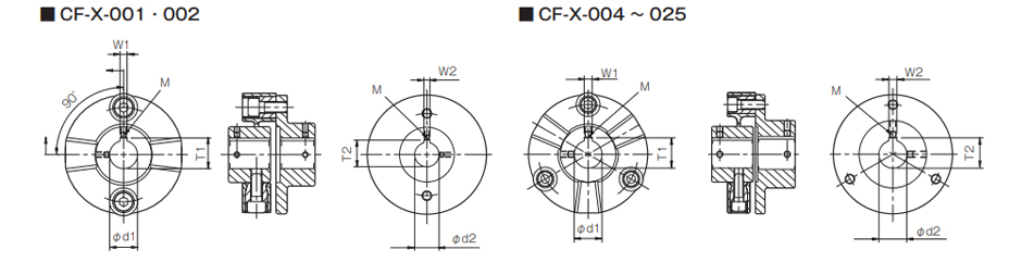
| Models compliant with the old JIS standard (class 2) JIS B 1301 1959 | Models compliant with the new JIS standard (H9) JIS B 1301 1996 | Models compliant with the motor standard JIS C 4210 2001 | ||||||||||||
|---|---|---|---|---|---|---|---|---|---|---|---|---|---|---|
| Nominal bore diameter | Bore diameter (d1, d2) | Keyway width (W1, W2) | Keyway height (T1, T2) | Set screw hole (M) | Nominal bore diameter | Bore diameter (d1, d2) | Keyway width (W1, W2) | Keyway height (T1, T2) | Set screw hole (M) | Nominal bore diameter | Bore diameter (d1, d2) | Keyway width (W1, W2) | Keyway height (T1, T2) | Set screw hole (M) |
| Tolerance H7, H8 | Tolerance E9 | - | Tolerance H7 | Tolerance H9 | - | Tolerance G7, F7 | Tolerance H9 | - | ||||||
| 9 | 9+0.0220 | - | - | 2-M4 | - | - | - | - | - | - | - | - | - | - |
| 10 | 10+0.0220 | - | - | 2-M4 | - | - | - | - | - | - | - | - | - | - |
| 11 | 11+0.0180 | - | - | 2-M4 | - | - | - | - | - | - | - | - | - | - |
| 12 | 12+0.0180 | 4+0.050+0.020 | 13.5+0.30 | 2-M4 | 12H | 12+0.0180 | 4+0.0300 | 13.8+0.30 | 2-M4 | - | - | - | - | - |
| 14 | 14+0.0180 | 5+0.050+0.020 | 16.0+0.30 | 2-M4 | 14H | 14+0.0180 | 5+0.0300 | 16.3+0.30 | 2-M4 | 14N | 14+0.024+0.006 | 5+0.0300 | 16.3+0.30 | 2-M4 |
| 15 | 15+0.0180 | 5+0.050+0.020 | 17.0+0.30 | 2-M4 | 15H | 15+0.0180 | 5+0.0300 | 17.3+0.30 | 2-M4 | - | - | - | - | - |
| 16 | 16+0.0180 | 5+0.050+0.020 | 18.0+0.30 | 2-M4 | 16H | 16+0.0180 | 5+0.0300 | 18.3+0.30 | 2-M4 | - | - | - | - | - |
| 17 | 17+0.0180 | 5+0.050+0.020 | 19.0+0.30 | 2-M4 | 17H | 17+0.0180 | 5+0.0300 | 19.3+0.30 | 2-M4 | - | - | - | - | - |
| 18 | 18+0.0180 | 5+0.050+0.020 | 20.0+0.30 | 2-M4 | 18H | 18+0.0180 | 6+0.0300 | 20.8+0.30 | 2-M5 | - | - | - | - | - |
| 19 | 19+0.0210 | 5+0.050+0.020 | 21.0+0.30 | 2-M4 | 19H | 19+0.0210 | 6+0.0300 | 21.8+0.30 | 2-M5 | 19N | 19+0.028+0.007 | 6+0.0300 | 21.8+0.30 | 2-M5 |
| 20 | 20+0.0210 | 5+0.050+0.020 | 22.0+0.30 | 2-M4 | 20H | 20+0.0210 | 6+0.0300 | 22.8+0.30 | 2-M5 | - | - | - | - | - |
| 22 | 22+0.0210 | 7+0.061+0.025 | 25.0+0.30 | 2-M6 | 22H | 22+0.0210 | 6+0.0300 | 24.8+0.30 | 2-M5 | - | - | - | - | - |
| 24 | 24+0.0210 | 7+0.061+0.025 | 27.0+0.30 | 2-M6 | 24H | 24+0.0210 | 8+0.0360 | 27.3+0.30 | 2-M6 | 24N | 24+0.028+0.007 | 8+0.0360 | 27.3+0.30 | 2-M6 |
| 25 | 25+0.0210 | 7+0.061+0.025 | 28.0+0.30 | 2-M6 | 25H | 25+0.0210 | 8+0.0360 | 28.3+0.30 | 2-M6 | - | - | - | - | - |
| 28 | 28+0.0210 | 7+0.061+0.025 | 31.0+0.30 | 2-M6 | 28H | 28+0.0210 | 8+0.0360 | 31.3+0.30 | 2-M6 | 28N | 28+0.028+0.007 | 8+0.0360 | 31.3+0.30 | 2-M6 |
| 30 | 30+0.0210 | 7+0.061+0.025 | 33.0+0.30 | 2-M6 | 30H | 30+0.0210 | 8+0.0360 | 33.3+0.30 | 2-M6 | - | - | - | - | - |
| 32 | 32+0.0250 | 10+0.061+0.025 | 35.5+0.30 | 2-M8 | 32H | 32+0.0250 | 10+0.0360 | 35.3+0.30 | 2-M8 | - | - | - | - | - |
| 35 | 35+0.0250 | 10+0.061+0.025 | 38.5+0.30 | 2-M8 | 35H | 35+0.0250 | 10+0.0360 | 38.3+0.30 | 2-M8 | - | - | - | - | - |
| 38 | 38+0.0250 | 10+0.061+0.025 | 41.5+0.30 | 2-M8 | 38H | 38+0.0250 | 10+0.0360 | 41.3+0.30 | 2-M8 | 38N | 38+0.050+0.025 | 10+0.0360 | 41.3+0.30 | 2-M8 |
| 40 | 40+0.0250 | 10+0.061+0.025 | 43.5+0.30 | 2-M8 | 40H | 40+0.0250 | 12+0.0430 | 43.3+0.30 | 2-M8 | - | - | - | - | - |
| 42 | 42+0.0250 | 12+0.075+0.032 | 45.5+0.30 | 2-M8 | 42H | 42+0.0250 | 12+0.0430 | 45.3+0.30 | 2-M8 | 42N | 42+0.050+0.025 | 12+0.0430 | 45.3+0.30 | 2-M8 |
| 45 | 45+0.0250 | 12+0.075+0.032 | 48.5+0.30 | 2-M8 | 45H | 45+0.0250 | 14+0.0430 | 48.8+0.30 | 2-M10 | - | - | - | - | - |
| 48 | 48+0.0250 | 12+0.075+0.032 | 51.5+0.30 | 2-M8 | 48H | 48+0.0250 | 14+0.0430 | 51.8+0.30 | 2-M10 | 48N | 48+0.050+0.025 | 14+0.0430 | 51.8+0.30 | 2-M10 |
| 50 | 50+0.0250 | 12+0.075+0.032 | 53.5+0.30 | 2-M8 | 50H | 50+0.0250 | 14+0.0430 | 53.8+0.30 | 2-M10 | - | - | - | - | - |
| 55 | 55+0.0300 | 15+0.075+0.032 | 60.0+0.30 | 2-M10 | 55H | 55+0.0300 | 16+0.0430 | 59.3+0.30 | 2-M10 | 55N | 55+0.060+0.030 | 16+0.0430 | 59.3+0.30 | 2-M10 |
| 56 | 56+0.0300 | 15+0.075+0.032 | 61.0+0.30 | 2-M10 | 56H | 56+0.0300 | 16+0.0430 | 60.3+0.30 | 2-M10 | - | - | - | - | - |
| 60 | 60+0.0300 | 15+0.075+0.032 | 65.0+0.30 | 2-M10 | 60H | 60+0.0300 | 18+0.0430 | 64.4+0.30 | 2-M10 | 60N | 60+0.060+0.030 | 18+0.0430 | 64.4+0.30 | 2-M10 |
| 63 | 63+0.0300 | 18+0.075+0.032 | 69.0+0.30 | 2-M10 | 18H | 63+0.0300 | 18+0.0430 | 67.4+0.30 | 2-M10 | - | - | - | - | - |
| 65 | 65+0.0300 | 18+0.075+0.032 | 71.0+0.30 | 2-M10 | 65H | 65+0.0300 | 18+0.0430 | 69.4+0.30 | 2-M10 | 65N | 65+0.060+0.030 | 18+0.0430 | 69.4+0.30 | 2-M10 |
*All standards starting from ø11 are the same as those in the old JIS standards column.
*Positions of set screws and keyways are not on the same plane.
*Set screws are included with the product.
*Positioning precision for keyway milling is determined by sight.
*Contact Miki Pulley when the keyway requires a positioning precision for a particular flange hub.
*Consult the technical documentation at the end of this volume for standard dimensions for bore drilling other than those given here.
[Set screw position (Cylinder hub)]
| Cylindrical hub model | Distance from edge[mm] |
|---|---|
| CF-X-001 | 6 |
| CF-X-002 | 6 |
| CF-X-004 | 6 |
| CF-X-008 | 7 |
| CF-X-016 | 10 |
| CF-X-025 | 10 |
[Set screw position (Flange hub)]
| Flange hub model | Distance from edge[mm] |
|---|---|
| CF-X-001 | 6 |
| CF-X-002 | 7 |
| CF-X-004 | 7 |
| CF-X-008 | 9 |
| CF-X-016 | 10 |
| CF-X-025 | 10 |
CF-X (OG) Types
[Specifications]
| Model | Torque | Misalignment | Max. rotation speed [min-1] | Static torsional stiffness [N・m/rad] | Moment of inertia [kg・m2] | Mass [kg] | |||
|---|---|---|---|---|---|---|---|---|---|
| Nominal [N・m] | Max. [N・m] | Parallel [mm] | Angular [°] | Axial [mm] | |||||
| CF-X-001-OG | 15 | 30 | 8.2 | 1 | ±0.5 | 2000 | 1.15×10³ | 4.4×10⁻⁴ | 1.2 |
| CF-X-002-OG | 30 | 60 | 8.2 | 1 | ±0.5 | 2000 | 2.40×10³ | 1.6×10⁻³ | 2.2 |
| CF-X-004-OG | 60 | 120 | 8.2 | 1 | ±0.5 | 2000 | 6.97×10³ | 3.1×10⁻³ | 3.1 |
| CF-X-008-OG | 120 | 250 | 8.1 | 1 | ±0.5 | 2000 | 1.75×10⁴ | 8.6×10⁻³ | 5.8 |
| CF-X-016-OG | 240 | 500 | 7.9 | 1 | ±0.5 | 2000 | 3.15×10⁴ | 2.1×10⁻³ | 9.6 |
| CF-X-025-OG | 370 | 800 | 7.8 | 1 | ±0.5 | 2000 | 5.76×10⁴ | 4.2×10⁻² | 14.6 |
*Max. rotation speed does not take into account dynamic balance.
*Static torsional stiffness values given are from measurements taken at 20℃ .
*Values for moment of inertia and mass are those when the flange hubs have pilot bores and L = 500 mm.
[Dimensions]
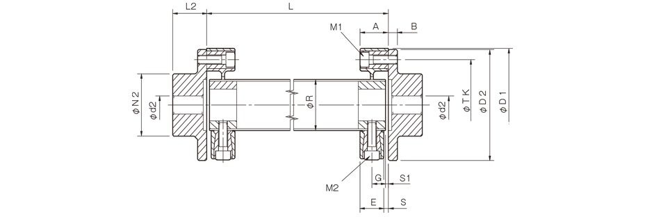
| Model | d2 | D1 | D2 | N2 | L2 | A | B | E | G | S | S1 | M1 | M2 | R | TK | ||
|---|---|---|---|---|---|---|---|---|---|---|---|---|---|---|---|---|---|
| Pilot bore | Min. | Max. | |||||||||||||||
| CF-X-001-OG | 8 | 9 | 22 | 57 | 56 | 36 | 24 | 24 | 7 | 18 | 11 | 3 | 1 | 2-M6 | 2-M6 | 30 | 44 |
| CF-X-002-OG | 9 | 10 | 30 | 88 | 85 | 45 | 28 | 24 | 8 | 20 | 10 | 4 | 4 | 2-M8 | 2-M8 | 40 | 68 |
| CF-X-004-OG | 11 | 12 | 36 | 100 | 100 | 55 | 30 | 25 | 8 | 21 | 12 | 4 | 2.5 | 3-M8 | 3-M8 | 45 | 80 |
| CF-X-008-OG | 15 | 16 | 46 | 125 | 120 | 70 | 42 | 30 | 10 | 26 | 14 | 4 | 3 | 3-M10 | 3-M10 | 60 | 100 |
| CF-X-016-OG | 19 | 20 | 56 | 155 | 150 | 85 | 50 | 35 | 12 | 28 | 18 | 7 | 3 | 3-M12 | 3-M12 | 70 | 125 |
| CF-X-025-OG | 19 | 20 | 65 | 175 | 170 | 100 | 56 | 40 | 14 | 34 | 20 | 6 | 3 | 3-M14 | 3-M14 | 85 | 140 |
*Pilot bores are to be drilled into the part. Minimum values for d2 are given by the minimum bore diameter values in the MIKI PULLEY standard hole-drilling standards and maximum values from the maximum allowable drilled bore diameters.
*The nominal diameters for bolts M1/M2 are equal to the quantity minus the nominal diameter of the screw threads, where the quantity is for one side.
*The L dimension has a standard length of 1000 mm or less. Dimension L must at least allow enough space for an M1 bolt to be mounted.

[Standard bore diameter]
| Model | Standard bore diameter [mm] | |||||||||||||||||
|---|---|---|---|---|---|---|---|---|---|---|---|---|---|---|---|---|---|---|
| 10 | 11 | 12 | 14 | 15 | 16 | 18 | 19 | 20 | 22 | 24 | 25 | 28 | 32 | 30 | 35 | 38 | ||
| CF-X-001-O2-C | d1 | ● | ● | ● | ● | ● | ● | |||||||||||
| d2 | ● | ● | ● | ● | ● | ● | ● | ● | ||||||||||
| CF-X-002-O2-C | d1 | ● | ● | ● | ● | ● | ● | ● | ● | ● | ● | |||||||
| d2 | ● | ● | ● | ● | ● | ● | ● | ● | ● | ● | ||||||||
| CF-X-004-O2-C | d1 | ● | ● | ● | ● | ● | ● | ● | ● | ● | ● | |||||||
| d2 | ● | ● | ● | ● | ● | ● | ● | ● | ● | ● | ● | ● | ● | ● | ||||
[Standard Hole-drilling Standards]
| Models compliant with the old JIS standard (class 2) JIS B 1301 1959 | Models compliant with the new JIS standard (H9) JIS B 1301 1996 | Models compliant with the motor standard JIS C 4210 2001 | ||||||||||||
|---|---|---|---|---|---|---|---|---|---|---|---|---|---|---|
| Nominal bore diameter | Bore diameter (d1, d2) | Keyway width (W1, W2) | Keyway height (T1, T2) | Set screw hole (M) | Nominal bore diameter | Bore diameter (d1, d2) | Keyway width (W1, W2) | Keyway height (T1, T2) | Set screw hole (M) | Nominal bore diameter | Bore diameter (d1, d2) | Keyway width (W1, W2) | Keyway height (T1, T2) | Set screw hole (M) |
| Tolerance H7, H8 | Tolerance E9 | - | Tolerance H7 | Tolerance H9 | - | Tolerance G7, F7 | Tolerance H9 | - | ||||||
| 9 | 9+0.0220 | - | - | 2-M4 | - | - | - | - | - | - | - | - | - | - |
| 10 | 10+0.0220 | - | - | 2-M4 | - | - | - | - | - | - | - | - | - | - |
| 11 | 11+0.0180 | - | - | 2-M4 | - | - | - | - | - | - | - | - | - | - |
| 12 | 12+0.0180 | 4+0.050+0.020 | 13.5+0.30 | 2-M4 | 12H | 12+0.0180 | 4+0.0300 | 13.8+0.30 | 2-M4 | - | - | - | - | - |
| 14 | 14+0.0180 | 5+0.050+0.020 | 16.0+0.30 | 2-M4 | 14H | 14+0.0180 | 5+0.0300 | 16.3+0.30 | 2-M4 | 14N | 14+0.024+0.006 | 5+0.0300 | 16.3+0.30 | 2-M4 |
| 15 | 15+0.0180 | 5+0.050+0.020 | 17.0+0.30 | 2-M4 | 15H | 15+0.0180 | 5+0.0300 | 17.3+0.30 | 2-M4 | - | - | - | - | - |
| 16 | 16+0.0180 | 5+0.050+0.020 | 18.0+0.30 | 2-M4 | 16H | 16+0.0180 | 5+0.0300 | 18.3+0.30 | 2-M4 | - | - | - | - | - |
| 17 | 17+0.0180 | 5+0.050+0.020 | 19.0+0.30 | 2-M4 | 17H | 17+0.0180 | 5+0.0300 | 19.3+0.30 | 2-M4 | - | - | - | - | - |
| 18 | 18+0.0180 | 5+0.050+0.020 | 20.0+0.30 | 2-M4 | 18H | 18+0.0180 | 6+0.0300 | 20.8+0.30 | 2-M5 | - | - | - | - | - |
| 19 | 19+0.0210 | 5+0.050+0.020 | 21.0+0.30 | 2-M4 | 19H | 19+0.0210 | 6+0.0300 | 21.8+0.30 | 2-M5 | 19N | 19+0.028+0.007 | 6+0.0300 | 21.8+0.30 | 2-M5 |
| 20 | 20+0.0210 | 5+0.050+0.020 | 22.0+0.30 | 2-M4 | 20H | 20+0.0210 | 6+0.0300 | 22.8+0.30 | 2-M5 | - | - | - | - | - |
| 22 | 22+0.0210 | 7+0.061+0.025 | 25.0+0.30 | 2-M6 | 22H | 22+0.0210 | 6+0.0300 | 24.8+0.30 | 2-M5 | - | - | - | - | - |
| 24 | 24+0.0210 | 7+0.061+0.025 | 27.0+0.30 | 2-M6 | 24H | 24+0.0210 | 8+0.0360 | 27.3+0.30 | 2-M6 | 24N | 24+0.028+0.007 | 8+0.0360 | 27.3+0.30 | 2-M6 |
| 25 | 25+0.0210 | 7+0.061+0.025 | 28.0+0.30 | 2-M6 | 25H | 25+0.0210 | 8+0.0360 | 28.3+0.30 | 2-M6 | - | - | - | - | - |
| 28 | 28+0.0210 | 7+0.061+0.025 | 31.0+0.30 | 2-M6 | 28H | 28+0.0210 | 8+0.0360 | 31.3+0.30 | 2-M6 | 28N | 28+0.028+0.007 | 8+0.0360 | 31.3+0.30 | 2-M6 |
| 30 | 30+0.0210 | 7+0.061+0.025 | 33.0+0.30 | 2-M6 | 30H | 30+0.0210 | 8+0.0360 | 33.3+0.30 | 2-M6 | - | - | - | - | - |
| 32 | 32+0.0250 | 10+0.061+0.025 | 35.5+0.30 | 2-M8 | 32H | 32+0.0250 | 10+0.0360 | 35.3+0.30 | 2-M8 | - | - | - | - | - |
| 35 | 35+0.0250 | 10+0.061+0.025 | 38.5+0.30 | 2-M8 | 35H | 35+0.0250 | 10+0.0360 | 38.3+0.30 | 2-M8 | - | - | - | - | - |
| 38 | 38+0.0250 | 10+0.061+0.025 | 41.5+0.30 | 2-M8 | 38H | 38+0.0250 | 10+0.0360 | 41.3+0.30 | 2-M8 | 38N | 38+0.050+0.025 | 10+0.0360 | 41.3+0.30 | 2-M8 |
| 40 | 40+0.0250 | 10+0.061+0.025 | 43.5+0.30 | 2-M8 | 40H | 40+0.0250 | 12+0.0430 | 43.3+0.30 | 2-M8 | - | - | - | - | - |
| 42 | 42+0.0250 | 12+0.075+0.032 | 45.5+0.30 | 2-M8 | 42H | 42+0.0250 | 12+0.0430 | 45.3+0.30 | 2-M8 | 42N | 42+0.050+0.025 | 12+0.0430 | 45.3+0.30 | 2-M8 |
| 45 | 45+0.0250 | 12+0.075+0.032 | 48.5+0.30 | 2-M8 | 45H | 45+0.0250 | 14+0.0430 | 48.8+0.30 | 2-M10 | - | - | - | - | - |
| 48 | 48+0.0250 | 12+0.075+0.032 | 51.5+0.30 | 2-M8 | 48H | 48+0.0250 | 14+0.0430 | 51.8+0.30 | 2-M10 | 48N | 48+0.050+0.025 | 14+0.0430 | 51.8+0.30 | 2-M10 |
| 50 | 50+0.0250 | 12+0.075+0.032 | 53.5+0.30 | 2-M8 | 50H | 50+0.0250 | 14+0.0430 | 53.8+0.30 | 2-M10 | - | - | - | - | - |
| 55 | 55+0.0300 | 15+0.075+0.032 | 60.0+0.30 | 2-M10 | 55H | 55+0.0300 | 16+0.0430 | 59.3+0.30 | 2-M10 | 55N | 55+0.060+0.030 | 16+0.0430 | 59.3+0.30 | 2-M10 |
| 56 | 56+0.0300 | 15+0.075+0.032 | 61.0+0.30 | 2-M10 | 56H | 56+0.0300 | 16+0.0430 | 60.3+0.30 | 2-M10 | - | - | - | - | - |
| 60 | 60+0.0300 | 15+0.075+0.032 | 65.0+0.30 | 2-M10 | 60H | 60+0.0300 | 18+0.0430 | 64.4+0.30 | 2-M10 | 60N | 60+0.060+0.030 | 18+0.0430 | 64.4+0.30 | 2-M10 |
| 63 | 63+0.0300 | 18+0.075+0.032 | 69.0+0.30 | 2-M10 | 18H | 63+0.0300 | 18+0.0430 | 67.4+0.30 | 2-M10 | - | - | - | - | - |
| 65 | 65+0.0300 | 18+0.075+0.032 | 71.0+0.30 | 2-M10 | 65H | 65+0.0300 | 18+0.0430 | 69.4+0.30 | 2-M10 | 65N | 65+0.060+0.030 | 18+0.0430 | 69.4+0.30 | 2-M10 |
*All standards starting from ø11 are the same as those in the old JIS standards column.
*Positions of set screws and keyways are not on the same plane.
*Set screws are included with the product.
*Positioning precision for keyway milling is determined by sight.
*Contact Miki Pulley when the keyway requires a positioning precision for a particular flange hub.
*Consult the technical documentation at the end of this volume for standard dimensions for bore drilling other than those given here.
[Set screw position (Cylinder hub)]
| Cylindrical hub model | Distance from edge[mm] |
|---|---|
| CF-X-001 | 6 |
| CF-X-002 | 6 |
| CF-X-004 | 6 |
| CF-X-008 | 7 |
| CF-X-016 | 10 |
| CF-X-025 | 10 |
[Set screw position (Flange hub)]
| Flange hub model | Distance from edge[mm] |
|---|---|
| CF-X-001 | 6 |
| CF-X-002 | 7 |
| CF-X-004 | 7 |
| CF-X-008 | 9 |
| CF-X-016 | 10 |
| CF-X-025 | 10 |
CF-X (O2-C) Types,*Made to order
[Specifications]
| Model | Torque | Misalignment | Max. rotation speed [min-1] | Static torsional stiffness [N・m/rad] | Moment of inertia [kg・m2] | Mass [kg] | |||
|---|---|---|---|---|---|---|---|---|---|
| Nominal [N・m] | Max. [N・m] | Parallel [mm] | Angular [°] | Axial [mm] | |||||
| CF-X-001-O2-C | 15 | 30 | 0.1 | 1 | ±0.5 | 10000 | 3.0×10³ | 7.14×10⁻⁵ | 0.2 |
| CF-X-002-O2-C | 30 | 60 | 0.1 | 1 | ±0.5 | 10000 | 6.0×10³ | 3.44×10⁻⁴ | 0.5 |
| CF-X-004-O2-C | 60 | 120 | 0.1 | 1 | ±0.5 | 8000 | 2.3×10⁴ | 7.22×10⁻⁴ | 0.7 |
*Max. rotation speed does not take into account dynamic balance.
*Static torsional stiffness values given are from measurements taken at 20℃ .
*Values for moment of inertia and mass are those when the cylindrical hub and flange hub have the minimum bore diameters.
[Dimensions]
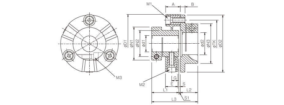
| Model | d1 | d2 | D1 | D2 | N1 | N2 | N3 | L1 | L2 | L3 | A | B | E | G | S | S1 | M1 | M2 | M3 | TK | ||
|---|---|---|---|---|---|---|---|---|---|---|---|---|---|---|---|---|---|---|---|---|---|---|
| Min. | Max. | Min. | Max. | |||||||||||||||||||
| CF-X-001-O2-C | 10 | 16 | 10 | 19 | 57 | 56 | 33 | 30 | 38 | 37 | 24 | 62 | 24 | 7 | 18 | 11 | 3 | 1 | 2-M6 | 2-M6 | 1-M5 | 44 |
| CF-X-002-O2-C | 12 | 25 | 12 | 25 | 88 | 85 | 46 | 40 | 46 | 43 | 28 | 75 | 24 | 8 | 20 | 10 | 4 | 4 | 2-M8 | 2-M8 | 1-M6 | 68 |
| CF-X-004-O2-C | 14 | 28 | 14 | 38 | 100 | 99 | 57 | 45 | 68 | 46.5 | 30 | 79 | 25 | 8 | 21 | 12 | 4 | 2.5 | 3-M8 | 3-M8 | 1-M8 | 80 |
*The nominal diameters for bolts M1, M2, and M3 are equal to the quantity minus the nominal diameter of the screw threads, where the quantity for clamping bolt M3 is for a hub on one side.
*The recommended processing tolerance for paired shafts is the h7 class.

[Standard bore diameter]
| Model | Standard bore diameter [mm] | |||||||||||||||||
|---|---|---|---|---|---|---|---|---|---|---|---|---|---|---|---|---|---|---|
| 10 | 11 | 12 | 14 | 15 | 16 | 18 | 19 | 20 | 22 | 24 | 25 | 28 | 32 | 30 | 35 | 38 | ||
| CF-X-001-O2-C | d1 | ● | ● | ● | ● | ● | ● | |||||||||||
| d2 | ● | ● | ● | ● | ● | ● | ● | ● | ||||||||||
| CF-X-002-O2-C | d1 | ● | ● | ● | ● | ● | ● | ● | ● | ● | ● | |||||||
| d2 | ● | ● | ● | ● | ● | ● | ● | ● | ● | ● | ||||||||
| CF-X-004-O2-C | d1 | ● | ● | ● | ● | ● | ● | ● | ● | ● | ● | |||||||
| d2 | ● | ● | ● | ● | ● | ● | ● | ● | ● | ● | ● | ● | ● | ● | ||||
[Standard Hole-drilling Standards]
| Models compliant with the old JIS standard (class 2) JIS B 1301 1959 | Models compliant with the new JIS standard (H9) JIS B 1301 1996 | Models compliant with the motor standard JIS C 4210 2001 | ||||||||||||
|---|---|---|---|---|---|---|---|---|---|---|---|---|---|---|
| Nominal bore diameter | Bore diameter (d1, d2) | Keyway width (W1, W2) | Keyway height (T1, T2) | Set screw hole (M) | Nominal bore diameter | Bore diameter (d1, d2) | Keyway width (W1, W2) | Keyway height (T1, T2) | Set screw hole (M) | Nominal bore diameter | Bore diameter (d1, d2) | Keyway width (W1, W2) | Keyway height (T1, T2) | Set screw hole (M) |
| Tolerance H7, H8 | Tolerance E9 | - | Tolerance H7 | Tolerance H9 | - | Tolerance G7, F7 | Tolerance H9 | - | ||||||
| 9 | 9+0.0220 | - | - | 2-M4 | - | - | - | - | - | - | - | - | - | - |
| 10 | 10+0.0220 | - | - | 2-M4 | - | - | - | - | - | - | - | - | - | - |
| 11 | 11+0.0180 | - | - | 2-M4 | - | - | - | - | - | - | - | - | - | - |
| 12 | 12+0.0180 | 4+0.050+0.020 | 13.5+0.30 | 2-M4 | 12H | 12+0.0180 | 4+0.0300 | 13.8+0.30 | 2-M4 | - | - | - | - | - |
| 14 | 14+0.0180 | 5+0.050+0.020 | 16.0+0.30 | 2-M4 | 14H | 14+0.0180 | 5+0.0300 | 16.3+0.30 | 2-M4 | 14N | 14+0.024+0.006 | 5+0.0300 | 16.3+0.30 | 2-M4 |
| 15 | 15+0.0180 | 5+0.050+0.020 | 17.0+0.30 | 2-M4 | 15H | 15+0.0180 | 5+0.0300 | 17.3+0.30 | 2-M4 | - | - | - | - | - |
| 16 | 16+0.0180 | 5+0.050+0.020 | 18.0+0.30 | 2-M4 | 16H | 16+0.0180 | 5+0.0300 | 18.3+0.30 | 2-M4 | - | - | - | - | - |
| 17 | 17+0.0180 | 5+0.050+0.020 | 19.0+0.30 | 2-M4 | 17H | 17+0.0180 | 5+0.0300 | 19.3+0.30 | 2-M4 | - | - | - | - | - |
| 18 | 18+0.0180 | 5+0.050+0.020 | 20.0+0.30 | 2-M4 | 18H | 18+0.0180 | 6+0.0300 | 20.8+0.30 | 2-M5 | - | - | - | - | - |
| 19 | 19+0.0210 | 5+0.050+0.020 | 21.0+0.30 | 2-M4 | 19H | 19+0.0210 | 6+0.0300 | 21.8+0.30 | 2-M5 | 19N | 19+0.028+0.007 | 6+0.0300 | 21.8+0.30 | 2-M5 |
| 20 | 20+0.0210 | 5+0.050+0.020 | 22.0+0.30 | 2-M4 | 20H | 20+0.0210 | 6+0.0300 | 22.8+0.30 | 2-M5 | - | - | - | - | - |
| 22 | 22+0.0210 | 7+0.061+0.025 | 25.0+0.30 | 2-M6 | 22H | 22+0.0210 | 6+0.0300 | 24.8+0.30 | 2-M5 | - | - | - | - | - |
| 24 | 24+0.0210 | 7+0.061+0.025 | 27.0+0.30 | 2-M6 | 24H | 24+0.0210 | 8+0.0360 | 27.3+0.30 | 2-M6 | 24N | 24+0.028+0.007 | 8+0.0360 | 27.3+0.30 | 2-M6 |
| 25 | 25+0.0210 | 7+0.061+0.025 | 28.0+0.30 | 2-M6 | 25H | 25+0.0210 | 8+0.0360 | 28.3+0.30 | 2-M6 | - | - | - | - | - |
| 28 | 28+0.0210 | 7+0.061+0.025 | 31.0+0.30 | 2-M6 | 28H | 28+0.0210 | 8+0.0360 | 31.3+0.30 | 2-M6 | 28N | 28+0.028+0.007 | 8+0.0360 | 31.3+0.30 | 2-M6 |
| 30 | 30+0.0210 | 7+0.061+0.025 | 33.0+0.30 | 2-M6 | 30H | 30+0.0210 | 8+0.0360 | 33.3+0.30 | 2-M6 | - | - | - | - | - |
| 32 | 32+0.0250 | 10+0.061+0.025 | 35.5+0.30 | 2-M8 | 32H | 32+0.0250 | 10+0.0360 | 35.3+0.30 | 2-M8 | - | - | - | - | - |
| 35 | 35+0.0250 | 10+0.061+0.025 | 38.5+0.30 | 2-M8 | 35H | 35+0.0250 | 10+0.0360 | 38.3+0.30 | 2-M8 | - | - | - | - | - |
| 38 | 38+0.0250 | 10+0.061+0.025 | 41.5+0.30 | 2-M8 | 38H | 38+0.0250 | 10+0.0360 | 41.3+0.30 | 2-M8 | 38N | 38+0.050+0.025 | 10+0.0360 | 41.3+0.30 | 2-M8 |
| 40 | 40+0.0250 | 10+0.061+0.025 | 43.5+0.30 | 2-M8 | 40H | 40+0.0250 | 12+0.0430 | 43.3+0.30 | 2-M8 | - | - | - | - | - |
| 42 | 42+0.0250 | 12+0.075+0.032 | 45.5+0.30 | 2-M8 | 42H | 42+0.0250 | 12+0.0430 | 45.3+0.30 | 2-M8 | 42N | 42+0.050+0.025 | 12+0.0430 | 45.3+0.30 | 2-M8 |
| 45 | 45+0.0250 | 12+0.075+0.032 | 48.5+0.30 | 2-M8 | 45H | 45+0.0250 | 14+0.0430 | 48.8+0.30 | 2-M10 | - | - | - | - | - |
| 48 | 48+0.0250 | 12+0.075+0.032 | 51.5+0.30 | 2-M8 | 48H | 48+0.0250 | 14+0.0430 | 51.8+0.30 | 2-M10 | 48N | 48+0.050+0.025 | 14+0.0430 | 51.8+0.30 | 2-M10 |
| 50 | 50+0.0250 | 12+0.075+0.032 | 53.5+0.30 | 2-M8 | 50H | 50+0.0250 | 14+0.0430 | 53.8+0.30 | 2-M10 | - | - | - | - | - |
| 55 | 55+0.0300 | 15+0.075+0.032 | 60.0+0.30 | 2-M10 | 55H | 55+0.0300 | 16+0.0430 | 59.3+0.30 | 2-M10 | 55N | 55+0.060+0.030 | 16+0.0430 | 59.3+0.30 | 2-M10 |
| 56 | 56+0.0300 | 15+0.075+0.032 | 61.0+0.30 | 2-M10 | 56H | 56+0.0300 | 16+0.0430 | 60.3+0.30 | 2-M10 | - | - | - | - | - |
| 60 | 60+0.0300 | 15+0.075+0.032 | 65.0+0.30 | 2-M10 | 60H | 60+0.0300 | 18+0.0430 | 64.4+0.30 | 2-M10 | 60N | 60+0.060+0.030 | 18+0.0430 | 64.4+0.30 | 2-M10 |
| 63 | 63+0.0300 | 18+0.075+0.032 | 69.0+0.30 | 2-M10 | 18H | 63+0.0300 | 18+0.0430 | 67.4+0.30 | 2-M10 | - | - | - | - | - |
| 65 | 65+0.0300 | 18+0.075+0.032 | 71.0+0.30 | 2-M10 | 65H | 65+0.0300 | 18+0.0430 | 69.4+0.30 | 2-M10 | 65N | 65+0.060+0.030 | 18+0.0430 | 69.4+0.30 | 2-M10 |
*All standards starting from ø11 are the same as those in the old JIS standards column.
*Positions of set screws and keyways are not on the same plane.
*Set screws are included with the product.
*Positioning precision for keyway milling is determined by sight.
*Contact Miki Pulley when the keyway requires a positioning precision for a particular flange hub.
*Consult the technical documentation at the end of this volume for standard dimensions for bore drilling other than those given here.
[Set screw position (Cylinder hub)]
| Cylindrical hub model | Distance from edge[mm] |
|---|---|
| CF-X-001 | 6 |
| CF-X-002 | 6 |
| CF-X-004 | 6 |
| CF-X-008 | 7 |
| CF-X-016 | 10 |
| CF-X-025 | 10 |
[Set screw position (Flange hub)]
| Flange hub model | Distance from edge[mm] |
|---|---|
| CF-X-001 | 6 |
| CF-X-002 | 7 |
| CF-X-004 | 7 |
| CF-X-008 | 9 |
| CF-X-016 | 10 |
| CF-X-025 | 10 |
![]()
![]()
![]()
![]()
![]()
![]()