日本語
日本語 English
 Deutsch
 中文
中文 한국어
한국어


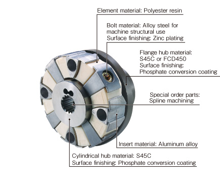
CF-H Models

![]()
CF-H (O0/O1/O2) Types
[Specifications]
| Model | Torque | Misalignment | Max. rotation speed [min-1] | Dynamic torsional stiffness [N・m/rad] | |||
|---|---|---|---|---|---|---|---|
| Nominal [N・m] | Max. [N・m] | Parallel [mm] | Angular [°] | Axial [mm] | |||
| CF-H-008 | 100 | 200 | 0.3 | 0.5 | ± 3 | 6500 | 1.27×10⁴ |
| CF-H-016 | 200 | 400 | 0.3 | 0.5 | ± 3 | 5500 | 2.46×10⁴ |
| CF-H-030 | 400 | 800 | 0.4 | 0.5 | ± 3 | 4000 | 5.91×10⁴ |
| CF-H-040 | 600 | 1200 | 0.4 | 0.5 | ± 3 | 4000 | 1.87×10⁵ |
| CF-H-050 | 800 | 1600 | 0.4 | 0.5 | ± 3 | 4000 | 1.91×10⁵ |
| CF-H-090 | 950 | 1900 | 0.4 | 0.5 | ± 3 | 4000 | 2.69×10⁵ |
| CF-H-110 | 1100 | 2200 | 0.4 | 0.5 | ± 3 | 4000 | 2.79×10⁵ |
| CF-H-160 | 1600 | 3200 | 0.4 | 0.5 | ± 3 | 3600 | 5.11×10⁵ |
| CF-H-240 | 2500 | 5000 | 0.4 | 0.5 | ± 3 | 3000 | 5.10×10⁵ |
| Model | Moment of inertia [kg・m2] | Mass [kg] |
|---|---|---|
| CF-H-008-O0 | 9.4×10⁻⁴ | 0.4 |
| CF-H-016-O0 | 3.0×10⁻³ | 0.8 |
| CF-H-030-O0 | 9.2×10⁻³ | 1.5 |
| CF-H-040-O0 | 6.9×10⁻³ | 1.4 |
| CF-H-050-O0 | 1.2×10⁻² | 1.8 |
| CF-H-090-O0 | 1.5×10⁻² | 2.3 |
| CF-H-110-O0 | 2.3×10⁻² | 2.8 |
| CF-H-160-O0 | 3.6×10⁻² | 3.4 |
| CF-H-240-O0 | 0.10 | 5.8 |
| Model | Moment of inertia [kg・m2] | Mass [kg] |
|---|---|---|
| CF-H-008-O1 | 1.8×10⁻³ | 1.3 |
| CF-H-016-O1 | 4.9×10⁻³ | 2.5 |
| CF-H-030-O1 | 1.9×10⁻² | 6.0 |
| CF-H-040-O1 | 1.3×10⁻² | 4.4 |
| CF-H-050-O1 | 2.3×10⁻² | 6.5 |
| CF-H-090-O1 | 2.6×10⁻² | 6.9 |
| CF-H-110-O1 | 3.7×10⁻² | 9.7 |
| CF-H-160-O1 | 7.0×10⁻² | 11.9 |
| CF-H-240-O1 | 0.18 | 20.9 |
| Model | Moment of inertia [kg・m2] | Mass [kg] |
|---|---|---|
| CF-H-008-O2 | 3.9×10⁻³ | 3.1 |
| CF-H-016-O2 | 1.1×10⁻² | 5.6 |
| CF-H-030-O2 | 4.6×10⁻² | 13.9 |
| CF-H-040-O2 | 2.8×10⁻² | 9.8 |
| CF-H-050-O2 | 5.0×10⁻² | 14.4 |
| CF-H-090-O2 | 5.3×10⁻² | 14.8 |
| CF-H-110-O2 | 8.2×10⁻² | 18.3 |
| CF-H-160-O2 | 0.16 | 26.1 |
| CF-H-240-O2 | 0.39 | 48.8 |
*Max. rotation speed does not take into account dynamic balance.
*Dynamic torsion spring characteristics are non-linear, so use a dynamic torsional stiffness that is at least roughly 20% of rated torque.
*The dynamic torsional stiffness is about 1.3 times that of the static torsional stiffness.
*Values for moment of inertia and mass are those when the cylindrical hub and flange hub have pilot bores.
[Dimensions]
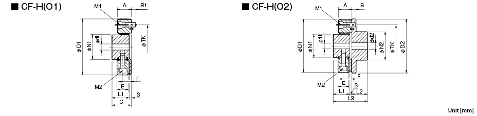
| Model | d1 | d2 | D1 | D2 | N1 | N2 | L1 | L2 | L3 | A | B | B1 | C | E | F | S | TK | M1 | M2 | ||||
|---|---|---|---|---|---|---|---|---|---|---|---|---|---|---|---|---|---|---|---|---|---|---|---|
| Pilot bore | Min. | Max. | Pilot bore | Min. | Max. | ||||||||||||||||||
| CF-H-008 | 12 | 14 | 38 | 15 | 16 | 46 | 125 | 120 | 60 | 70 | 40 | 42 | 88 | 32 | 10 | 10 | 46 | 25 | 20 | 6 | 100 | 3-M10 | 3-M10 |
| CF-H-016 | 15 | 16 | 48 | 19 | 20 | 56 | 155 | 150 | 70 | 85 | 52 | 50 | 110 | 41 | 12 | 12 | 60 | 34 | 26 | 8 | 125 | 3-M12 | 3-M12 |
| CF-H-030 | 20 | 22 | 65 | 28 | 30 | 80 | 205 | 200 | 100 | 120 | 68 | 66 | 144 | 56 | 16 | 15 | 78 | 46 | 35 | 10 | 165 | 3-M16 | 3-M16 |
| CF-H-040 | 22 | 24 | 50 | 22 | 24 | 65 | 175 | 180 | 85 | 100 | 58 | 56 | 124 | 50 | 16 | 16 | 68 | 42 | 31 | 10 | 140 | 4-M16 | 4-M16 |
| CF-H-050 | 20 | 22 | 65 | 28 | 30 | 80 | 205 | 200 | 100 | 120 | 68 | 66 | 144 | 56 | 16 | 15 | 78 | 46 | 35 | 10 | 165 | 4-M16 | 4-M16 |
| CF-H-090 | 20 | 22 | 65 | 28 | 30 | 80 | 215 | 200 | 100 | 120 | 68 | 66 | 144 | 56 | 16 | 15 | 78 | 46 | 35 | 10 | 165 | 4-M16 | 4-M16 |
| CF-H-110 | 25 | 28 | 63 | 28 | 30 | 80 | 225 | 230 | 100 | 120 | 68 | 66 | 144 | 56 | 18 | 18 | 78 | 46 | 35 | 10 | 180 | 4-M18 | 4-M18 |
| CF-H-160 | 30 | 32 | 85 | 30 | 32 | 95 | 270 | 260 | 125 | 140 | 84 | 80 | 177 | 59 | 19 | 20 | 97 | 48 | 37 | 13 | 215 | 4-M20 | 4-M20 |
| CF-H-240 | 40 | 42 | 115 | 40 | 42 | 120 | 330 | 320 | 160 | 180 | 100 | 100 | 213 | 65 | 19 | 20 | 113 | 54 | 40 | 13 | 260 | 4-M20 | 4-M20 |
*Pilot bores are to be drilled into the part. Minimum values for d1 and d2 are given by the minimum bore diameter values in the MIKI PULLEY standard hole-drilling standards and maximum values from the maximum allowable drilled bore diameters.
*The TK dimension is the bolt mounting pitch diameter of the fl ange hub or paired mounting part.

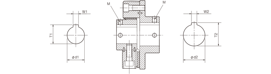
[Standard Hole-drilling Standards]
| Models compliant with the old JIS standard (class 2) JIS B 1301 1959 | Models compliant with the new JIS standard (H9) JIS B 1301 1996 | Models compliant with the motor standard JIS C 4210 2001 | ||||||||||||
|---|---|---|---|---|---|---|---|---|---|---|---|---|---|---|
| Nominal bore diameter | Bore diameter (d1, d2) | Keyway width (W1, W2) | Keyway height (T1, T2) | Set screw hole (M) | Nominal bore diameter | Bore diameter (d1, d2) | Keyway width (W1, W2) | Keyway height (T1, T2) | Set screw hole (M) | Nominal bore diameter | Bore diameter (d1, d2) | Keyway width (W1, W2) | Keyway height (T1, T2) | Set screw hole (M) |
| Tolerance H7 | Tolerance E9 | - | Tolerance H7 | Tolerance H9 | - | Tolerance G7, F7 | Tolerance H9 | - | ||||||
| 14 | 14+0.0180 | 5+0.050+0.020 | 16.0+0.30 | 2-M4 | 14H | 14+0.0180 | 5+0.0300 | 16.3+0.30 | 2-M4 | 14N | 14+0.024+0.006 | 5+0.0300 | 16.3+0.30 | 2-M4 |
| 15 | 15+0.0180 | 5+0.050+0.020 | 17.0+0.30 | 2-M4 | 15H | 15+0.0180 | 5+0.0300 | 17.3+0.30 | 2-M4 | - | - | - | - | - |
| 16 | 16+0.0180 | 5+0.050+0.020 | 18.0+0.30 | 2-M4 | 16H | 16+0.0180 | 5+0.0300 | 18.3+0.30 | 2-M4 | - | - | - | - | - |
| 17 | 17+0.0180 | 5+0.050+0.020 | 19.0+0.30 | 2-M4 | 17H | 17+0.0180 | 5+0.0300 | 19.3+0.30 | 2-M4 | - | - | - | - | - |
| 18 | 18+0.0180 | 5+0.050+0.020 | 20.0+0.30 | 2-M4 | 18H | 18+0.0180 | 6+0.0300 | 20.8+0.30 | 2-M5 | - | - | - | - | - |
| 19 | 19+0.0210 | 5+0.050+0.020 | 21.0+0.30 | 2-M4 | 19H | 19+0.0210 | 6+0.0300 | 21.8+0.30 | 2-M5 | 19N | 19+0.028+0.007 | 6+0.0300 | 21.8+0.30 | 2-M5 |
| 20 | 20+0.0210 | 5+0.050+0.020 | 22.0+0.30 | 2-M4 | 20H | 20+0.0210 | 6+0.0300 | 22.8+0.30 | 2-M5 | - | - | - | - | - |
| 22 | 22+0.0210 | 7+0.061+0.025 | 25.0+0.30 | 2-M6 | 22H | 22+0.0210 | 6+0.0300 | 24.8+0.30 | 2-M5 | - | - | - | - | - |
| 24 | 24+0.0210 | 7+0.061+0.025 | 27.0+0.30 | 2-M6 | 24H | 24+0.0210 | 8+0.0360 | 27.3+0.30 | 2-M6 | 24N | 24+0.028+0.007 | 8+0.0360 | 27.3+0.30 | 2-M6 |
| 25 | 25+0.0210 | 7+0.061+0.025 | 28.0+0.30 | 2-M6 | 25H | 25+0.0210 | 8+0.0360 | 28.3+0.30 | 2-M6 | - | - | - | - | - |
| 28 | 28+0.0210 | 7+0.061+0.025 | 31.0+0.30 | 2-M6 | 28H | 28+0.0210 | 8+0.0360 | 31.3+0.30 | 2-M6 | 28N | 28+0.028+0.007 | 8+0.0360 | 31.3+0.30 | 2-M6 |
| 30 | 30+0.0210 | 7+0.061+0.025 | 33.0+0.30 | 2-M6 | 30H | 30+0.0210 | 8+0.0360 | 33.3+0.30 | 2-M6 | - | - | - | - | - |
| 32 | 32+0.0250 | 10+0.061+0.025 | 35.5+0.30 | 2-M8 | 32H | 32+0.0250 | 10+0.0360 | 35.3+0.30 | 2-M8 | - | - | - | - | - |
| 35 | 35+0.0250 | 10+0.061+0.025 | 38.5+0.30 | 2-M8 | 35H | 35+0.0250 | 10+0.0360 | 38.3+0.30 | 2-M8 | - | - | - | - | - |
| 38 | 38+0.0250 | 10+0.061+0.025 | 41.5+0.30 | 2-M8 | 38H | 38+0.0250 | 10+0.0360 | 41.3+0.30 | 2-M8 | 38N | 38+0.050+0.025 | 10+0.0360 | 41.3+0.30 | 2-M8 |
| 40 | 40+0.0250 | 10+0.061+0.025 | 43.5+0.30 | 2-M8 | 40H | 40+0.0250 | 12+0.0430 | 43.3+0.30 | 2-M8 | - | - | - | - | - |
| 42 | 42+0.0250 | 12+0.075+0.032 | 45.5+0.30 | 2-M8 | 42H | 42+0.0250 | 12+0.0430 | 45.3+0.30 | 2-M8 | 42N | 42+0.050+0.025 | 12+0.0430 | 45.3+0.30 | 2-M8 |
| 45 | 45+0.0250 | 12+0.075+0.032 | 48.5+0.30 | 2-M8 | 45H | 45+0.0250 | 14+0.0430 | 48.8+0.30 | 2-M10 | - | - | - | - | - |
| 48 | 48+0.0250 | 12+0.075+0.032 | 51.5+0.30 | 2-M8 | 48H | 48+0.0250 | 14+0.0430 | 51.8+0.30 | 2-M10 | 48N | 48+0.050+0.025 | 14+0.0430 | 51.8+0.30 | 2-M10 |
| 50 | 50+0.0250 | 12+0.075+0.032 | 53.5+0.30 | 2-M8 | 50H | 50+0.0250 | 14+0.0430 | 53.8+0.30 | 2-M10 | - | - | - | - | - |
| 55 | 55+0.0300 | 15+0.075+0.032 | 60.0+0.30 | 2-M10 | 55H | 55+0.0300 | 16+0.0430 | 59.3+0.30 | 2-M10 | 55N | 55+0.060+0.030 | 16+0.0430 | 59.3+0.30 | 2-M10 |
| 56 | 56+0.0300 | 15+0.075+0.032 | 61.0+0.30 | 2-M10 | 56H | 56+0.0300 | 16+0.0430 | 60.3+0.30 | 2-M10 | - | - | - | - | - |
| 60 | 60+0.0300 | 15+0.075+0.032 | 65.0+0.30 | 2-M10 | 60H | 60+0.0300 | 18+0.0430 | 64.4+0.30 | 2-M10 | 60N | 60+0.060+0.030 | 18+0.0430 | 64.4+0.30 | 2-M10 |
| 63 | 63+0.0300 | 18+0.075+0.032 | 69.0+0.30 | 2-M10 | 18H | 63+0.0300 | 18+0.0430 | 67.4+0.30 | 2-M10 | - | - | - | - | - |
| 65 | 65+0.0300 | 18+0.075+0.032 | 71.0+0.30 | 2-M10 | 65H | 65+0.0300 | 18+0.0430 | 69.4+0.30 | 2-M10 | 65N | 65+0.060+0.030 | 18+0.0430 | 69.4+0.30 | 2-M10 |
*Positions of set screws and keyways are not on the same plane.
*Set screws are included with the product.
*Positioning precision for keyway milling is determined by sight.
*Contact Miki Pulley when the keyway requires a positioning precision for a particular flange hub.
*Consult the technical documentation at the end of this volume for standard dimensions for bore drilling other than those given here.
*We can also machine splines. Please contact Miki Pulley.
[Set screw position (Cylinder hub)]
| Cylindrical hub coupling size | Distance from edge[mm] |
|---|---|
| 008 | 7 |
| 016 | 10 |
| 030 | 11 |
| 040 | 10 |
| 050・090・110 | 11 |
| 160・240 | 15 |
[Set screw position (Flange hub)]
| Flange hub coupling size | Distance from edge[mm] |
|---|---|
| 008 | 9 |
| 016 | 10 |
| 030 | 15 |
| 040 | 10 |
| 050・090・110 | 15 |
| 160・240 | 15 |
![]()
![]()
![]()
![]()
![]()
![]()