日本語
日本語 English
 Deutsch
 中文
中文 한국어
한국어


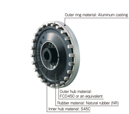
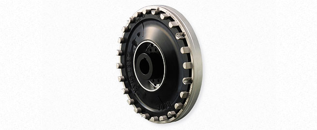
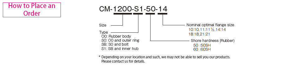
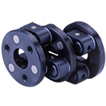
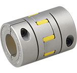
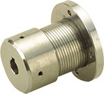
CM Models

![]()
CM Models,*Made to order
[Specifications]
| Model | Shore hardness 50SH Torque | Shore hardness 50SH Dynamic torsional stiffness [N・m/rad] | Shore hardness 60SH Torque | Shore hardness 60SH Dynamic torsional stiffness [N・m/rad] | Misalignment | Max. rotation speed [min-1] | Compatible flange size SAE J620 | ||||||
|---|---|---|---|---|---|---|---|---|---|---|---|---|---|
| Nominal [N・m] | Max. [N・m] | Continuous vibration torque [N・m/10Hz] | Nominal [N・m] | Max. [N・m] | Continuous vibration torque [N・m/10Hz] | Parallel [mm] | Angular [°] | ||||||
| CM-800-S1 | 700 | 1400 | 280 | 2.80×10³ | 850 | 1700 | 340 | 4.20×10³ | 0.5 | 0.5 | 3600 | 10・11 1/2・14 | |
| CM-1200-S1 | 1000 | 2000 | 400 | 4.50×10³ | 1200 | 2400 | 480 | 7.00×10³ | 0.5 | 0.5 | 3500 | 11 1/2・14 | |
| CM-2400-S1 | 2000 | 4000 | 800 | 1.00×10⁴ | 2500 | 5000 | 1000 | 1.50×10⁴ | 0.5 | 0.5 | 3000 | 14 | |
| CM-2800-S1 | 2800 | 6000 | 1120 | 2.50×10⁴ | 3000 | 7500 | 1200 | 3.75×10⁴ | 0.5 | 0.5 | 3000 | 14 | |
| CM-3000-S1 | 3000 | 6000 | 1200 | 1.00×10⁴ | 3300 | 7000 | 1300 | 1.51×10⁴ | 0.5 | 0.5 | 3000 | 14・18 | |
| CM-3500-S1 | 3200 | 6500 | 1280 | 1.60×10⁴ | 3500 | 8000 | 1400 | 2.40×10⁴ | 0.5 | 0.5 | 3000 | 14・18 | |
| CM-4000-S1 | - | - | - | - | 4500 | 11000 | 1800 | 5.00×10⁴ | 0.5 | 0.5 | 3000 | 14・18 | |
| CM-5000-S1 | 4500 | 9000 | 1800 | 1.70×10⁴ | 5000 | 10000 | 2000 | 2.70×10⁴ | 0.5 | 0.5 | 3000 | 14・18 | |
| CM-7000-S1 | 6300 | 12600 | 2520 | 2.85×10⁴ | 7000 | 14000 | 2800 | 4.50×10⁴ | 0.5 | 0.5 | 2500 | 18 | |
| CM-8000-S1 | - | - | - | - | 9000 | 22000 | 3600 | 8.00×10⁴ | 0.5 | 0.5 | 2500 | 18・21 | |
| CM-18000-S1 | 16000 | 32000 | 6400 | 1.15×10⁵ | 18000 | 36000 | 7200 | 1.70×10⁵ | 0.5 | 0.5 | 2300 | 21 | |
*Max. rotation speed is for the minimum flange size.This also does not take into account dynamic balance.
[Dimensions]
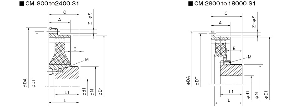
| Model | Compatible flange size SAE J620 | A | C | d1 | D1 | E | L | L1 | N | M | |
|---|---|---|---|---|---|---|---|---|---|---|---|
| Pilot bore | Max. | ||||||||||
| CM-800 | 10 | 50 | 82±2 | 18 | 70 | 316 | 18 | 84 | 66 | 107 | 8-M10 |
| 111/2 | 39 | 71±3 | 18 | 70 | 318 | 18 | 84 | 66 | 107 | 8-M10 | |
| 14 | 46 | 74±6 | 18 | 70 | 318 | 18 | 84 | 66 | 107 | 8-M10 | |
| CM-1200 | 111/2 | 39 | 65±4 | 18 | 70 | 318 | 18 | 84 | 66 | 107 | 8-M10 |
| 14 | 46 | 74±1 | 18 | 70 | 318 | 18 | 84 | 66 | 107 | 8-M10 | |
| CM-2400 | 61 | 85+8-2 | 28 | 105 | 417 | 16 | 96 | 75 | 150 | 8-M12 | |
| CM-2800 | 61 | 130±4 | 33 | 110 | 417 | 71 | 126 | 100 | 162 | 8-M16 | |
| CM-3000 | 14・18 | 70 | 135±8 | 19 | 65 | 465 | 53 | 135 | 105 | 100 | 12-M12 |
| CM-3500 | 14・18 | 70 | 135±6 | 33 | 110 | 465 | 59 | 139 | 100 | 162 | 8-M16 |
| CM-4000 | 14・18 | 70 | 161±6 | 48 | 140 | 465 | 94 | 159 | 125 | 218 | 12-M16 |
| CM-5000 | 14・18 | 70 | 147±2 | 35 | 110 | 465 | 64 | 159 | 105 | 162 | 12-M16 |
| CM-7000 | 18 | 80 | 159±9 | 48 | 140 | 570 | 76 | 161 | 125 | 218 | 12-M16 |
| CM-8000 | 18 | 90 | 197±5 | 68 | 175 | 600 | 110 | 195 | 150 | 248 | 12-M20 |
| 21 | 197±5 | 68 | 175 | 584 | 110 | 195 | 150 | 248 | 12-M20 | ||
| CM-18000 | 141 | 310±9 | 70 | 680 | 176 | 306 | 200 | 24-M20 | |||
| Nominal compatible flange size | 10 | 11 | 14 | 18 | 21 |
|---|---|---|---|---|---|
| Compatible flange size SAE J620 | 10 | 111/2 | 14 | 18 | 21 |
| DA | 314.3 | 352.4 | 466.7 | 571.5 | 673.1 |
| DT | 295.3 | 333.4 | 438.2 | 542.9 | 641.4 |
| Z | 8×45° | 8×45° | 8×45° | 6×60° | 12×30° |
| S | 11 | 11 | 13 | 17 | 17 |
*The dimensions of the outer ring on the drive side are for mounting directly on an SAE J620 flywheel.
![]()
![]()
![]()
![]()
![]()
![]()