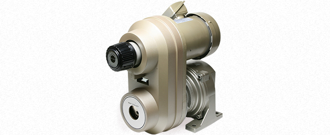
![]()
Options of ANG Models
Weight Type Index SD
A rotation speed indicator (SD model) can be built in the standard handle part.
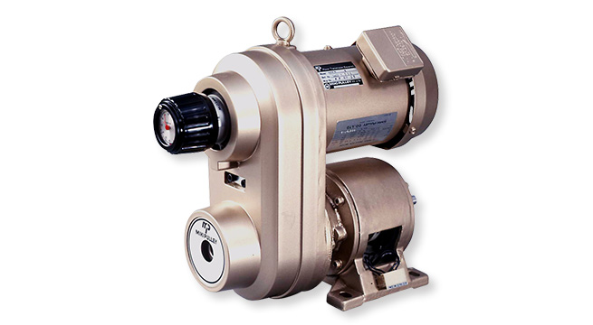
| Model | Number of handle turns | SD model for AN |
|---|---|---|
| AN□-02-SD | 5 | SD-53B-B544 |
| AN□-04-SD | 6 | SD-53B-B545 |
| AN□-07-SD | 7 | SD-53B-B546 |
| AN□-15-SD | 8.25 | SD-53B-B547 |
| AN□-22-SD | 8.25 | SD-53B-B548 |
| AN□-37-SD | 8.75 | SD-53B-B549 |
*A red zone corresponding to the number of turns of the handle is provided for the SD model for AN.
Handle Mounting Square Hole for Adjustment during Stop TH
Fine adjustments and positioning can be performed easily by using the handle inserted to this hole during machine stop.
Mount the adjustment handle for adjustment during stop TH to the square hole bushing of the PE model speed change pulley to perform fine adjustments and positioning.
* Please order an adjustment handle for adjustment during stop (TH-125-12) separately.
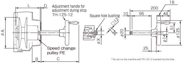
[When the AN unit is mounted]
| Model | A | B | C | D | L | X |
|---|---|---|---|---|---|---|
| AN□-02-TH | 106 | 40 | 188 | 2 | 101 | 20 |
| AN□-04-TH | 125 | 44 | 188 | 2 | 122 | 20 |
| AN□-07-TH | 155 | 42 | 188 | 2 | 124 | 20 |
| AN□-15-TH | 185 | 53 | 185 | 5 | 151 | 20 |
| AN□-22-TH | 185 | 57 | 188 | 2 | 164 | 20 |
| AN□-37-TH | 216 | 74 | 189 | 1 | 175 | 20 |
[When the ACW unit is mounted]
| Model | A | B | C | D | L | X |
|---|---|---|---|---|---|---|
| ACW-02PMN-TH | 106 | 57 | 207 | -17 | 136.5 | 20 |
| ACW-04PMN-TH | 125 | 49 | 198.5 | -8.5 | 137.5 | 34 |
| ACW-07PMN-TH | 155 | 53 | 202 | -12 | 150 | 20 |
| ACW-15PMN-TH | 185 | 60 | 197.5 | -7.5 | 170.5 | 20 |
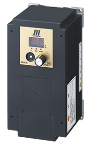
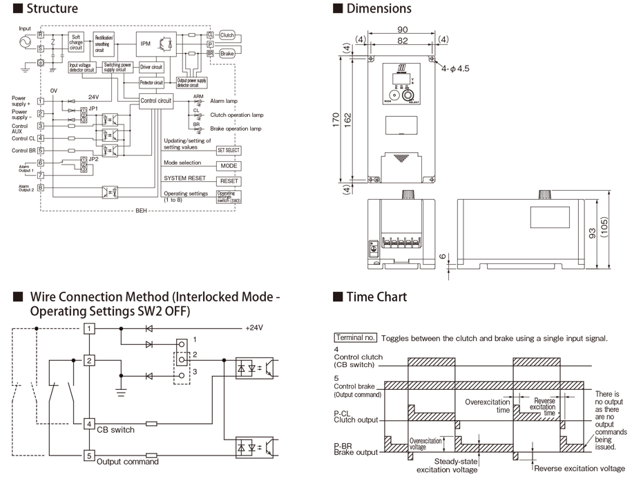
Electromagnetic Clutch and Brake Power Supply Unit BEH
Just connect the device to the AC outlet power supply (100/200 VAC) to receive the 24 VDC excitation power supply necessary for the electromagnetic clutch and brake. In particular, a combination mode to interlock the electromagnetic clutch and the electromagnetic brake enables high-accuracy and high-speed operation. The highperformance power supply also includes an auto-tuning function to automatically detect the connected electromagnetic clutch and brake and set the optimal operating conditions, as well as a variety of protection functions; for example, wiring, connection, and setting errors are indicated by an alarm sound to allow the user to easily remove the cause of the error.
| Applicable unit | Power supply unit model | Input voltage [V] | Output voltage [V] | Output capacity [W] |
|---|---|---|---|---|
| ACW / ANB Common to all models | BEH-10G | AC200/220 ± 10% | DC24 | 50 |
| BEH-20G-1 | AC100/115 ± 10% | DC24 | 100 |
Related Product
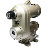
- Motor output 0.2 kW to 3.7 kW (4-pole)
- Power supply voltage Three-phase 200 V/50 Hz, 200 or 220 V/60 Hz
- Speed reduction ratios 1/10, 1/20, 1/30, 1/40, 1/50, 1/60
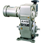
- Motor output 0.2 kW to 3.7 kW (4-pole)
- Power supply voltage Three-phase 200 V/50 Hz, 200 V or 220 V/60 Hz
- CB torque 5.5 N・m to 90 N・m

- Motor output 0.2 kW to 1.5 kW (4-pole)
- Power supply voltage Three-phase 200 V/50 Hz, 200 or 220 V/60 Hz
- Speed reduction ratios 1/10, 1/20, 1/30, 1/40, 1/50, 1/60
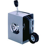
- Transmitted capacity 0.2 kW to 2.2 kW
- Speed change ratio 1:2 to 1:4
- Outer diameter of pulley 103 mm to 260 mm
 日本語
日本語 English
 Deutsch
 中文
中文 한국어
한국어


