日本語
日本語 English
 Deutsch
 中文
中文 한국어
한국어


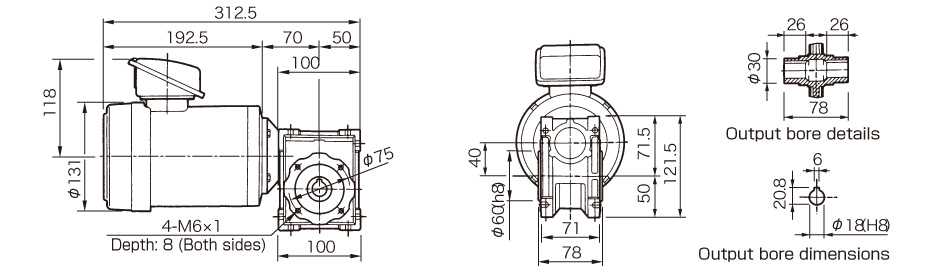
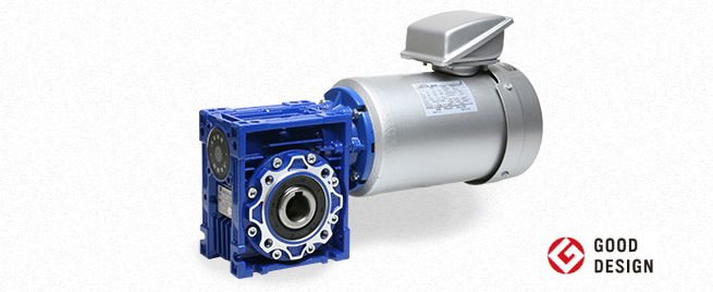
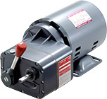
RWM Models

![]()
Dimensions
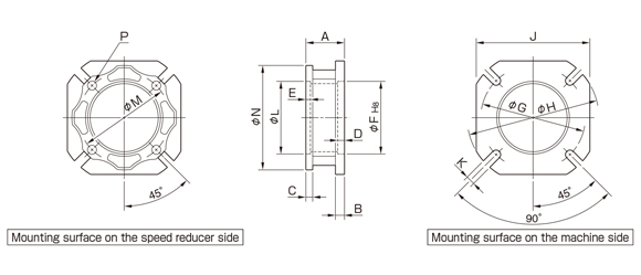
| Model | A | B | C | D | E | F | G | H | J | K | L | M | N | P | Mass[kg] |
|---|---|---|---|---|---|---|---|---|---|---|---|---|---|---|---|
| F-30 | 25.5 | 6 | 6 | 4 | 4 | 50 | 68 | 80 | 70 | 6.5 | 55 | 65 | 75 | 4-⌀6.5 | 0.07 |
| F-40 | 30.5 | 7 | 5 | 4 | 3.5 | 60 | 87 | 110 | 95 | 9 | 60 | 75 | 87 | 4-⌀6.5 | 0.14 |
| F-50 | 46.5 | 9 | 8.5 | 5 | 4 | 70 | 90 | 125 | 110 | 11 | 70 | 85 | 100 | 4-⌀9 | 0.23 |
| F-63 | 29 | 10 | ─ | 6 | 6 | 115 | 150 | 180 | 142 | 11 | 80 | 95 | 110 | 8-⌀9 | 0.29 |
| F-75 | 54 | 13 | ─ | 6 | 7 | 130 | 165 | 200 | 170 | 14 | 95 | 115 | 140 | 8-⌀9 | 0.65 |
*The part can be attached to either the right or left flange part on the speed reducer. Attach it to either side.
*When attaching the output flange F-30, the speed reducer mounting hole and machine mounting hole are 45° out of place with each other.
Dimensions
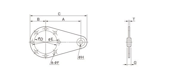
Unit[mm]
| Model | A | B | C | D | E | F | G | H | T | Mass[kg] |
|---|---|---|---|---|---|---|---|---|---|---|
| TA-30 | 85 | 38 | 138 | 55 | 65 | 7 | 14 | (8) | 4 | 0.2 |
| TA-40 | 100 | 44 | 162 | 60 | 75 | 7 | 14 | (10) | 4 | 0.23 |
| TA-50 | 100 | 50 | 168 | 70 | 85 | 9 | 14 | (10) | 4 | 0.3 |
| TA-63 | 150 | 55 | 223 | 80 | 95 | 9 | 14 | (10) | 6 | 0.58 |
| TA-75 | 200 | 70 | 300 | 95 | 115 | 9 | 25 | (20) | 6 | 1.2 |
*The part can be attached to either the right or left flange part on the speed reducer. Attach it to either side.
*TA-40 to -75 models come with a rubber anti-vibration bushing inserted into the ⌀H part.
Dimensions
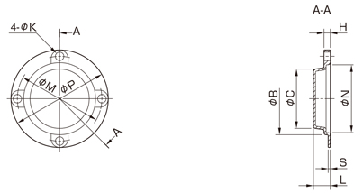
| Model | P | M | K | N | C | B | S | H | L |
|---|---|---|---|---|---|---|---|---|---|
| OC-30 | 75 | 65 | 7 | 56 | 49 | 58 | 1 | 5 | 13 |
| OC-40 | 87 | 75 | 8 | 62 | 51 | 64 | 1 | 5 | 13.5 |
| OC-50 | 100 | 85 | 10 | 72 | 53 | 74 | 1 | 5 | 14 |
| OC-63 | 110 | 95 | 10 | 82 | 61 | 84 | 1 | 5 | 15.5 |
| OC-75 | 140 | 115 | 10 | 97 | 72 | 99 | 1 | 5 | 16.5 |
![]()
![]()
![]()
![]()
![]()
![]()