SFF [DS] Type
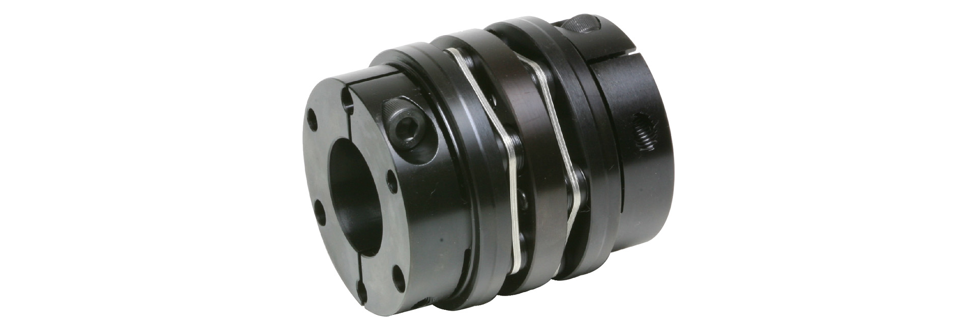
Based on the specifications and dimensions of servo motors used for drive shafts—including permissible torque and compatible shaft diameters—we configure our products to provide the best match for the latest servo motors from various manufacturers. Our lineup includes models featuring a clamp-type design for easy assembly and a wedge-type design for high reliability. The permissible torque significantly exceeds that of conventional products. This is a flexible double-element type.
[Specifications]
| Model | Rated torque [N·m] | Tolerance | Maximum rotational speed [min⁻¹] |
Torsional spring constant [N·m/rad] |
Axial spring constant [N/mm] |
Moment of inertia [kg·m²] |
Mass [kg] | Price [JPY] | ||
|---|---|---|---|---|---|---|---|---|---|---|
| Eccentricity [mm] | Angular offset [°] | Axial [mm] | ||||||||
| SFF-040DS-□B-□B-8N | 8 | 0.10 | 1 (one side) | ±0.4 | 14,000 | 7,500 | 87 | 0.04×10⁻³ | 0.22 | 21,600 |
| SFF-040DS-□B-□B-12N | 12 | 0.10 | 1 (per side) | ±0.4 | 14,000 | 7,500 | 87 | 0.04×10⁻³ | 0.22 | 21,600 |
| SFF-050DS-□B-□B-25N | 25 | 0.20 | 1 (per side) | ±0.6 | 14,000 | 16,000 | 72.5 | 0.13×10⁻³ | 0.46 | 25,410 |
| SFF-060DS-□B-□B-60N | 60 | 0.20 | 1 (per side) | ±0.6 | 14,000 | 52,000 | 199.5 | 0.28×10⁻³ | 0.64 | 29,230 |
| SFF-060DS-□B-□B-80N | 80 | 0.20 | 1 (per side) | ±0.6 | 14,000 | 52,000 | 199.5 | 0.29×10⁻³ | 0.61 | 29,230 |
| SFF-070DS-□B-□B-90N | 90 | 0.25 | 1 (per side) | ±1.0 | 14,000 | 120,000 | 242 | 0.53×10⁻³ | 0.90 | 34,190 |
| SFF-070DS-□B-□B-100N | 100 | 0.25 | 1 (per side) | ±1.0 | 14,000 | 120,000 | 242 | 0.55×10⁻³ | 0.85 | 34,190 |
| SFF-080DS-□B-□B-150N | 150 | 0.32 | 1 (per side) | ±1.0 | 13,000 | 60,000 | 48 | 1.10×10⁻³ | 1.37 | 37,990 |
| SFF-080DS-□B-□B-200N | 200 | 0.31 | 1 (per side) | ±1.0 | 13,000 | 155,000 | 273 | 1.50×10⁻³ | 1.72 | 42,690 |
| SFF-090DS-□B-□B-250N | 250 | 0.32 | 1 (per side) | ±1.2 | 12,000 | 260,000 | 160.5 | 2.03×10⁻³ | 2.02 | 47,400 |
| SFF-090DS-□B-□B-300N | 300 | 0.32 | 1 (per side) | ±1.2 | 12,000 | 260,000 | 160.5 | 2.10×10⁻³ | 1.92 | 47,400 |
| SFF-100DS-□B-□B-450N | 450 | 0.38 | 1 (per side) | ±1.3 | 10,000 | 370,000 | 270 | 4.18×10⁻³ | 3.12 | 52,730 |
| SFF-120DS-□B-□B-600N | 600 | 0.38 | 1 (per side) | ±1.6 | 9000 | 485,000 | 180 | 8.87×10⁻³ | 4.60 | 58,830 |
- The maximum rotational speed does not take dynamic balance into account.
- The torsional spring constant value refers to the value for a single element.
- The moment of inertia and mass are given for the maximum bore diameter.
[Dimensions]

| Model | d1 [mm] |
d2 [mm] |
D [mm] |
L [mm] |
N1 and N2 [mm] |
LF [mm] |
LP [mm] |
S [mm] |
d3 [mm] |
K [mm] |
|---|---|---|---|---|---|---|---|---|---|---|
| SFF-040DS-□B-□B-8N | 8, 9, 9.525 | 8, 9, 9.525, 10, 11, 12, 14, 15, 16 | 38 | 48.8 | 33 | 17.5 | 6 | 3.9 | 17 | 17 |
| SFF-040DS-□B-□B-12N | 10, 11, 12, 14, 15, 16 | 10, 11, 12, 14, 15, 16 | 38 | 48.8 | 33 | 17.5 | 6 | 3.9 | 17 | 17 |
| SFF-050DS-□B-□B-25N | 10, 11, 12, 14, 15, 16, 17, 18, 19 | 10, 11, 12, 14, 15, 16, 17, 18, 19 | 48 | 60.8 | 42 | 21.5 | 7 | 5.4 | 20 | 20 |
| SFF-060DS-□B-□B-60N | 12, 14, 15, 16, 17, 18, 19 | 12, 14, 15, 16, 17, 18, 19, 20, 22 | 58 | 65.8 | 44 | 24 | 7 | 5.4 | 31 | 32 |
| - | 24, 25, 28 | 58 | 65.8 | 48 | 24 | 7 | 5.4 | 31 | 32 | |
| - | 30 | 58 | 65.8 | 52 | 24 | 7 | 5.4 | 31 | 32 | |
| SFF-060DS-□B-□B-80N | 20・22 | 20・22 | 58 | 65.8 | 44 | 24 | 7 | 5.4 | 31 | 32 |
| 24, 25, 28 | 24, 25, 28 | 58 | 65.8 | 48 | 24 | 7 | 5.4 | 31 | 32 | |
| 30 | 30 | 58 | 65.8 | 52 | 24 | 7 | 5.4 | 31 | 32 | |
| SFF-070DS-□B-□B-90N | 18・19 | 18, 19, 20, 22, 24, 25 | 68 | 69.8 | 47 | 25 | 8 | 5.9 | 37 | 38 |
| - | 28, 30, 32, 35 | 68 | 69.8 | 56 | 25 | 8 | 5.9 | 37 | 38 | |
| SFF-070DS-□B-□B-100N | 20, 22, 24, 25 | 20, 22, 24, 25 | 68 | 69.8 | 47 | 25 | 8 | 5.9 | 37 | 38 |
| 28, 30, 32, 35 | 28, 30, 32, 35 | 68 | 69.8 | 56 | 25 | 8 | 5.9 | 37 | 38 | |
| SFF-080DS-□B-□B-150N | 22, 24, 25 | 22, 24, 25 | 78 | 86.6 | 53 | 30 | 10 | 8.3 | 40 | 37 |
| 28, 30, 32, 35 | 28, 30, 32, 35 | 78 | 86.6 | 56 | 30 | 10 | 8.3 | 40 | 37 | |
| SFF-080DS-□B-□B-200N | 22, 24, 25 | 22, 24, 25 | 78 | 85.4 | 53 | 30 | 10 | 7.7 | 40 | 42 |
| 28, 30, 32, 35 | 28, 30, 32, 35 | 78 | 85.4 | 70 | 30 | 10 | 7.7 | 40 | 42 | |
| 38 | 38 | 78 | 85.4 | 74 | 30 | 10 | 7.7 | 40 | 42 | |
| SFF-090DS-□B-□B-250N | 25・28 | 25, 28, 30, 32 | 88 | 86.6 | 66 | 30 | 10 | 8.3 | 50 | 50 |
| - | 35, 38, 40, 42 | 88 | 86.6 | 74 | 30 | 10 | 8.3 | 50 | 50 | |
| SFF-090DS-□B-□B-300N | 30・32 | 30・32 | 88 | 86.6 | 66 | 30 | 10 | 8.3 | 50 | 50 |
| 35, 38, 40, 42 | 35, 38, 40, 42 | 88 | 86.6 | 74 | 30 | 10 | 8.3 | 50 | 50 | |
| SFF-100DS-□B-□B-450N | 32, 35, 38, 40, 42, 45, 48 | 32, 35, 38, 40, 42, 45, 48 | 98 | 112.4 | 84 | 40 | 12 | 10.2 | 52 | 56 |
| SFF-120DS-□B-□B-600N | 32, 35, 38, 40, 42, 45 | 32, 35, 38, 40, 42, 45 | 118 | 112.4 | 84 | 40 | 12 | 10.2 | 72 | 68 |
| 48, 50, 55 | 48, 50, 55 | 118 | 112.4 | 100 | 40 | 12 | 10.2 | 72 | 68 |
- The designation for M1 and M2 clamp bolts consists of the quantity followed by the thread size; the quantity refers to the number of bolts on one side of the hub.
[Standard Hole Diameter]
| Model | Standard hole diameter d1, d2 [mm] | |||||||||||||||||||||||||||
|---|---|---|---|---|---|---|---|---|---|---|---|---|---|---|---|---|---|---|---|---|---|---|---|---|---|---|---|---|
| Nominal | 8 | 9 | 9.525 | 10 | 11 | 12 | 14 | 15 | 16 | 17 | 18 | 19 | 20 | 22 | 24 | 25 | 28 | 30 | 32 | 35 | 38 | 40 | 42 | 45 | 48 | 50 | 55 | |
| SFF-040DS-□B-□B-8N | d1 | ● | ● | ● | ||||||||||||||||||||||||
| d2 | ● | ● | ● | ● | ● | ● | ● | ● | ● | |||||||||||||||||||
| SFF-040DS-□B-□B-12N | d1 | ● | ● | ● | ● | ● | ● | |||||||||||||||||||||
| d2 | ● | ● | ● | ● | ● | ● | ||||||||||||||||||||||
| SFF-050DS-□B-□B-25N | d1 | ● | ● | ● | ● | ● | ● | ● | ● | ● | ||||||||||||||||||
| d2 | ● | ● | ● | ● | ● | ● | ● | ● | ● | |||||||||||||||||||
| SFF-060DS-□B-□B-60N | d1 | ● | ● | ● | ● | ● | ● | ● | ||||||||||||||||||||
| d2 | ● | ● | ● | ● | ● | ● | ● | ● | ● | ● | ● | ● | ● | |||||||||||||||
| SFF-060DS-□B-□B-80N | d1 | ● | ● | ● | ● | ● | ● | |||||||||||||||||||||
| d2 | ● | ● | ● | ● | ● | ● | ||||||||||||||||||||||
| SFF-070DS-□B-□B-90N | d1 | ● | ● | |||||||||||||||||||||||||
| d2 | ● | ● | ● | ● | ● | ● | ● | ● | ● | ● | ||||||||||||||||||
| SFF-070DS-□B-□B-100N | d1 | ● | ● | ● | ● | ● | ● | ● | ● | |||||||||||||||||||
| d2 | ● | ● | ● | ● | ● | ● | ● | ● | ||||||||||||||||||||
| SFF-080DS-□B-□B-150N | d1 | ● | ● | ● | ● | ● | ● | ● | ||||||||||||||||||||
| d2 | ● | ● | ● | ● | ● | ● | ● | |||||||||||||||||||||
| SFF-080DS-□B-□B-200N | d1 | ● | ● | ● | ● | ● | ● | ● | ● | |||||||||||||||||||
| d2 | ● | ● | ● | ● | ● | ● | ● | ● | ||||||||||||||||||||
| SFF-090DS-□B-□B-250N | d1 | ● | ● | |||||||||||||||||||||||||
| d2 | ● | ● | ● | ● | ● | ● | ● | ● | ||||||||||||||||||||
| SFF-090DS-□B-□B-300N | d1 | ● | ● | ● | ● | ● | ● | |||||||||||||||||||||
| d2 | ● | ● | ● | ● | ● | ● | ||||||||||||||||||||||
| SFF-100DS-□B-□B-450N | d1 | ● | ● | ● | ● | ● | ● | ● | ||||||||||||||||||||
| d2 | ● | ● | ● | ● | ● | ● | ● | |||||||||||||||||||||
| SFF-120DS-□B-□B-600N | d1 | ● | ● | ● | ● | ● | ● | ● | ● | ● | ||||||||||||||||||
| d2 | ● | ● | ● | ● | ● | ● | ● | ● | ● | |||||||||||||||||||
- The hole diameters in the fields marked with a ● are supported as standard hole diameters.

[Specifications] Wedge-type fastening
| Model | Rated torque [N·m] | Tolerance | Maximum rotational speed [min⁻¹] |
Torsional spring constant [N·m/rad] |
Axial spring constant [N/mm] |
Moment of inertia [kg·m²] |
Mass [kg] | Price [JPY] | ||
|---|---|---|---|---|---|---|---|---|---|---|
| Eccentricity [mm] | Angular offset [°] | Axial [mm] | ||||||||
| SFF-070DS-□K-□K-100N | 100 | 0.25 | 1 (per side) | ±1.0 | 14,000 | 120,000 | 242 | 0.80×10⁻³ | 1.10 | 42,760 |
| SFF-080DS-□K-□K-150N | 150 | 0.32 | 1 (per side) | ±1.0 | 13,000 | 60,000 | 48 | 1.36×10⁻³ | 1.56 | 47,520 |
| SFF-080DS-□K-□K-200N | 200 | 0.31 | 1 (per side) | ±1.0 | 13,000 | 155,000 | 273 | 1.42×10⁻³ | 1.60 | 50,460 |
| SFF-090DS-□K-□K-300N | 300 | 0.32 | 1 (per side) | ±1.2 | 12,000 | 260,000 | 160.5 | 2.24×10⁻³ | 1.87 | 53,380 |
| SFF-100DS-□K-□K-450N | 450 | 0.38 | 1 (per side) | ±1.3 | 10,000 | 370,000 | 270 | 3.51×10⁻³ | 2.49 | 59,260 |
| SFF-120DS-□K-□K-600N | 600 | 0.38 | 1 (per side) | ±1.6 | 9000 | 485,000 | 180 | 7.17×10⁻³ | 3.29 | 79,660 |
| SFF-140DS-□K-□K-800N | 800 | 0.44 | 1 (per side) | ±2.0 | 8000 | 700,000 | 180 | 14.68×10⁻³ | 6.05 | 102,590 |
| SFF-140DS-□K-□K-1000N | 1000 | 0.44 | 1 (per side) | ±2.0 | 8000 | 700,000 | 180 | 19.11×10⁻³ | 6.39 | 102,590 |
- The maximum rotational speed does not take dynamic balance into account.
- The torsional spring constant value refers to the value for a single element.
- The moment of inertia and mass are given for the maximum bore diameter.
[Dimensions] Wedge-type fastening

| Model | d1 [mm] |
d2 [mm] |
D [mm] |
L [mm] |
N1 and N2 [mm] |
LF [mm] |
LP [mm] |
S [mm] |
C [mm] |
d3 [mm] |
K [mm] |
H [mm] |
M1 Quantity - Nominal |
|---|---|---|---|---|---|---|---|---|---|---|---|---|---|
| SFF-070DS-□K-□K-100N | 18・19 | 18・19 | 68 | 76.8 | 53 | 23.5 | 8 | 5.9 | 5 | 37 | 38 | 3-5.1 | 6-M6 |
| 20, 22, 24, 25 | 20, 22, 24, 25 | 68 | 76.8 | 58 | 23.5 | 8 | 5.9 | 5 | 37 | 38 | 3-5.1 | 6-M6 | |
| 28・30 | 28 and 30 | 68 | 76.8 | 63 | 23.5 | 8 | 5.9 | 5 | 37 | 38 | 3-5.1 | 6-M6 | |
| 32・35 | 32 and 35 | 68 | 76.8 | 68 | 23.5 | 8 | 5.9 | 5 | 37 | 38 | 3-5.1 | 6-M6 | |
| SFF-080DS-□K-□K-150N | 22, 24, 25 | 22, 24, 25 | 78 | 87.6 | 58 | 25.5 | 10 | 8.3 | 5 | 40 | 37 | 4-5.1 | 4-M6 |
| 28・30 | 28 and 30 | 78 | 87.6 | 63 | 25.5 | 10 | 8.3 | 5 | 40 | 37 | 4-5.1 | 4-M6 | |
| 32・35 | 32 and 35 | 78 | 87.6 | 68 | 25.5 | 10 | 8.3 | 5 | 40 | 37 | 4-5.1 | 4-M6 | |
| - | 38 | 78 | 87.6 | 73 | 25.5 | 10 | 8.3 | 5 | 40 | 37 | 4-5.1 | 4-M6 | |
| SFF-080DS-□K-□K-200N | 22, 24, 25 | 22, 24, 25 | 78 | 86.4 | 58 | 25.5 | 10 | 7.7 | 5 | 40 | 42 | 3-5.1 | 6-M6 |
| 28 and 30 | 28 and 30 | 78 | 86.4 | 63 | 25.5 | 10 | 7.7 | 5 | 40 | 42 | 3-5.1 | 6-M6 | |
| 32・35 | 32 and 35 | 78 | 86.4 | 68 | 25.5 | 10 | 7.7 | 5 | 40 | 42 | 3-5.1 | 6-M6 | |
| 38 | 38 | 78 | 86.4 | 73 | 25.5 | 10 | 7.7 | 5 | 40 | 42 | 3-5.1 | 6-M6 | |
| SFF-090DS-□K-□K-300N | 28・30 | 28/30 | 88 | 87.6 | 63 | 25.5 | 10 | 8.3 | 5 | 50 | 50 | 3–6.8 | 6–M6 |
| 32・35 | 32/35 | 88 | 87.6 | 68 | 25.5 | 10 | 8.3 | 5 | 50 | 50 | 3–6.8 | 6-M6 | |
| 38, 40, 42 | 38, 40, 42 | 88 | 87.6 | 73 | 25.5 | 10 | 8.3 | 5 | 50 | 50 | 3–6.8 | 6–M6 | |
| 45 | 45 | 88 | 87.6 | 78 | 25.5 | 10 | 8.3 | 5 | 50 | 50 | 3–6.8 | 6–M6 | |
| 48 | 48 | 88 | 87.6 | 83 | 25.5 | 10 | 8.3 | 5 | 50 | 50 | 3–6.8 | 6-M6 | |
| SFF-100DS-□K-□K-450N | 32・35 | 32・35 | 98 | 97.4 | 68 | 27.5 | 12 | 10.2 | 5 | 52 | 56 | 3–6.8 | 6–M6 |
| 38, 40, 42 | 38, 40, 42 | 98 | 97.4 | 73 | 27.5 | 12 | 10.2 | 5 | 52 | 56 | 3–6.8 | 6–M6 | |
| 45 | 45 | 98 | 97.4 | 78 | 27.5 | 12 | 10.2 | 5 | 52 | 56 | 3–6.8 | 6–M6 | |
| 48/50 | 48/50 | 98 | 97.4 | 83 | 27.5 | 12 | 10.2 | 5 | 52 | 56 | 3–6.8 | 6-M6 | |
| SFF-120DS-□K-□K-600N | 35 | 35 | 118 | 97.4 | 68 | 27.5 | 12 | 10.2 | 5 | 72 | 68 | 3–6.8 | 6-M6 |
| 38, 40, 42 | 38, 40, 42 | 118 | 97.4 | 73 | 27.5 | 12 | 10.2 | 5 | 72 | 68 | 3–6.8 | 6–M6 | |
| 45 | 45 | 118 | 97.4 | 78 | 27.5 | 12 | 10.2 | 5 | 72 | 68 | 3–6.8 | 6-M6 | |
| 48, 50, 52 | 48, 50, 52 | 118 | 97.4 | 83 | 27.5 | 12 | 10.2 | 5 | 72 | 68 | 3–6.8 | 6–M6 | |
| 55 | 55 | 118 | 97.4 | 88 | 27.5 | 12 | 10.2 | 5 | 72 | 68 | 3–6.8 | 6–M6 | |
| 60, 62, 65 | 60, 62, 65 | 118 | 97.4 | 98 | 27.5 | 12 | 10.2 | 5 | 72 | 68 | 3–6.8 | 6–M6 | |
| - | 70 | 118 | 97.4 | 108 | 27.5 | 12 | 10.2 | 5 | 72 | 68 | 3–6.8 | 6-M6 | |
| SFF-140DS-□K-□K-800N | 35・38 | 35・38 | 138 | 120 | 83 | 36.5 | 15 | 10.6 | 5.5 | 80 | 78 | 3–8.6 | 6–M8 |
| 40, 42, 45 | 40, 42, 45 | 138 | 120 | 88 | 36.5 | 15 | 10.6 | 5.5 | 80 | 78 | 3–8.6 | 6-M8 | |
| - | 48, 50, 52 | 138 | 120 | 98 | 36.5 | 15 | 10.6 | 5.5 | 80 | 78 | 3–8.6 | 6–M8 | |
| - | 55–60 | 138 | 120 | 108 | 36.5 | 15 | 10.6 | 5.5 | 80 | 78 | 3–8.6 | 6–M8 | |
| - | 62, 65, 70 | 138 | 120 | 118 | 36.5 | 15 | 10.6 | 5.5 | 80 | 78 | 3–8.6 | 6–M8 | |
| - | 75–80 | 138 | 120 | 128 | 36.5 | 15 | 10.6 | 5.5 | 80 | 78 | 3–8.6 | 6-M8 | |
| SFF-140DS-□K-□K-1000N | 48, 50, 52 | 48, 50, 52 | 138 | 120 | 98 | 36.5 | 15 | 10.6 | 5.5 | 80 | 78 | 3–8.6 | 6–M8 |
| 55–60 | 55/60 | 138 | 120 | 108 | 36.5 | 15 | 10.6 | 5.5 | 80 | 78 | 3–8.6 | 6–M8 | |
| 62, 65, 70 | 62, 65, 70 | 138 | 120 | 118 | 36.5 | 15 | 10.6 | 5.5 | 80 | 78 | 3–8.6 | 6–M8 | |
| 75 | 75–80 | 138 | 120 | 128 | 36.5 | 15 | 10.6 | 5.5 | 80 | 78 | 3–8.6 | 6–M8 |
- The designation for the M1 clamping bolt and the M2 removal screw hole is based on the quantity and thread size. Additionally, the quantities listed for H, M1, and M2 refer to the number on one side of the hub.
[Standard Hole Diameter]
| Model | Standard hole diameter d1, d2 [mm] | ||||||||||||||||||||||||
|---|---|---|---|---|---|---|---|---|---|---|---|---|---|---|---|---|---|---|---|---|---|---|---|---|---|
| Nominal | 18 | 19 | 20 | 22 | 24 | 25 | 28 | 30 | 32 | 35 | 38 | 40 | 42 | 45 | 48 | 50 | 52 | 55 | 60 | 62 | 65 | 70 | 75 | 80 | |
| SFF-070DS-□K-□K-100N | d1 | ● | ● | ● | ● | ● | ● | ● | ● | ● | ● | ||||||||||||||
| d2 | ● | ● | ● | ● | ● | ● | ● | ● | ● | ● | |||||||||||||||
| SFF-080DS-□K-□K-150N | d1 | ● | ● | ● | ● | ● | ● | ● | |||||||||||||||||
| d2 | ● | ● | ● | ● | ● | ● | ● | ● | |||||||||||||||||
| SFF-080DS-□K-□K-200N | d1 | ● | ● | ● | ● | ● | ● | ● | ● | ||||||||||||||||
| d2 | ● | ● | ● | ● | ● | ● | ● | ● | |||||||||||||||||
| SFF-090DS-□K-□K-300N | d1 | ● | ● | ● | ● | ● | ● | ● | ● | ● | |||||||||||||||
| d2 | ● | ● | ● | ● | ● | ● | ● | ● | ● | ||||||||||||||||
| SFF-100DS-□K-□K-450N | d1 | ● | ● | ● | ● | ● | ● | ● | ● | ||||||||||||||||
| d2 | ● | ● | ● | ● | ● | ● | ● | ● | |||||||||||||||||
| SFF-120DS-□K-□K-600N | d1 | ● | ● | ● | ● | ● | ● | ● | ● | ● | ● | ● | ● | ||||||||||||
| d2 | ● | ● | ● | ● | ● | ● | ● | ● | ● | ● | ● | ● | ● | ||||||||||||
| SFF-140DS-□K-□K-800N | d1 | ● | ● | ● | ● | ● | |||||||||||||||||||
| d2 | ● | ● | ● | ● | ● | ● | ● | ● | ● | ● | ● | ● | ● | ● | ● | ||||||||||
| SFF-140DS-□K-□K-1000N | d1 | ● | ● | ● | ● | ● | ● | ● | ● | ● | |||||||||||||||
| d2 | ● | ● | ● | ● | ● | ● | ● | ● | ● | ● | |||||||||||||||
- The hole diameters in the fields marked with a ● are supported as standard hole diameters.