SFU [SS] Type

This is a leaf spring coupling made of steel, featuring a design where the flange—which attaches to the shaft—and the coupling unit can be separated. This not only facilitates high-precision assembly but also allows the drive and driven shafts to be disengaged without moving them during maintenance. It is a single-element coupling with high rigidity.
SFU-□SS(キー)タイプ
SFU-□SS (Key) Type
[Specifications]
| Model | Rated Torque [N·m] | Tolerance | Maximum Rotational Speed [min⁻¹] | Torsional spring constant [N·m/rad] | Axial spring constant [N/mm] | Moment of inertia [kg·m²] | Mass [kg] | ||
|---|---|---|---|---|---|---|---|---|---|
| Eccentricity [mm] | Angular displacement [°] | Axial [mm] | |||||||
| SFU-070SS-100N | 100 | 0.02 | 1 | ±0.5 | 18,000 | 240,000 | 484 | 0.53×10⁻³ | 0.86 |
| SFU-080SS-200N | 200 | 0.02 | 1 | ±0.5 | 17,000 | 310,000 | 546 | 1.26×10⁻³ | 1.52 |
| SFU-090SS-300N | 300 | 0.02 | 1 | ±0.6 | 15,000 | 520,000 | 321 | 2.01×10⁻³ | 1.90 |
| SFU-100SS-450N | 450 | 0.02 | 1 | ±0.65 | 13,000 | 740,000 | 540 | 3.88×10⁻³ | 3.01 |
| SFU-120SS-600N | 600 | 0.02 | 1 | ±0.8 | 11,000 | 970,000 | 360 | 8.17×10⁻³ | 4.31 |
| SFU-140SS-1000N | 1000 | 0.02 | 1 | ±1.0 | 9500 | 1,400,000 | 64 | 18.43×10⁻³ | 6.93 |
- The maximum rotational speed does not take dynamic balance into account.
- The torsional spring constant value refers to the value for a single element.
- The moment of inertia and mass are based on the maximum bore diameter.
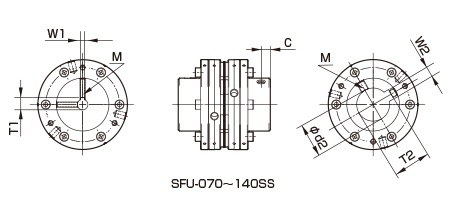
[Dimensions]

| Model | d1・d2 [mm] | D [mm] | N [mm] | L [mm] | LM [mm] | LS [mm] | LF[mm] | S[mm] | F[mm] | d3 [mm] | K[mm] | M1 Quantity - Nominal | M1 Tightening Torque [N·m] | |
|---|---|---|---|---|---|---|---|---|---|---|---|---|---|---|
| Minimum | Max | |||||||||||||
| SFU-070SS-100N | 8 | 25 | 68 | 40 | 69.9 | 28.7 | 23.9 | 23 | 5.9 | 1 | 36 | 38 | 6-M4 | 3.4 |
| SFU-080SS-200N | 11 | 35 | 78 | 54 | 82.7 | 36.5 | 30.7 | 26 | 7.7 | 5 | 38 | 42 | 6-M6 | 14 |
| SFU-090SS-300N | 11 | 38 | 88 | 58 | 90.3 | 37.3 | 30.3 | 30 | 8.3 | 2 | 48 | 50 | 6-M6 | 14 |
| SFU-100SS-450N | 16 | 42 | 98 | 68 | 106.2 | 43.2 | 36.2 | 35 | 10.2 | 0 | 50 | 56 | 6-M8 | 34 |
| SFU-120SS-600N | 19 | 50 | 118 | 78 | 112.2 | 43.2 | 36.2 | 38 | 10.2 | 1 | 66 | 68 | 6-M8 | 34 |
| SFU-140SS-1000N | 22 | 60 | 138 | 88 | 131.6 | 48.6 | 41.6 | 45 | 10.6 | 8 | 76 | 78 | 6-M8 | 34 |
- The designation for an M1 bolt consists of the quantity followed by the thread size, where the quantity refers to the number of flanges on one side.
[Standard Hole Diameter]
| Model | Nominal | Standard Hole Diameter d1・d2 [mm] | |||||||||||||||||||||||||||
|---|---|---|---|---|---|---|---|---|---|---|---|---|---|---|---|---|---|---|---|---|---|---|---|---|---|---|---|---|---|
| 8 | 9 | 10 | 11 | 12 | 14 | 15 | 16 | 17 | 18 | 19 | 20 | 22 | 24 | 25 | 28 | 30 | 32 | 35 | 38 | 40 | 42 | 45 | 48 | 50 | 55 | 56 | 60 | ||
| SFU-070SS-□-□-100N | d1 | ● | ● | ● | ● | ● | ● | ● | ● | ● | ● | ● | ● | ● | ● | ● | |||||||||||||
| d2 | ● | ● | ● | ● | ● | ● | ● | ● | ● | ● | ● | ● | ● | ● | ● | ||||||||||||||
| SFU-080SS-□-□-200N | d1 | ● | ● | ● | ● | ● | ● | ● | ● | ● | ● | ● | ● | ● | ● | ● | ● | ||||||||||||
| d2 | ● | ● | ● | ● | ● | ● | ● | ● | ● | ● | ● | ● | ● | ● | ● | ● | |||||||||||||
| SFU-090SS-□-□-300N | d1 | ● | ● | ● | ● | ● | ● | ● | ● | ● | ● | ● | ● | ● | ● | ● | ● | ● | |||||||||||
| d2 | ● | ● | ● | ● | ● | ● | ● | ● | ● | ● | ● | ● | ● | ● | ● | ● | ● | ||||||||||||
| SFU-100SS-□-□-450N | d1 | ● | ● | ● | ● | ● | ● | ● | ● | ● | ● | ● | ● | ● | ● | ● | |||||||||||||
| d2 | ● | ● | ● | ● | ● | ● | ● | ● | ● | ● | ● | ● | ● | ● | ● | ||||||||||||||
| SFU-120SS-□-□-600N | d1 | ● | ● | ● | ● | ● | ● | ● | ● | ● | ● | ● | ● | ● | ● | ● | |||||||||||||
| d2 | ● | ● | ● | ● | ● | ● | ● | ● | ● | ● | ● | ● | ● | ● | ● | ||||||||||||||
| SFU-140SS-□-□-1000N | d1 | ● | ● | ● | ● | ● | ● | ● | ● | ● | ● | ● | ● | ● | ● | ● | ● | ||||||||||||
| d2 | ● | ● | ● | ● | ● | ● | ● | ● | ● | ● | ● | ● | ● | ● | ● | ● | |||||||||||||
- The hole diameters indicated by the ● symbol are standard hole diameters. For details, please refer to the standard hole machining specifications.

[Standard Hole Machining Specifications]
Unit [mm]
| Compatible with Old JIS (Type 2) Standards | Compliant with New JIS (H9) Standard | Compliant with New JIS (JS 9) Standard | Compliant with New JIS (P9) Standard | ||||||||||||
|---|---|---|---|---|---|---|---|---|---|---|---|---|---|---|---|
| Nominal hole diameter | Hole diameter (d1, d2) |
Keyway width (W1, W2) |
Keyway depth (T1, T2) |
Set screw hole (M) |
Nominal hole diameter | Hole diameter (d1, d2) |
Keyway width (W1, W2) |
Keyway depth (T1, T2) |
Set screw hole (M) |
Nominal hole diameter | Hole diameter (d1, d2) |
Keyway width (W1, W2) |
Keyway depth (T1, T2) |
Set screw hole (M) |
Nominal hole diameter |
| H7, H8 | E9 | +0.3 0 |
- | H7, H8 | H9 | +0.3 0 |
- | H7, H8 | JS9 | +0.3 0 |
- | ||||
| 8 | 8 +0.0220 | - | - | 2–M4 | 8H | 8 + 0.0220 | 3 + 0.0250 | 9.4 | 2-M4 | 8J | 8+0.0220 | 3±0.0125 | 9.4 | 2-M4 | 8P |
| 9 | 9 + 0.0220 | - | - | 2-M4 | 9H | 9 + 0.0220 | 3 + 0.0250 | 10.4 | 2-M4 | 9J | 9+0.0220 | 3±0.0125 | 10.4 | 2-M4 | 9P |
| 10 | 10 + 0.0220 | - | - | 2-M4 | 10H | 10 + 0.0220 | 3 + 0.0250 | 11.4 | 2-M4 | 10J | 10 + 0.0220 | 3±0.0125 | 11.4 | 2-M4 | 10P |
| 11 | 11 + 0.0180 | - | - | 2-M4 | 11H | 11 + 0.0180 | 4 + 0.0300 | 12.8 | 2-M4 | 11J | 11+0.0180 | 4±0.0150 | 12.8 | 2-M4 | 11P |
| 12 | 12+0.0180 | 4 + 0.050 + 0.020 | 13.5 | 2–M4 | 12H | 12 + 0.0180 | 4 + 0.0300 | 13.8 | 2-M4 | 12J | 12+0.0180 | 4±0.0150 | 13.8 | 2-M4 | 12P |
| 14 | 14+0.0180 | 5 + 0.050 + 0.020 | 16.0 | 2–M4 | 14H | 14 + 0.0180 | 5 + 0.0300 | 16.3 | 2-M4 | 14J | 14+0.0180 | 5±0.0150 | 16.3 | 2-M4 | 14P |
| 15 | 15 + 0.0180 | 5 + 0.050 + 0.020 | 17.0 | 2-M4 | 15H | 15 + 0.0180 | 5 + 0.0300 | 17.3 | 2-M4 | 15J | 15+0.0180 | 5±0.0150 | 17.3 | 2-M4 | 15P |
| 16 | 16+0.0180 | 5 + 0.050 + 0.020 | 18.0 | 2–M4 | 16H | 16 + 0.0180 | 5 + 0.0300 | 18.3 | 2-M4 | 16J | 16+0.0180 | 5±0.0150 | 18.3 | 2-M4 | 16P |
| 17 | 17 + 0.0180 | 5 + 0.050 + 0.020 | 19.0 | 2–M4 | 17H | 17+0.0180 | 5 + 0.0300 | 19.3 | 2-M4 | 17J | 17+0.0180 | 5±0.0150 | 19.3 | 2-M4 | 17P |
| 18 | 18 + 0.0180 | 5 + 0.050 + 0.020 | 20.0 | 2-M4 | 18H | 18 + 0.0180 | 6 + 0.0300 | 20.8 | 2-M5 | 18J | 18 + 0.0180 | 6±0.0150 | 20.8 | 2-M5 | 18P |
| 19 | 19 + 0.0210 | 5 + 0.050 + 0.020 | 21.0 | 2–M4 | 19H | 19 + 0.0210 | 6 + 0.0300 | 21.8 | 2-M5 | 19J | 19+0.0210 | 6±0.0150 | 21.8 | 2-M5 | 19P |
| 20 | 20 + 0.0210 | 5 + 0.050 + 0.020 | 22.0 | 2–M4 | 20H | 20 + 0.0210 | 6 + 0.0300 | 22.8 | 2-M5 | 20J | 20 + 0.0210 | 6±0.0150 | 22.8 | 2-M5 | 20P |
| 22 | 22.0210 | 7 + 0.061 + 0.025 | 25.0 | 2–M6 | 22H | 22 + 0.0210 | 6 + 0.0300 | 24.8 | 2-M5 | 22J | 22 + 0.0210 | 6±0.0150 | 24.8 | 2-M5 | 22P |
| 24 | 24 + 0.0210 | 7 + 0.061 + 0.025 | 27.0 | 2–M6 | 24H | 24 + 0.0210 | 8 + 0.0360 | 27.3 | 2-M6 | 24J | 24+0.0210 | 8±0.0180 | 27.3 | 2-M6 | 24P |
| 25 | 25 + 0.0210 | 7 + 0.061 + 0.025 | 28.0 | 2–M6 | 25H | 25 + 0.0210 | 8 + 0.0360 | 28.3 | 2-M6 | 25J | 25+0.0210 | 8±0.0180 | 28.3 | 2-M6 | 25P |
| 28 | 28.0210 | 7 + 0.061 + 0.025 | 31.0 | 2–M6 | 28H | 28 + 0.0210 | 8 + 0.0360 | 31.3 | 2-M6 | 28J | 28+0.0210 | 8±0.0180 | 31.3 | 2-M6 | 28P |
| 30 | 30 + 0.0210 | 7 + 0.061 + 0.025 | 33.0 | 2–M6 | 30H | 30 + 0.0210 | 8 + 0.0360 | 33.3 | 2–M6 | 30J | 30 + 0.0210 | 8±0.0180 | 33.3 | 2-M6 | 30P |
| 32 | 32 + 0.0250 | 10 + 0.061 + 0.025 | 35.5 | 2–M8 | 32H | 32 + 0.0250 | 10 + 0.0360 | 35.3 | 2-M8 | 32J | 32 + 0.0250 | 10±0.0180 | 35.3 | 2-M8 | 32P |
| 35 | 35.000250 | 10 + 0.061 + 0.025 | 38.5 | 2–M8 | 35H | 35 + 0.0250 | 10 + 0.0360 | 38.3 | 2-M8 | 35J | 35+0.0250 | 10±0.0180 | 38.3 | 2-M8 | 35P |
| 38 | 38.00000000000000000000000000000000000000000000000000000000000000 | 10 + 0.061 + 0.025 | 41.5 | 2-M8 | 38H | 38 + 0.0250 | 10 + 0.0360 | 41.3 | 2-M8 | 38J | 38+0.0250 | 10±0.0180 | 41.3 | 2-M8 | 38P |
| 40 | 40+0.0250 | 10 + 0.061 + 0.025 | 43.5 | 2–M8 | 40H | 40 + 0.0250 | 12 + 0.0430 | 43.3 | 2-M8 | 40J | 40 + 0.0250 | 12±0.0215 | 43.3 | 2-M8 | 40P |
| 42 | 42 + 0.0250 | 12 + 0.075 + 0.032 | 45.5 | 2–M8 | 42H | 42 + 0.0250 | 12 + 0.0430 | 45.3 | 2-M8 | 42J | 42 + 0.0250 | 12±0.0215 | 45.3 | 2-M8 | 42P |
| 45 | 45.0250 | 12 + 0.075 + 0.032 | 48.5 | 2–M8 | 45H | 45 + 0.0250 | 14 + 0.0430 | 48.8 | 2-M10 | 45J | 45+0.0250 | 14±0.0215 | 48.8 | 2-M10 | 45P |
| 48 | 48 + 0.0250 | 12 + 0.075 + 0.032 | 51.5 | 2–M8 | 48H | 48 + 0.0250 | 14 + 0.0430 | 51.8 | 2-M10 | 48J | 48 + 0.0250 | 14±0.0215 | 51.8 | 2-M10 | 48P |
| 50 | 50 + 0.0250 | 12 + 0.075 + 0.032 | 53.5 | 2–M8 | 50H | 50 + 0.0250 | 14 + 0.0430 | 53.8 | 2–M10 | 50J | 50 + 0.0250 | 14±0.0215 | 53.8 | 2-M10 | 50P |
| 55 | 55+0.0300 | 15 + 0.075 + 0.032 | 60.0 | 2–M10 | 55H | 55 + 0.0300 | 16 + 0.0430 | 59.3 | 2-M10 | 55J | 55+0.0300 | 16±0.0215 | 59.3 | 2-M10 | 55P |
| 56 | 56+0.0300 | 15 + 0.075 + 0.032 | 61.0 | 2–M10 | 56H | 56 + 0.0300 | 16 + 0.0430 | 60.3 | 2-M10 | 56J | 56+0.0300 | 16±0.0215 | 60.3 | 2-M10 | 56P |
| 60 | 60 + 0.0300 | 15 + 0.075 + 0.032 | 65.0 | 2–M10 | 60H | 60 + 0.0300 | 18 + 0.0430 | 64.4 | 2–M10 | 60J | 60+0.0300 | 18±0.0215 | 64.4 | 2-M10 | 60P |
Unit [mm]
| Compatible with new standard motors | ||||
|---|---|---|---|---|
| Nominal Bore Diameter | Bore Diameter (d1, d2) |
Keyway width (W1, W2) |
Keyway depth (T1, T2) |
Set screw hole (M) |
| G7, F7 | H9 | +0.3 0 |
- | |
| 14N | 14+0.024+0.006 | 5 + 0.0300 | 16.3 | 2–M4 |
| 19N | 19 + 0.028 + 0.007 | 6 + 0.0300 | 21.8 | 2-M5 |
| 24N | 24 + 0.028 + 0.007 | 8 + 0.0360 | 27.3 | 2-M6 |
| 28N | 28 + 0.028 + 0.007 | 8 + 0.0360 | 31.3 | 2–M6 |
| 38N | 38 + 0.050 + 0.025 | 10 + 0.0360 | 41.3 | 2-M8 |
| 42N | 42 + 0.050 + 0.025 | 12 + 0.0430 | 45.3 | 2-M8 |
| 48N | 48 + 0.050 + 0.025 | 14 + 0.0430 | 51.8 | 2-M10 |
| 55N | 55 + 0.060 + 0.030 | 16 + 0.0430 | 59.3 | 2–M10 |
| 60N | 60 + 0.060 + 0.030 | 18 + 0.0430 | 64.4 | 2-M10 |
[Location of the set screw]
| Model | Distance from the end face of the set screw [mm] |
|---|---|
| SFU-070 | 7 |
| SFU-080 | 8 |
| SFU-090 | 9 |
| SFU-100 | 12 |
| SFU-120 | 12 |
| SFU-140 | 15 |
- The set screw and keyway are not located on the same plane. *The set screw is included with the product.
- The positional accuracy of keyway machining is determined by visual inspection. *Please contact us if you require specific positional accuracy for each keyway relative to the hub.