NSS Model
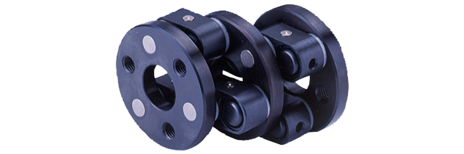
This is an off-center coupling that utilizes the crank motion of the link; power input to one end disc is transmitted to the other end disc via the link and center disc. Because power is transmitted through the crank motion of the link, parallel displacement of the shaft axes is also possible during rotation.
[Specifications]
| Model | Number of links | Eccentricity | Torque | Maximum rotational speed [min⁻¹] | Basic Bearing Load [N] | Pin pitch = Radius of circle [m] | Moment of inertia [kg·m²] | Mass [kg] | Price [JPY] | |||
|---|---|---|---|---|---|---|---|---|---|---|---|---|
| Minimum [mm] S × 0.25 | Maximum [mm] S × 0.95 | Maximum straight length [mm] | Rated [N·m] | Maximum [N·m] | C | R | ||||||
| NSS 7.3.7 | 3×2 | 9 | 34 | 65 | 49 | 137 | 3,000 | 3,870 | 0.024 | 9.03×10⁻⁴ | 1.3 | 96,100 |
| NSS 7.7.9 | 3×2 | 18 | 66 | 128 | 68 | 196 | 2,500 | 3,870 | 0.035 | 2.69×10⁻³ | 1.9 | 106,160 |
| NSS 10.9.12 | 3×2 | 23 | 85 | 165 | 196 | 600 | 2000 | 8920 | 0.045 | 1.15×10⁻² | 4.9 | 141,550 |
| NSS 13.9.14 | 3×2 | 23 | 85 | 165 | 350 | 1060 | 1,800 | 14,120 | 0.050 | 2.80×10⁻² | 10.4 | 172,410 |
| NSS 10/16/16 | 3×2 | 25 | 95 | 183 | 640 | 1850 | 1,500 | 21,570 | 0.057 | 5.80×10⁻² | 15.7 | 234,780 |
| NSS 20.9.20 | 3×2 | 23 | 85 | 165 | 1180 | 3470 | 1,000 | 30,890 | 0.075 | 1.61×10⁻¹ | 27 | 307,070 |
| NSS 20.9.20/4 | 4×2 | 23 | 85 | 165 | 1370 | 4170 | 600 | 30,890 | 0.075 | 1.80×10⁻¹ | 30 | 479,640 |
| NSS 20.9.23/5 | 5×2 | 23 | 85 | 165 | 2060 | 6280 | 500 | 30,890 | 0.090 | 3.08×10⁻¹ | 35 | 617,170 |
| NSS 9/25/20 | 6×2 | 23 | 85 | 165 | 2750 | 8,340 | 460 | 30,890 | 0.100 | 4.48×10⁻¹ | 43 | 718,780 |
| NSS 20.9.33/8 | 8×2 | 23 | 85 | 165 | 5200 | 15,700 | 300 | 30,890 | 0.140 | 1.19 | 59 | 953,080 |
| NSS 20.9.39/10 | 10×2 | 23 | 85 | 165 | 7850 | 23,500 | 250 | 30,890 | 0.170 | 2.25 | 79 | 1,100,150 |
- Any configuration other than 3×2 is made to order.
- The maximum rotational speed does not take dynamic balance into account.
- When selecting the NSS model of the Schmidt coupling, be sure to follow the "Design Considerations" on pages 96–99 and take service life into account.
[Dimensions]
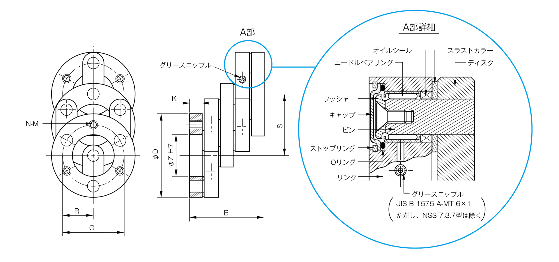
Unit [mm]
| Model | D | B | S | Z | G | N | M | K | CAD File No. |
|---|---|---|---|---|---|---|---|---|---|
| NSS 7.3.7 | 70 | 74 | 36 | 25 | 48 | 3 | M10 | 10 | − |
| NSS 7.7.9 | 92 | 74 | 70 | 45 | 70 | 3 | M10 | 10 | − |
| NSS 10.9.12 | 120 | 101 | 90 | 50 | 90 | 3 | M12 | 15 | − |
| NSS 9/14/13 | 140 | 134 | 90 | 55 | 100 | 3 | M16 | 22 | − |
| NSS 10/16/16 | 160 | 155 | 100 | 60 | 115 | 3 | M16 | 25 | − |
| NSS 9/20/20 | 200 | 196 | 90 | 80 | 150 | 3 | M20 | 30 | − |
| NSS 9/20/20/4 | 200 | 196 | 90 | 80 | 150 | 4 | M20 | 30 | − |
| NSS 9/23/20/5 | 230 | 196 | 90 | 120 | 180 | 5 | M20 | 30 | − |
| NSS 9/25/20/6 | 250 | 196 | 90 | 120 | 200 | 6 | M20 | 30 | − |
| NSS 20.9.33/8 | 330 | 196 | 90 | 210 | 280 | 8 | M20 | 30 | − |
| NSS 20.9.39/10 | 390 | 196 | 90 | 250 | 340 | 10 | M20 | 30 | − |