AL Model
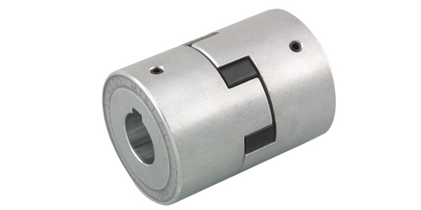
This is a simple jaw coupling consisting of nothing more than a rubber buffer (nitrile rubber) sandwiched between two hubs; the hubs are made of aluminum alloy, making the coupling lightweight. Furthermore, alignment with the shaft is easy—simply place a straight edge against the outer circumference of the hub. Its simple design also makes it an affordable option.
[Specifications]
| Model | Torque | Tolerance | "Maximum rotational speed [min⁻¹]" | "Moment of inertia [kg·m²]" | "Mass [kg]" | "Price of pre-drilled product [JPY]" | |||
|---|---|---|---|---|---|---|---|---|---|
| "Rated [N·m]" | "Maximum [N·m]" | "Eccentricity [mm]" | "Angular Deviation [°]" | "Axial [mm]" | |||||
| AL-035 | 0.5 | 1.5 | 0.1 | 0.5 | 0.3 | 18,000 | 0.38×10⁻⁶ | 0.01 | 1,090 |
| AL-050 | 1.5 | 4.5 | 0.2 | 1 | ±0.5 | 12,000 | 5.10×10⁻⁶ | 0.06 | 1,200 |
| AL-070 | 3 | 9 | 9,000 | 1.79×10⁻⁵ | 0.12 | 1,350 | |||
| AL-075 | 5 | 15 | 7,000 | 5.36×10⁻⁵ | 0.21 | 1,780 | |||
| AL-090 | 8 | 24 | 0.3 | 6,000 | 1.15×10⁻⁴ | 0.31 | 2,190 | ||
| AL-095 | 10 | 30 | 1.40×10⁻⁴ | 0.36 | 2,890 | ||||
| AL-100 | 25 | 75 | ±0.7 | 5,000 | 4.34×10⁻⁴ | 0.78 | 5,630 | ||
| AL-110 | 50 | 150 | 4,000 | 1.43×10⁻³ | 1.56 | 9,770 | |||
- The maximum rotational speed does not take into account dynamic balance or mounting errors.
- The moment of inertia and mass are the values for the bottom hole.
[Dimensions]

Unit [mm]
| Model | d1・d2 | D | L | L1 | L2 | CAD File No. | ||
|---|---|---|---|---|---|---|---|---|
| Pilot hole | Min. | Max | ||||||
| AL-035 | 4 | 4 | 8 | 16.1 | 20.5 | 6.5 | 7.5^*1 | AL0 |
| AL-050 | 5 | 6 | 16 | 27 | 43.2 | 15.5 | 12.2 | AL1 |
| AL-070 | 20 | 35 | 49.2 | 18.5 | AL2 | |||
| AL-075 | 7 | 26 | 45 | 54.4 | 21.0 | 12.4 | AL3 | |
| AL-090 | 9 | 28 | 54 | 55.0 | 13.0 | AL4 | ||
| AL-095 | 55 | 61.0 | 24.0 | AL5 | ||||
| AL-100 | 11 | 36 | 66 | 88.0 | 35.0 | 18.0 | AL6 | |
| AL-110 | 8 | 48 | 85 | 110.0 | 44.0 | 22.0 | AL7 | |
- "Pilot hole" refers to center drilling. The minimum and maximum values for d1 and d2 are based on our standard hole drilling specifications.
- The value in *1 accounts for a 1mm gap around the spider itself.
[Standard Hole Drilling Specifications]
Unit [mm]
| Compliant with JIS B 1301 1959 (Old Standard Type 2) | Compliant with JIS New Standard H9 JIS B 1301 1996 | Compliant with JIS New Standard JS9 JIS B 1301 1996 | Motor Standard: Compliant with JIS C 4210 2001 | ||||||||||||||||
|---|---|---|---|---|---|---|---|---|---|---|---|---|---|---|---|---|---|---|---|
| Nominal hole diameter | Bore Diameter (d1, d2) | Keyway width (W1, W2) | Keyway depth (T1, T2) | Set screw hole (M) | Nominal hole diameter | Hole diameter (d1, d2) | Keyway width (W1, W2) | Keyway depth (T1, T2) | Set screw hole (M) | Nominal hole diameter | Hole diameter (d1, d2) | Keyway width (W1, W2) | Keyway depth (T1, T2) | Set screw hole (M) | Nominal hole diameter | Hole diameter (d1, d2) | Keyway width (W1, W2) | Keyway depth (T1, T2) | Set screw hole (M) |
| Nominal hole diameter | Tolerance H7, H8 | Tolerance E9 | ― | Nominal hole diameter | Tolerance H7 | Tolerance H9 | ― | Nominal hole diameter | Tolerance H7 | Tolerance JS9 | ― | Nominal hole diameter | Tolerance G7, F7 | Tolerance H9 | ― | ||||
| 6 | 6+0.0180 | ― | ― | 2-M4 | ― | ― | ― | ― | ― | ― | ― | ― | ― | ― | ― | ― | ― | ― | ― |
| 7 | 7+0.0220 | ||||||||||||||||||
| 8 | 8 + 0.0220 | ||||||||||||||||||
| 9 | 9 + 0.0220 | ||||||||||||||||||
| 10 | 10 + 0.0220 | ||||||||||||||||||
| 11 | 11 + 0.0180 | ||||||||||||||||||
| 12 | 12 + 0.0180 | 4 + 0.050 + 0.020 | 13.5 + 0.30 | 12H | 12 + 0.0180 | 4 + 0.0300 | 13.8 + 0.30 | 2-M4 | 12J | 12 + 0.0180 | 4±0.0150 | 13.8 + 0.30 | 2-M4 | ||||||
| 14 | 14 + 0.0180 | 5 + 0.050 + 0.020 | 16.0 + 0.30 | 14H | 14 + 0.0180 | 5 + 0.0300 | 16.3 + 0.30 | 14J | 14 + 0.0180 | 5 ± 0.0150 | 16.3 + 0.30 | 14N | 14 + 0.024 + 0.006 | 5 + 0.0300 | 16.3 + 0.30 | 2-M4 | |||
| 15 | 15 + 0.0180 | 17.0 + 0.30 | 15H | 15 + 0.0180 | 17.3 + 0.30 | 15J | 15 + 0.0180 | 17.3 + 0.30 | ― | ― | ― | ― | ― | ||||||
| 16 | 16 + 0.0180 | 18.0 + 0.30 | 16H | 16 + 0.0180 | 18.3 + 0.30 | 16J | 16 + 0.0180 | 18.3 + 0.30 | |||||||||||
| 17 | 17 + 0.0180 | 19.0 + 0.30 | 17H | 17 + 0.0180 | 19.3 + 0.30 | 17J | 17 + 0.0180 | 19.3 + 0.30 | |||||||||||
| 18 | 18 + 0.0180 | 20.0 + 0.30 | 18H | 18 + 0.0180 | 6 + 0.0300 | 20.8 + 0.30 | 2-M5 | 18J | 18 + 0.0180 | 6±0.0150 | 20.8 + 0.30 | 2-M5 | |||||||
| 19 | 19 + 0.0210 | 21.0 + 0.30 | 19H | 19 + 0.0210 | 21.8 + 0.30 | 19J | 19 + 0.0210 | 21.8 + 0.30 | 19N | 19 + 0.028 + 0.007 | 6 + 0.0300 | 21.8 + 0.30 | 2-M5 | ||||||
| 20 | 20 + 0.0210 | 22.0 + 0.30 | 20H | 20 + 0.0210 | 22.8 + 0.30 | 20J | 20 + 0.0210 | 22.8 + 0.30 | ― | ― | ― | ― | ― | ||||||
| 22 | 22 + 0.0210 | 7 + 0.06 1 + 0.025 | 25.0 + 0.30 | 2-M6 | 22H | 22 + 0.0210 | 24.8 + 0.30 | 22J | 22 + 0.0210 | 24.8 + 0.30 | |||||||||
| 24 | 24 + 0.0210 | 27.0 + 0.30 | 24H | 24 + 0.0210 | 8 + 0.0360 | 27.3 + 0.30 | 2-M6 | 24J | 24 + 0.0210 | 8±0.0180 | 27.3 + 0.30 | 2-M6 | 24N | 24 + 0.028 + 0.007 | 8 + 0.0360 | 27.3 + 0.30 | 2-M6 | ||
| 25 | 25 + 0.0210 | 28.0 + 0.30 | 25H | 25 + 0.0210 | 28.3 + 0.30 | 25J | 25 + 0.0210 | 28.3 + 0.30 | ― | ― | ― | ― | ― | ||||||
| 28 | 28 + 0.0210 | 31.0 + 0.30 | 28H | 28 + 0.0210 | 31.3 + 0.30 | 28J | 28 + 0.0210 | 31.3 + 0.30 | 28N | 28 + 0.028 + 0.007 | 8 + 0.0360 | 31.3 + 0.30 | 2-M6 | ||||||
| 30 | 30 + 0.0210 | 33.0 + 0.30 | 30H | 30 + 0.0210 | 33.3 + 0.30 | 30J | 30 + 0.0210 | 33.3 + 0.30 | ― | ― | ― | ― | ― | ||||||
| 32 | 32 + 0.0250 | 10 + 0.06 1 + 0.025 | 35.5 + 0.30 | 2-M8 | 32H | 32 + 0.0250 | 10 + 0.0360 | 35.3 + 0.30 | 2-M8 | 32J | 32 + 0.0250 | 10±0.0180 | 35.3 + 0.30 | 2-M8 | |||||
| 35 | 35 + 0.0250 | 38.5 + 0.30 | 35H | 35 + 0.0250 | 38.3 + 0.30 | 35J | 35 + 0.0250 | 38.3 + 0.30 | |||||||||||
| 38 | 38 + 0.0250 | 41.5 + 0.30 | 38H | 38 + 0.0250 | 41.3 + 0.30 | 38J | 38 + 0.0250 | 41.3 + 0.30 | 38N | 38 + 0.050 + 0.025 | 10 + 0.0360 | 41.3 + 0.30 | 2-M8 | ||||||
| 40 | 40 + 0.0250 | 43.5 + 0.30 | 40H | 40 + 0.0250 | 12 + 0.0430 | 43.3 + 0.30 | 40J | 40 + 0.0250 | 12 ± 0.0215 | 43.3 + 0.30 | ― | ― | ― | ― | ― | ||||
| 42 | 42 + 0.0250 | 12 + 0.075 + 0.032 | 45.5 + 0.30 | 42H | 42 + 0.0250 | 45.3 + 0.30 | 42J | 42 + 0.0250 | 45.3 + 0.30 | 42N | 42 + 0.050 + 0.025 | 12 + 0.0430 | 45.3 + 0.30 | 2-M8 | |||||
| 45 | 45 + 0.0250 | 48.5 + 0.30 | 45H | 45 + 0.0250 | 14 + 0.0430 | 48.8 + 0.30 | 2-M10 | 45J | 45 + 0.0250 | 14±0.0215 | 48.8 + 0.30 | 2-M10 | ― | ― | ― | ― | ― | ||
| 48 | 48 + 0.0250 | 51.5 + 0.30 | 48H | 48 + 0.0250 | 51.8 + 0.30 | 48J | 48 + 0.0250 | 51.8 + 0.30 | 48N | 48 + 0.050 + 0.025 | 14 + 0.0430 | 51.8 + 0.30 | 2-M10 | ||||||
- All specifications for diameters of 11 mm or less are identical to those listed in the "Old JIS Standards" column.
- For AL-035, the tolerance is +0.05+0 regardless of the hole diameter, and the set screw size is M3.
- The set screw and the keyway are not located on the same plane.
- The set screw is included with the product.
- The positional accuracy of keyway machining is checked visually.
- Please contact us if you require positional accuracy for the keyways relative to each hub.
- For standard dimensions of hole patterns other than those listed here, please refer to the technical documentation.

[Location of the set screw]
Unit [mm]
| Model | Distance from end face [mm] |
|---|---|
| AL-035 | 3.5 |
| AL-050 | 7.5 |
| AL-070 | 9 |
| AL-075 | 10 |
| AL-090 | 12 |
| AL-095 | |
| AL-100 | |
| AL-110 | 15 |