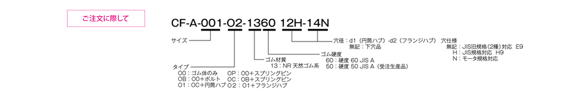
CF-A [O0] Bolt-Mounted Type

Power is transmitted via pre-compressed rubber. It excels at absorbing vibrations and shocks, and also reduces noise from machinery. The elastic rubber component consists of polygonal rubber elements with aluminum inserts at their vertices, each of which is firmly vulcanized and bonded. The O0 type is supplied as the rubber element only.
[Specifications]
| Model | Torque | Tolerance | Maximum Rotational Speed [min⁻¹] |
Dynamic torsional spring constant [N·m/rad] |
Moment of inertia [kg·m²] |
Mass [kg] |
Price [JPY] |
||||
|---|---|---|---|---|---|---|---|---|---|---|---|
| Rated [N·m] |
Maximum [N·m] |
Permissible Variation [N·m/10 Hz] |
Eccentricity [mm] |
Angular Misalignment [°] |
Axial [mm] |
||||||
| CF-A-001-O0-1360 | 10 | 25 | ±4 | 0.5 | 3 | ±2 | 10,000 | 1.47×10² | 2.5×10⁻⁵ | 0.1 | |
| CF-A-002-O0-1360 | 20 | 50 | ±8 | 1 | 3 | ±3 | 8,000 | 2.92×10² | 1.3×10⁻⁴ | 0.2 | |
| CF-A-004-O0-1360 | 40 | 100 | ±16 | 1 | 3 | ±3 | 7,000 | 7.59×10² | 2.8×10⁻⁴ | 0.2 | |
| CF-A-008-O0-1360 | 80 | 200 | ±32 | 1 | 3 | ±4 | 6500 | 1.44×10³ | 7.6×10⁻⁴ | 0.3 | |
| CF-A-012-O0-1360 | 120 | 300 | ±48 | 1 | 2 | ±4 | 6,500 | 4.38×10³ | 8.3×10⁻⁴ | 0.3 | |
| CF-A-016-O0-1360 | 160 | 400 | ±64 | 1.5 | 3 | ±5 | 6000 | 3.28×10³ | 2.5×10⁻³ | 0.7 | |
| CF-A-022-O0-1360 | 220 | 550 | ±88 | 1.5 | 2 | ±5 | 6000 | 8.26×10³ | 2.7×10⁻³ | 0.7 | |
| CF-A-025-O0-1360 | 250 | 630 | ±100 | 1.5 | 3 | ±5 | 5000 | 4.12×10³ | 4.2×10⁻³ | 0.8 | |
| CF-A-028-O0-1360 | 350 | 880 | ±140 | 1.5 | 2 | ±5 | 5,000 | 1.05×10⁴ | 4.6×10⁻³ | 1 | |
| CF-A-030-O0-1360 | 400 | 1000 | ±160 | 1.5 | 3 | ±5 | 4000 | 6.40×10³ | 1.1×10⁻² | 1.5 | |
| CF-A-050-O0-1360 | 600 | 1500 | ±240 | 1.5 | 2 | ±5 | 4000 | 1.48×10⁴ | 1.2×10⁻² | 1.7 | |
| CF-A-080-O0-1360 | 800 | 2000 | ±320 | 1.5 | 2 | ±4 | 4000 | 2.17×10⁴ | 1.5×10⁻² | 2.3 | |
| CF-A-090-O0-1360 | 900 | 2250 | ±360 | 1.5 | 3 | ±5 | 3600 | 1.37×10⁴ | 3.8×10⁻² | 3.2 | |
| CF-A-140-O0-1360 | 1400 | 3500 | ±560 | 1.5 | 2 | ±5 | 3600 | 2.90×10⁴ | 4.2×10⁻² | 3.7 | |
| CF-A-200-O0-1360 | 2000 | 5000 | ±800 | 1.5 | 2 | ±5 | 3200 | 6.08×10⁴ | 7.8×10⁻² | 5.5 | |
| CF-A-250-O0-1360 | 3000 | 8750 | ±1250 | 1.5 | 2 | ±5 | 3000 | 8.28×10⁴ | 0.14 | 7.8 | |
| CF-A-400-O0-1360 | 5000 | 12,500 | ±2000 | 1.5 | 2 | ±5 | 2,800 | 1.25×10⁵ | 0.24 | 11.5 | |
- The maximum rotational speed does not take dynamic balance into account.
- As a general rule, the dynamic torsional spring constant is approximately 1.3 times the static torsional spring constant.
- The values for moment of inertia and mass are for cylindrical hubs and flanged hubs with a through-bore.
[Dimensions]
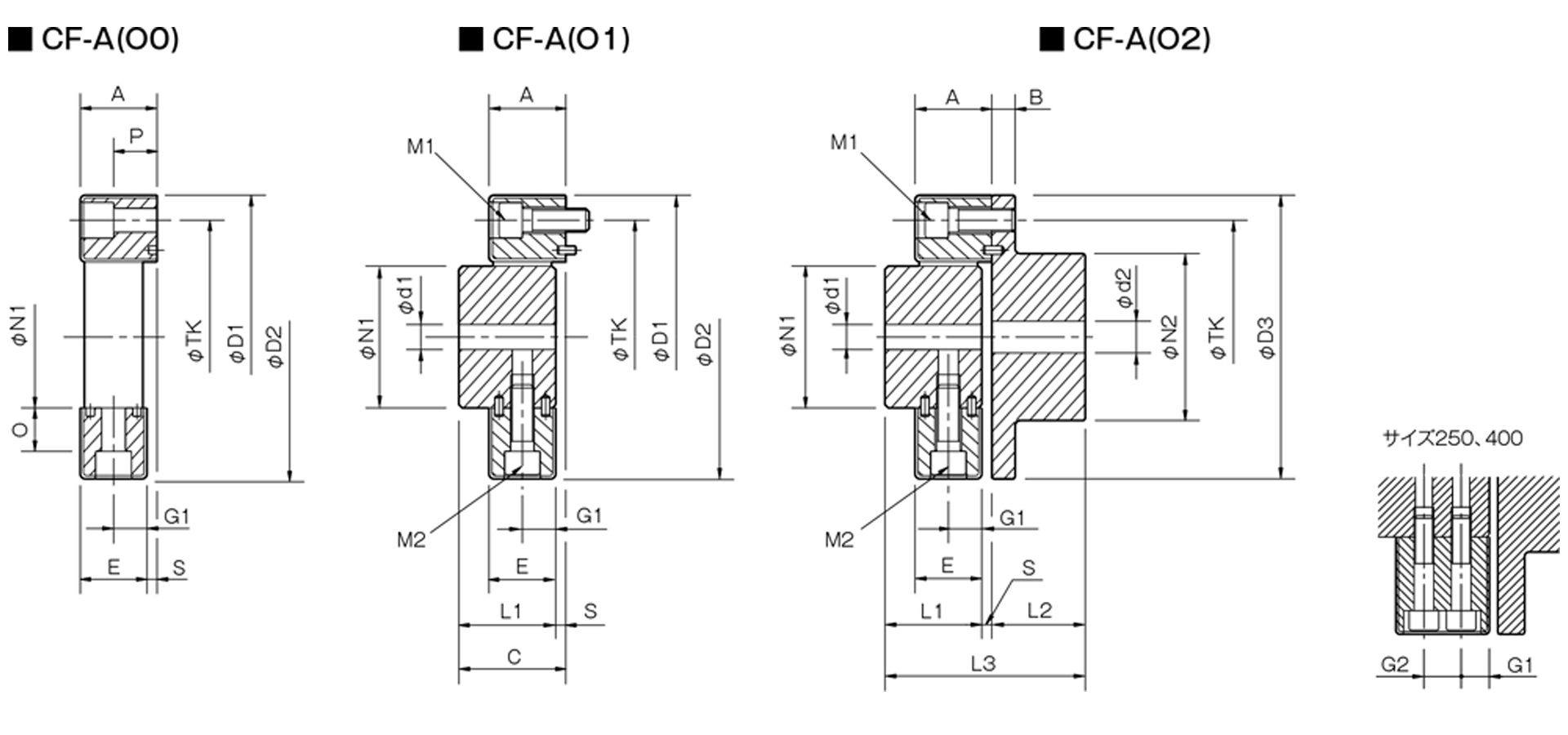
Unit [mm]
| Model | d1 | d2 | D1 | D2 | D3 | N1 | N2 | L1 | L2 | L3 | A | B | C | E | G1 | G2 | O | P | S | TK | M1 | M2 | CAD File No. | ||||
|---|---|---|---|---|---|---|---|---|---|---|---|---|---|---|---|---|---|---|---|---|---|---|---|---|---|---|---|
| Pilot hole | Minimum | Max | Pilot hole | Min | Max | ||||||||||||||||||||||
| CF-A-001 | 8 | 9 | 19 | 8 | 9 | 22 | 57 | 56 | 56 | 30 | 36 | 32 | 24 | 58 | 24 | 7 | 34 | 22 | 11 | - | 5 | 18 | 2 | 44 | 2-M6 | 2-M6 | CF-A11 |
| CF-A-002 | 10 | 11 | 28 | 9 | 10 | 30 | 86 | 85 | 85 | 40 | 45 | 30 | 28 | 62 | 8 | 20 | 10 | 14 | 12 | 4 | 68 | 2-M8 | 2-M8 | CF-A12 | |||
| CF-A-004 | 12 | 14 | 30 | 11 | 12 | 36 | 100 | 97 | 100 | 45 | 55 | 34 | 30 | 68 | 28 | 38 | 24 | 12 | 18.3 | 17 | 80 | 3-M8 | 3-M8 | CF-A13 | |||
| CF-A-008 | 38 | 15 | 16 | 46 | 122 | 120 | 120 | 60 | 70 | 40 | 42 | 86 | 32 | 10 | 44 | 28 | 14 | 20.5 | 20.5 | 100 | 3-M10 | 3-M10 | CF-A14 | ||||
| CF-A-012 | 4-M10 | 4-M10 | CF-A15 | ||||||||||||||||||||||||
| CF-A-016 | 15 | 16 | 48 | 19 | 20 | 56 | 150 | 150 | 150 | 70 | 85 | 52 | 50 | 108 | 42 | 12 | 58 | 36 | 18 | 25 | 23.5 | 6 | 125 | 3-M12 | 3-M12 | CF-A16 | |
| CF-A-022 | 4-M12 | 4-M12 | CF-A17 | ||||||||||||||||||||||||
| CF-A-025 | 55 | 65 | 170 | 170 | 170 | 85 | 100 | 58 | 56 | 120 | 46 | 14 | 64 | 40 | 20 | 26 | 26 | 140 | 3-M14 | 3-M14 | CF-A18 | ||||||
| CF-A-028 | 4-M14 | 4-M14 | CF-A19 | ||||||||||||||||||||||||
| CF-A-030 | 20 | 22 | 65 | 28 | 30 | 80 | 200 | 200 | 200 | 100 | 120 | 68 | 66 | 142 | 58 | 16 | 76 | 50 | 25 | 33 | 34.5 | 8 | 165 | 3-M16 | 3-M16 | CF-A21 | |
| CF-A-050 | 4-M16 | 4-M16 | CF-A22 | ||||||||||||||||||||||||
| CF-A-080 | 205 | 205 | 80 | 150 | 65 | 84 | 61 | 30.5 | 4 | CF-A23 | |||||||||||||||||
| CF-A-090 | 30 | 32 | 85 | 30 | 32 | 95 | 260 | 260 | 260 | 125 | 140 | 84 | 80 | 172 | 70 | 19 | 92 | 62 | 31 | 46 | 45 | 8 | 215 | 3-M20 | 3-M20 | CF-A24 | |
| CF-A-140 | 4-M20 | 4-M20 | CF-A25 | ||||||||||||||||||||||||
| CF-A-200 | 35 | 38 | 105 | 35 | 38 | 110 | 300 | 300 | 300 | 145 | 160 | 94 | 90 | 192 | 80 | 102 | 72 | 36 | 250 | CF-A27 | |||||||
| CF-A-250 | 40 | 42 | 115 | 40 | 42 | 120 | 340 | 340 | 340 | 160 | 180 | 100 | 100 | 208 | 85 | 108 | 77 | 22.5 | 32 | 60 | 60 | 280 | 8-M20 | CF-A26 | |||
| CF-A-400 | 130 | 370 | 370 | 370 | 170 | 200 | 125 | 125 | 260 | 105 | 29 | 135 | 95 | 28.5 | 38 | 70.5 | 67 | 10 | 300 | 4-M24 | CF-A28 | ||||||
- The values in the table above represent the dimensions after the rubber body has been assembled; therefore, the N1, TK, D1, and D2 dimensions prior to assembly differ from those shown in the table.
- The TK dimension refers to the bolt mounting pitch diameter of the flange hub or mating mounting surface.
- The designation for M1 and M2 bolts is based on the quantity and thread size.
- When using hex socket head cap screws with the CF-A-400, you must use the special flat washers included with the rubber body.