CF-A [O2] Bolt-Mounted Type

Power is transmitted via pre-compressed rubber. It excels at absorbing vibrations and shocks, and also reduces noise from machinery. The elastic rubber component consists of a polygonal rubber body with aluminum inserts at its vertices. The coupling set includes a cylindrical hub, a flanged hub, mounting bolts, and spring pins.
[Specifications]
| Model | Torque | Tolerance | Maximum Rotational Speed | Dynamic torsional spring constant | Moment of inertia | Mass [kg] | Price [JPY] | ||||
|---|---|---|---|---|---|---|---|---|---|---|---|
| Standard | Maximum | Permissible Variation | Eccentricity | Angular Deviation | Axial | ||||||
| [N·m] | [N·m] | [N·m/10 Hz] | [mm] | [°] | [mm] | [min⁻¹] | [N·m/rad] | [kg·m²] | |||
| CF-A-001-O2-1360 | 10 | 25 | ±4 | 0.5 | 3 | ±2 | 10,000 | 1.47×10² | 1.3×10⁻⁴ | 0.5 | - |
| CF-A-002-O2-1360 | 20 | 50 | ±8 | 1 | 3 | ±3 | 8,000 | 2.92×10² | 6.3×10⁻⁴ | 1.1 | - |
| CF-A-004-O2-1360 | 40 | 100 | ±16 | 1 | 3 | ±3 | 7,000 | 7.59×10² | 1.3×10⁻³ | 1.5 | - |
| CF-A-008-O2-1360 | 80 | 200 | ±32 | 1 | 3 | ±4 | 6500 | 1.44×10³ | 3.7×10⁻³ | 3.0 | - |
| CF-A-012-O2-1360 | 120 | 300 | ±48 | 1 | 2 | ±4 | 6,500 | 4.38×10³ | 3.9×10⁻³ | 3.1 | - |
| CF-A-016-O2-1360 | 160 | 400 | ±64 | 1.5 | 3 | ±5 | 6000 | 3.28×10³ | 1.1×10⁻² | 5.5 | - |
| CF-A-022-O2-1360 | 220 | 550 | ±88 | 1.5 | 2 | ±5 | 6000 | 8.26×10³ | 1.1×10⁻² | 5.6 | - |
| CF-A-025-O2-1360 | 250 | 630 | ±100 | 1.5 | 3 | ±5 | 5000 | 4.12×10³ | 2.1×10⁻² | 8.5 | - |
| CF-A-028-O2-1360 | 350 | 880 | ±140 | 1.5 | 2 | ±5 | 5000 | 1.05×10⁴ | 2.2×10⁻² | 8.7 | - |
| CF-A-030-O2-1360 | 400 | 1000 | ±160 | 1.5 | 3 | ±5 | 4000 | 6.40×10³ | 4.7×10⁻² | 13.8 | - |
| CF-A-050-O2-1360 | 600 | 1500 | ±240 | 1.5 | 2 | ±5 | 4000 | 1.48×10⁴ | 5.0×10⁻² | 14.2 | - |
| CF-A-080-O2-1360 | 800 | 2000 | ±320 | 1.5 | 2 | ±4 | 4000 | 2.17×10⁴ | 5.4×10⁻² | 15.5 | - |
| CF-A-090-O2-1360 | 900 | 2250 | ±360 | 1.5 | 3 | ±5 | 3600 | 1.37×10⁴ | 0.15 | 26.1 | - |
| CF-A-140-O2-1360 | 1400 | 3500 | ±560 | 1.5 | 2 | ±5 | 3600 | 2.90×10⁴ | 0.16 | 26.8 | - |
| CF-A-200-O2-1360 | 2000 | 5000 | ±800 | 1.5 | 2 | ±5 | 3200 | 6.08×10⁴ | 0.3 | 39.4 | - |
| CF-A-250-O2-1360 | 3000 | 8750 | ±1250 | 1.5 | 2 | ±5 | 3000 | 8.28×10⁴ | 0.5 | 52.3 | - |
| CF-A-400-O2-1360 | 5000 | 12,500 | ±2000 | 1.5 | 2 | ±5 | 2800 | 1.25×10⁵ | 0.97 | 85.0 | - |
- The maximum rotational speed does not take dynamic balance into account.
- As a general rule, the dynamic torsional spring constant is approximately 1.3 times the static torsional spring constant.
- The values for moment of inertia and mass are for cylindrical hubs and flanged hubs with a through-bore.
[Dimensions]
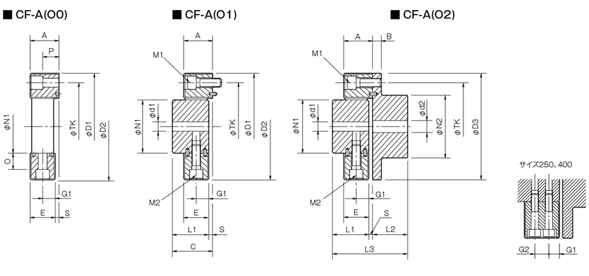
Unit [mm]
| Model | d1 | d2 | D1 | D2 | D3 | N1 | N2 | L1 | L2 | L3 | A | B | C | E | G1 | G2 | O | P | S | TK | M1 | M2 | CAD File No. | ||||
|---|---|---|---|---|---|---|---|---|---|---|---|---|---|---|---|---|---|---|---|---|---|---|---|---|---|---|---|
| Pilot hole | Min. | Max | Pilot hole | Min | Max | ||||||||||||||||||||||
| CF-A-001 | 8 | 9 | 19 | 8 | 9 | 22 | 57 | 56 | 56 | 30 | 36 | 32 | 24 | 58 | 24 | 7 | 34 | 22 | 11 | - | 5 | 18 | 2 | 44 | 2-M6 | 2-M6 | CF-A11 |
| CF-A-002 | 10 | 11 | 28 | 9 | 10 | 30 | 86 | 85 | 85 | 40 | 45 | 30 | 28 | 62 | 24 | 8 | 34 | 20 | 10 | - | 14 | 12 | 4 | 68 | 2-M8 | 2-M8 | CF-A12 |
| CF-A-004 | 12 | 14 | 30 | 11 | 12 | 36 | 100 | 97 | 100 | 45 | 55 | 34 | 30 | 68 | 28 | 8 | 38 | 24 | 12 | - | 18.3 | 17 | 4 | 80 | 3-M8 | 3-M8 | CF-A13 |
| CF-A-008 | 12 | 14 | 38 | 15 | 16 | 46 | 122 | 120 | 120 | 60 | 70 | 40 | 42 | 86 | 32 | 10 | 44 | 28 | 14 | - | 20.5 | 20.5 | 4 | 100 | 3-M10 | 3-M10 | CF-A14 |
| CF-A-012 | 12 | 14 | 38 | 15 | 16 | 46 | 122 | 120 | 120 | 60 | 70 | 40 | 42 | 86 | 32 | 10 | 44 | 28 | 14 | - | 20.5 | 20.5 | 4 | 100 | 4-M10 | 4-M10 | CF-A15 |
| CF-A-016 | 15 | 16 | 48 | 19 | 20 | 56 | 150 | 150 | 150 | 70 | 85 | 52 | 50 | 108 | 42 | 12 | 58 | 36 | 18 | - | 25 | 23.5 | 6 | 125 | 3-M12 | 3-M12 | CF-A16 |
| CF-A-022 | 15 | 16 | 48 | 19 | 20 | 56 | 150 | 150 | 150 | 70 | 85 | 52 | 50 | 108 | 42 | 12 | 58 | 36 | 18 | - | 25 | 23.5 | 6 | 125 | 4-M12 | 4-M12 | CF-A17 |
| CF-A-025 | 15 | 16 | 55 | 19 | 20 | 65 | 170 | 170 | 170 | 85 | 100 | 58 | 56 | 120 | 46 | 14 | 64 | 40 | 20 | - | 26 | 26 | 6 | 140 | 3-M14 | 3-M14 | CF-A18 |
| CF-A-028 | 15 | 16 | 55 | 19 | 20 | 65 | 170 | 170 | 170 | 85 | 100 | 58 | 56 | 120 | 46 | 14 | 64 | 40 | 20 | - | 26 | 26 | 6 | 140 | 4-M14 | 4-M14 | CF-A19 |
| CF-A-030 | 20 | 22 | 65 | 28 | 30 | 80 | 200 | 200 | 200 | 100 | 120 | 68 | 66 | 142 | 58 | 16 | 76 | 50 | 25 | - | 33 | 34.5 | 8 | 165 | 3-M16 | 3-M16 | CF-A21 |
| CF-A-050 | 20 | 22 | 65 | 28 | 30 | 80 | 200 | 200 | 200 | 100 | 120 | 68 | 66 | 142 | 58 | 16 | 76 | 50 | 25 | - | 33 | 34.5 | 8 | 165 | 4-M16 | 4-M16 | CF-A22 |
| CF-A-080 | 20 | 22 | 65 | 28 | 30 | 80 | 205 | 205 | 200 | 100 | 120 | 80 | 66 | 150 | 65 | 16 | 84 | 61 | 30.5 | - | 33 | 34.5 | 4 | 165 | 4-M16 | 4-M16 | CF-A23 |
| CF-A-090 | 30 | 32 | 85 | 30 | 32 | 95 | 260 | 260 | 260 | 125 | 140 | 84 | 80 | 172 | 70 | 19 | 92 | 62 | 31 | - | 46 | 45 | 8 | 215 | 3-M20 | 3-M20 | CF-A24 |
| CF-A-140 | 30 | 32 | 85 | 30 | 32 | 95 | 260 | 260 | 260 | 125 | 140 | 84 | 80 | 172 | 70 | 19 | 92 | 62 | 31 | - | 46 | 45 | 8 | 215 | 4-M20 | 4-M20 | CF-A25 |
| CF-A-200 | 35 | 38 | 105 | 35 | 38 | 110 | 300 | 300 | 300 | 145 | 160 | 94 | 90 | 192 | 80 | 19 | 102 | 72 | 36 | - | 46 | 45 | 8 | 250 | 4-M20 | 4-M20 | CF-A27 |
| CF-A-250 | 40 | 42 | 115 | 40 | 42 | 120 | 340 | 340 | 340 | 160 | 180 | 100 | 100 | 208 | 85 | 19 | 108 | 77 | 22.5 | 32 | 60 | 60 | 8 | 280 | 4-M20 | 8-M20 | CF-A26 |
| CF-A-400 | 40 | 42 | 115 | 40 | 42 | 130 | 370 | 370 | 370 | 170 | 200 | 125 | 125 | 260 | 105 | 29 | 135 | 95 | 28.5 | 38 | 70.5 | 67 | 10 | 300 | 4-M24 | 8-M20 | CF-A28 |
- The pilot hole is a drill hole. The minimum values for d1 and d2 indicate the minimum hole diameters specified in our standard hole machining specifications, while the maximum values indicate the largest hole diameters that can be machined.
- The values in the table above represent the dimensions after the rubber body has been assembled; therefore, the N1, TK, D1, and D2 dimensions prior to assembly differ from those shown in the table.
- The TK dimension refers to the bolt mounting pitch diameter of the flange hub or mating mounting surface.
- The designation for M1 and M2 bolts is based on the quantity and thread size.
- When using hex socket head cap screws with the CF-A-400, you must use the special flat washers included with the rubber body.
[Standard Hole Drilling Specifications]

Unit [mm]
| Compliant with JIS B 1301 1959 (Type 2, Old Standard) | Compliant with JIS New Standard H9 JIS B 1301 1996 | Motor Standard JIS C 4210 2001 | ||||||||||||
|---|---|---|---|---|---|---|---|---|---|---|---|---|---|---|
| Nominal Hole Diameter | Bore diameter (d1, d2) |
Keyway width (W1, W2) |
Keyway depth (T1, T2) |
Set screw hole (M) |
Nominal hole diameter | Hole diameter (d1, d2) |
Keyway width (W1, W2) |
Keyway depth (T1, T2) |
Set screw hole (M) |
Nominal hole diameter | Hole diameter (d1, d2) |
Keyway width (W1, W2) |
Keyway depth (T1, T2) |
Set screw hole (M) |
| Tolerance | H7, H8 | E9 | — | — | Tolerance | H7 | H9 | — | — | Tolerance | G7, F7 | H9 | — | — |
| 9 | 9+0.0220 | — | — | 2-M4 | — | — | — | — | — | — | — | — | — | — |
| 10 | 10+0.0220 | — | — | 2-M4 | — | — | — | — | — | — | — | — | — | — |
| 11 | 11 + 0.0180 | — | — | 2-M4 | — | — | — | — | — | — | — | — | — | — |
| 12 | 12 + 0.0180 | 4 + 0.050 + 0.020 | 13.5 + 0.30 | 2-M4 | 12H | 12 + 0.0180 | 4 + 0.0300 | 13.8 + 0.30 | 2-M4 | — | — | — | — | — |
| 14 | 14 + 0.0180 | 5 + 0.050 + 0.020 | 16.0 + 0.30 | 2-M4 | 14H | 14 + 0.0180 | 5 + 0.0300 | 16.3 + 0.30 | 2-M4 | 14N | 14 + 0.024 + 0.006 | 5 + 0.0300 | 16.3 + 0.30 | 2-M4 |
| 15 | 15 + 0.0180 | 5 + 0.050 + 0.020 | 17.0 + 0.30 | 2-M4 | 15H | 15 + 0.0180 | 5 + 0.0300 | 17.3 + 0.30 | 2-M4 | — | — | — | — | — |
| 16 | 16 + 0.0180 | 5 + 0.050 + 0.020 | 18.0 + 0.30 | 2-M4 | 16H | 16 + 0.0180 | 5 + 0.0300 | 18.3 + 0.30 | 2-M4 | — | — | — | — | — |
| 17 | 17 + 0.0180 | 5 + 0.050 + 0.020 | 19.0 + 0.30 | 2-M4 | 17H | 17+0.0180 | 5 + 0.0300 | 19.3 + 0.30 | 2-M4 | — | — | — | — | — |
| 18 | 18 + 0.0180 | 5 + 0.05 0 + 0.020 | 20.0 + 0.30 | 2-M4 | 18H | 18 + 0.0180 | 6 + 0.0300 | 20.8 + 0.30 | 2-M5 | — | — | — | — | — |
| 19 | 19 + 0.0210 | 5 + 0.050 + 0.020 | 21.0 + 0.30 | 2-M4 | 19H | 19 + 0.0210 | 6 + 0.0300 | 21.8 + 0.30 | 2-M5 | 19N | 19 + 0.028 + 0.007 | 6 + 0.0300 | 21.8 + 0.30 | 2-M5 |
| 20 | 20 + 0.0210 | 5 + 0.05 0 + 0.020 | 22.0 + 0.30 | 2-M4 | 20H | 20 + 0.0210 | 6 + 0.0300 | 22.8 + 0.30 | 2-M5 | — | — | — | — | — |
| 22 | 22 + 0.0210 | 7 + 0.06 1 + 0.025 | 25.0 + 0.30 | 2-M6 | 22H | 22 + 0.0210 | 6 + 0.0300 | 24.8 + 0.30 | 2-M5 | — | — | — | — | — |
| 24 | 24 + 0.0210 | 7 + 0.06 1 + 0.025 | 27.0 + 0.30 | 2-M6 | 24H | 24 + 0.0210 | 8 + 0.0360 | 27.3 + 0.30 | 2-M6 | 24N | 24 + 0.028 + 0.007 | 8 + 0.0360 | 27.3 + 0.30 | 2-M6 |
| 25 | 25 + 0.0210 | 7 + 0.061 + 0.025 | 28.0 + 0.30 | 2-M6 | 25H | 25 + 0.0210 | 8 + 0.0360 | 28.3 + 0.30 | 2-M6 | — | — | — | — | — |
| 28 | 28 + 0.0210 | 7 + 0.061 + 0.025 | 31.0 + 0.30 | 2-M6 | 28H | 28 + 0.0210 | 8 + 0.0360 | 31.3 + 0.30 | 2-M6 | 28N | 28 + 0.02 8 + 0.007 | 8 + 0.0360 | 31.3 + 0.30 | 2-M6 |
| 30 | 30 + 0.0210 | 7 + 0.061 + 0.025 | 33.0 + 0.30 | 2-M6 | 30H | 30 + 0.0210 | 8 + 0.0360 | 33.3 + 0.30 | 2-M6 | — | — | — | — | — |
| 32 | 32 + 0.0250 | 10 + 0.06 1 + 0.025 | 35.5 + 0.30 | 2-M8 | 32H | 32 + 0.0250 | 10 + 0.0360 | 35.3 + 0.30 | 2-M8 | — | — | — | — | — |
| 35 | 35 + 0.0250 | 10 + 0.06 1 + 0.025 | 38.5 + 0.30 | 2-M8 | 35H | 35 + 0.0250 | 10 + 0.0360 | 38.3 + 0.30 | 2-M8 | — | — | — | — | — |
| 38 | 38 + 0.0250 | 10 + 0.06 1 + 0.025 | 41.5 + 0.30 | 2-M8 | 38H | 38 + 0.0250 | 10 + 0.0360 | 41.3 + 0.30 | 2-M8 | 38N | 38 + 0.050 + 0.025 | 10 + 0.0360 | 41.3 + 0.30 | 2-M8 |
| 40 | 40 + 0.0250 | 10 + 0.06 1 + 0.025 | 43.5 + 0.30 | 2-M8 | 40H | 40 + 0.0250 | 12 + 0.0430 | 43.3 + 0.30 | 2-M8 | — | — | — | — | — |
| 42 | 42 + 0.0250 | 12 + 0.075 + 0.032 | 45.5 + 0.30 | 2-M8 | 42H | 42 + 0.0250 | 12 + 0.0430 | 45.3 + 0.30 | 2-M8 | 42N | 42 + 0.050 + 0.025 | 12 + 0.0430 | 45.3 + 0.30 | 2-M8 |
| 45 | 45 + 0.0250 | 12 + 0.075 + 0.032 | 48.5 + 0.30 | 2-M8 | 45H | 45 + 0.0250 | 14 + 0.0430 | 48.8 + 0.30 | 2-M10 | — | — | — | — | — |
| 48 | 48 + 0.0250 | 12 + 0.075 + 0.032 | 51.5 + 0.30 | 2-M8 | 48H | 48 + 0.0250 | 14 + 0.0430 | 51.8 + 0.30 | 2-M10 | 48N | 48 + 0.050 + 0.025 | 14 + 0.0430 | 51.8 + 0.30 | 2-M10 |
| 50 | 50 + 0.0250 | 12 + 0.075 + 0.032 | 53.5 + 0.30 | 2-M8 | 50H | 50 + 0.0250 | 14 + 0.0430 | 53.8 + 0.30 | 2-M10 | — | — | — | — | — |
| 55 | 55 + 0.0300 | 15 + 0.075 + 0.032 | 60.0 + 0.30 | 2-M10 | 55H | 55 + 0.0300 | 16 + 0.0430 | 59.3 + 0.30 | 2-M10 | 55N | 55 + 0.060 + 0.030 | 16 + 0.0430 | 59.3 + 0.30 | 2-M10 |
| 56 | 56 + 0.0300 | 15 + 0.075 + 0.032 | 61.0 + 0.30 | 2-M10 | 56H | 56 + 0.0300 | 16 + 0.0430 | 60.3 + 0.30 | 2-M10 | — | — | — | — | — |
| 60 | 60 + 0.0300 | 15 + 0.075 + 0.032 | 65.0 + 0.30 | 2-M10 | 60H | 60 + 0.0300 | 18 + 0.0430 | 64.4 + 0.30 | 2-M10 | 60N | 60 + 0.060 + 0.030 | 18 + 0.0430 | 64.4 + 0.30 | 2-M10 |
| 63 | 63 + 0.0300 | 18 + 0.075 + 0.032 | 69.0 + 0.30 | 2-M10 | 63H | 63 + 0.0300 | 18 + 0.0430 | 67.4 + 0.30 | 2-M10 | — | — | — | — | — |
| 65 | 65 + 0.0300 | 18 + 0.075 + 0.032 | 71.0 + 0.30 | 2-M10 | 65H | 65 + 0.0300 | 18 + 0.0430 | 69.4 + 0.30 | 2-M10 | 65N | 65 + 0.060 + 0.030 | 18 + 0.0430 | 69.4 + 0.30 | 2-M10 |
- All specifications for diameters of 11 mm or less are identical to those listed in the "Old JIS Standards" section.
- The set screw and the keyway will not be on the same plane.
- The set screw is included with the product.
- The positional accuracy of keyway machining is checked visually.
- Please contact us if you require specific positioning accuracy for the keyways relative to each hub.
- For standard dimensions of hole machining other than those listed here, please refer to the technical documentation.
- We also offer spline machining. Please contact us for more information.

[Location of the set screw (cylindrical hub)]
Unit [mm]
| Cylindrical hub coupling size | Distance from end face [mm] |
|---|---|
| 001 | 6 |
| 002・004 | 6 |
| 008・012 | 7 |
| 016, 022, 025, 028 | 10 |
| 030, 050, 080 | 11 |
| 090, 140 | 13 |
| 200, 250, 400 | 13 |
[Location of the set screw (flange hub)]
Unit [mm]
| Flange hub side coupling size | Distance from end face [mm] |
|---|---|
| 001 | 6 |
| 002・004 | 7 |
| 008・012 | 9 |
| 016, 022, 025, 028 | 10 |
| 030, 050, 080 | 15 |
| 090, 140 | 15 |
| 200, 250, 400 | 16 |