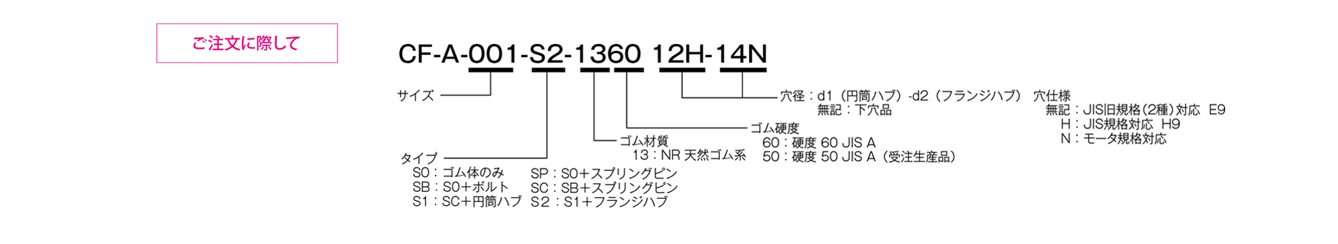
CF-A [SB] Plug-in Mount Type
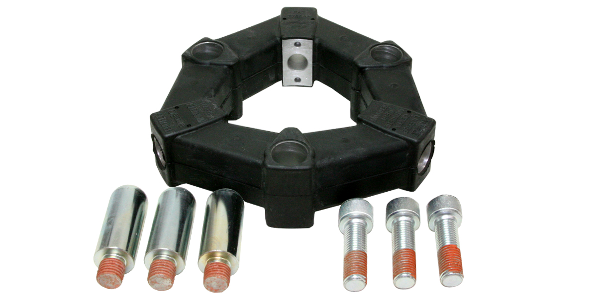
Power is transmitted via pre-compressed rubber. It excels at absorbing vibrations and shocks, and also reduces noise from machinery. The elastic rubber component consists of a polygonal rubber body with aluminum inserts at its vertices. Only the rubber body and mounting bolts are included.
[Specifications]
| Model | Torque | Tolerance | Maximum Rotational Speed | Dynamic torsional spring constant | Moment of inertia | Mass | Price | ||||
|---|---|---|---|---|---|---|---|---|---|---|---|
| Standard | Maximum | Permissible variation | Eccentricity | Angular Deviation | Axial | ||||||
| [N·m] | [N·m] | [N·m/10 Hz] | [mm] | [°] | [mm] | [min⁻¹] | [N·m/rad] | [kg·m²] | [kg] | [JPY] | |
| CF-A-001-SB-1360 | 10 | 25 | ±4 | 0.5 | 3 | ±2 | 10,000 | 1.47×10² | 1.9×10⁻⁵ | 0.1 | |
| CF-A-002-SB-1360 | 20 | 50 | ±8 | 1 | 3 | ±3 | 8,000 | 2.92×10² | 1.2×10⁻⁴ | 0.1 | |
| CF-A-004-SB-1360 | 40 | 100 | ±16 | 1 | 3 | ±3 | 7,000 | 7.59×10² | 2.6×10⁻⁴ | 0.2 | |
| CF-A-008-SB-1360 | 80 | 200 | ±32 | 1 | 3 | ±4 | 6500 | 1.44×10³ | 7.2×10⁻⁴ | 0.3 | |
| CF-A-012-SB-1360 | 120 | 300 | ±48 | 1 | 2 | ±4 | 6,500 | 4.38×10³ | 7.6×10⁻⁴ | 0.3 | |
| CF-A-016-SB-1360 | 160 | 400 | ±64 | 1.5 | 3 | ±5 | 6000 | 3.28×10³ | 2.4×10⁻³ | 0.6 | |
| CF-A-022-SB-1360 | 220 | 550 | ±88 | 1.5 | 2 | ±5 | 6000 | 8.26×10³ | 2.6×10⁻³ | 0.7 | |
| CF-A-025-SB-1360 | 250 | 630 | ±100 | 1.5 | 3 | ±5 | 5000 | 4.12×10³ | 4.0×10⁻³ | 0.8 | |
| CF-A-028-SB-1360 | 350 | 880 | ±140 | 1.5 | 2 | ±5 | 5000 | 1.05×10⁴ | 4.3×10⁻³ | 0.9 | |
| CF-A-030-SB-1360 | 400 | 1000 | ±160 | 1.5 | 3 | ±5 | 4000 | 6.40×10³ | 1.0×10⁻² | 1.4 | |
| CF-A-050-SB-1360 | 600 | 1500 | ±240 | 1.5 | 2 | ±5 | 4000 | 1.48×10⁴ | 1.1×10⁻² | 1.7 | |
| CF-A-080-SB-1360 | 800 | 2000 | ±320 | 1.5 | 2 | ±4 | 4000 | 2.17×10⁴ | 1.5×10⁻² | 2.3 | |
| CF-A-090-SB-1360 | 900 | 2250 | ±360 | 1.5 | 3 | ±5 | 3600 | 1.37×10⁴ | 3.6×10⁻² | 3.1 | |
| CF-A-140-SB-1360 | 1400 | 3500 | ±560 | 1.5 | 2 | ±5 | 3600 | 2.90×10⁴ | 3.8×10⁻² | 3.4 | |
| CF-A-200-SB-1360 | 2000 | 5000 | ±800 | 1.5 | 2 | ±5 | 3200 | 6.08×10⁴ | 7.5×10⁻² | 5.3 | |
| CF-A-250-SB-1360 | 3000 | 8750 | ±1250 | 1.5 | 2 | ±5 | 3000 | 8.28×10⁴ | 0.14 | 7.0 | |
| CF-A-400-SB-1360 | 5000 | 12,500 | ±2000 | 1.5 | 2 | ±5 | 2800 | 1.25×10⁵ | 0.22 | 10.7 | |
- The maximum rotational speed does not take dynamic balance into account.
- As a general rule, the dynamic torsional spring constant is approximately 1.3 times the static torsional spring constant.
- The moment of inertia and mass listed above are assumed to be equivalent to those of the S0 type.
[Dimensions]
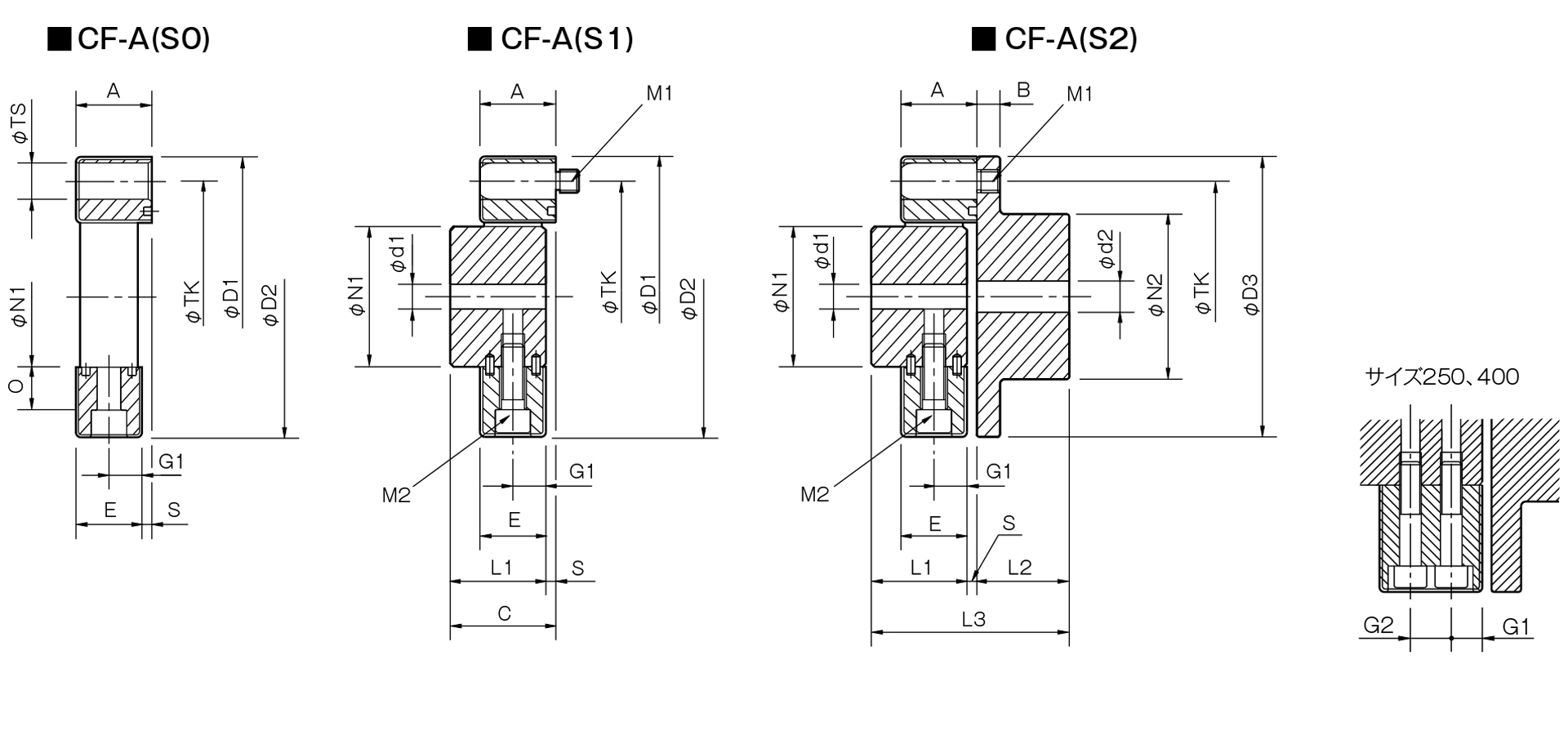
- For the SB type, please refer to [Dimensions] CF-A(S0).
Unit [mm]
| Model | d1 | d2 | D1 | D2 | D3 | N1 | N2 | L1 | L2 | L3 | A | B | C | E | G1 | G2 | O | P | S | TK | M1 | M2 | ||||
|---|---|---|---|---|---|---|---|---|---|---|---|---|---|---|---|---|---|---|---|---|---|---|---|---|---|---|
| Pilot hole | Minimum | Max | Pilot hole | Minimum | Max | |||||||||||||||||||||
| CF-A-001 | 8 | 9 | 19 | 8 | 9 | 22 | 57 | 56 | 56 | 30 | 36 | 32 | 24 | 58 | 24 | 7 | 34 | 22 | 11 | - | 5 | 18 | 2 | 44 | 2-M6 | 2-M6 |
| CF-A-002 | 10 | 11 | 28 | 9 | 10 | 30 | 86 | 85 | 85 | 40 | 45 | 30 | 28 | 62 | 24 | 8 | 34 | 20 | 10 | - | 14 | 12 | 4 | 68 | 2-M8 | 2-M8 |
| CF-A-004 | 12 | 14 | 30 | 11 | 12 | 36 | 100 | 97 | 100 | 45 | 55 | 34 | 30 | 68 | 28 | 8 | 38 | 24 | 12 | - | 18.3 | 17 | 4 | 80 | 3-M8 | 3-M8 |
| CF-A-008 | 12 | 14 | 38 | 15 | 16 | 46 | 122 | 120 | 120 | 60 | 70 | 40 | 42 | 86 | 32 | 10 | 44 | 28 | 14 | - | 20.5 | 20.5 | 4 | 100 | 3-M10 | 3-M10 |
| CF-A-012 | 12 | 14 | 38 | 15 | 16 | 46 | 122 | 120 | 120 | 60 | 70 | 40 | 42 | 86 | 32 | 10 | 44 | 28 | 14 | - | 20.5 | 20.5 | 4 | 100 | 4-M10 | 4-M10 |
| CF-A-016 | 15 | 16 | 48 | 19 | 20 | 56 | 150 | 150 | 150 | 70 | 85 | 52 | 50 | 108 | 42 | 12 | 58 | 36 | 18 | - | 25 | 23.5 | 6 | 125 | 3-M12 | 3-M12 |
| CF-A-022 | 15 | 16 | 48 | 19 | 20 | 56 | 150 | 150 | 150 | 70 | 85 | 52 | 50 | 108 | 42 | 12 | 58 | 36 | 18 | - | 25 | 23.5 | 6 | 125 | 4-M12 | 4-M12 |
| CF-A-025 | 15 | 16 | 55 | 19 | 20 | 65 | 170 | 170 | 170 | 85 | 100 | 58 | 56 | 120 | 46 | 14 | 64 | 40 | 20 | - | 26 | 26 | 6 | 140 | 3-M14 | 3-M14 |
| CF-A-028 | 15 | 16 | 55 | 19 | 20 | 65 | 170 | 170 | 170 | 85 | 100 | 58 | 56 | 120 | 46 | 14 | 64 | 40 | 20 | - | 26 | 26 | 6 | 140 | 4-M14 | 4-M14 |
| CF-A-030 | 20 | 22 | 65 | 28 | 30 | 80 | 200 | 200 | 200 | 100 | 120 | 68 | 66 | 142 | 58 | 16 | 76 | 50 | 25 | - | 33 | 34.5 | 8 | 165 | 3-M16 | 3-M16 |
| CF-A-050 | 20 | 22 | 65 | 28 | 30 | 80 | 200 | 200 | 200 | 100 | 120 | 68 | 66 | 142 | 58 | 16 | 76 | 50 | 25 | - | 33 | 34.5 | 8 | 165 | 4-M16 | 4-M16 |
| CF-A-080 | 20 | 22 | 65 | 28 | 30 | 80 | 205 | 205 | 200 | 100 | 120 | 80 | 66 | 150 | 65 | 16 | 84 | 61 | 30.5 | - | 33 | 34.5 | 4 | 165 | 4-M16 | 4-M16 |
| CF-A-090 | 30 | 32 | 85 | 30 | 32 | 95 | 260 | 260 | 260 | 125 | 140 | 84 | 80 | 172 | 70 | 19 | 92 | 62 | 31 | - | 46 | 45 | 8 | 215 | 3-M20 | 3-M20 |
| CF-A-140 | 30 | 32 | 85 | 30 | 32 | 95 | 260 | 260 | 260 | 125 | 140 | 84 | 80 | 172 | 70 | 19 | 92 | 62 | 31 | - | 46 | 45 | 8 | 215 | 4-M20 | 4-M20 |
| CF-A-200 | 35 | 38 | 105 | 35 | 38 | 110 | 300 | 300 | 300 | 145 | 160 | 94 | 90 | 192 | 80 | 19 | 102 | 72 | 36 | - | 46 | 45 | 8 | 250 | 4-M20 | 4-M20 |
| CF-A-250 | 40 | 42 | 115 | 40 | 42 | 120 | 340 | 340 | 340 | 160 | 180 | 100 | 100 | 208 | 85 | 19 | 108 | 77 | 22.5 | 32 | 60 | 60 | 8 | 280 | 4-M20 | 8-M20 |
| CF-A-400 | 40 | 42 | 115 | 40 | 42 | 130 | 370 | 370 | 370 | 170 | 200 | 125 | 125 | 260 | 105 | 29 | 135 | 95 | 28.5 | 38 | 70.5 | 67 | 10 | 300 | 4-M24 | 8-M20 |
- Bolts are included with the CF-A-S0 (rubber body only).