CF-B [H] Polyester Resin Type

Because the element is made of highly elastic polyester resin, it excels at absorbing vibrations and shocks during power transmission and also reduces noise. The CF-B model features a compact and simple design in which the element is simply sandwiched between two hubs, allowing for smooth power transmission even if the axes of the two shafts are misaligned.
[Specifications]
| Model | Torque | Tolerance |
Maximum Rotational Speed [min⁻¹] |
Static torsional spring constant [N·m/rad] |
Moment of inertia [kg·m²] |
Mass [kg] |
Price for pre-drilled holes\ [JPY] |
|||
|---|---|---|---|---|---|---|---|---|---|---|
| Rated [N·m] |
Maximum [N·m] |
Eccentricity [mm] |
Eccentric angle [°] |
Axial [mm] |
||||||
| CF-B-070-H | 45 | 60 | 0.3 | 0.5 | ±1 | 10,000 | 2.76×10³ | 2.80×10⁻⁴ | 0.7 | |
| CF-B-080-H | 85 | 120 | 0.3 | 0.5 | ±1 | 9000 | 4.15×10³ | 3.39×10⁻⁴ | 0.8 | |
| CF-B-100-H | 170 | 240 | 0.3 | 0.5 | ±1 | 7500 | 9.49×10³ | 1.34×10⁻³ | 2 | |
| CF-B-120-H | 350 | 500 | 0.3 | 0.5 | ±1 | 6000 | 2.03×10⁴ | 3.34×10⁻³ | 3.4 | |
| CF-B-140-H | 560 | 800 | 0.3 | 0.5 | ±1 | 5000 | 3.44×10⁴ | 7.02×10⁻³ | 5.4 | |
| CF-B-165-H | 850 | 1200 | 0.3 | 0.5 | ±1 | 4000 | 5.24×10⁴ | 1.78×10⁻² | 8.7 | |
| CF-B-185-H | 1400 | 2000 | 0.3 | 0.5 | ±1 | 3600 | 2.53×10⁵ | 3.67×10⁻² | 13.8 | |
- The maximum rotational speed does not take dynamic balance into account.
- The values for the static torsional spring constant are given at 20°C.
- The values for moment of inertia, mass, and price are for cylindrical hubs with a through-hole.
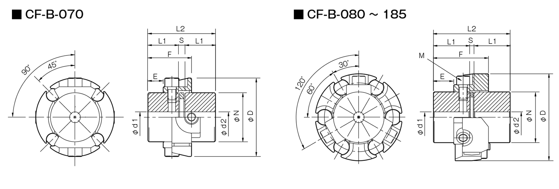
[Dimensions]
| Unit [mm] | |||||||||||
|---|---|---|---|---|---|---|---|---|---|---|---|
| Model | d1・d2 | D | N | L1 | L2 | S | E | F | M | ||
| Pilot hole | Minimum | Max | |||||||||
| CF-B-070 | 9 | 10 | 30 | 72 | 45 | 28 | 62 | 6 | 14 | 40 | 4-M8 |
| CF-B-080 | 12 | 14 | 30 | 76 | 45 | 30 | 66 | 6 | 16 | 42 | 6-M8 |
| CF-B-100 | 12 | 14 | 38 | 98 | 60 | 42 | 90 | 6 | 24 | 64.5 | 6-M10 |
| CF-B-120 | 15 | 16 | 48 | 120 | 70 | 50 | 106 | 6 | 28 | 76 | 6-M12 |
| CF-B-140 | 15 | 16 | 55 | 138 | 85 | 55 | 116 | 6 | 30 | 83 | 6-M14 |
| CF-B-165 | 19 | 20 | 60 | 165 | 100 | 65 | 138 | 8 | 36 | 99 | 6-M16 |
| CF-B-185 | 29 | 30 | 80 | 187 | 115 | 80 | 170 | 10 | 45 | 123 | 6-M20 |
- The pilot hole is a drill hole. The minimum values for d1 and d2 indicate the minimum hole diameters specified in our standard hole machining specifications, while the maximum values indicate the largest hole diameters that can be machined.
- The designation for Bolt M is based on the quantity and thread size.
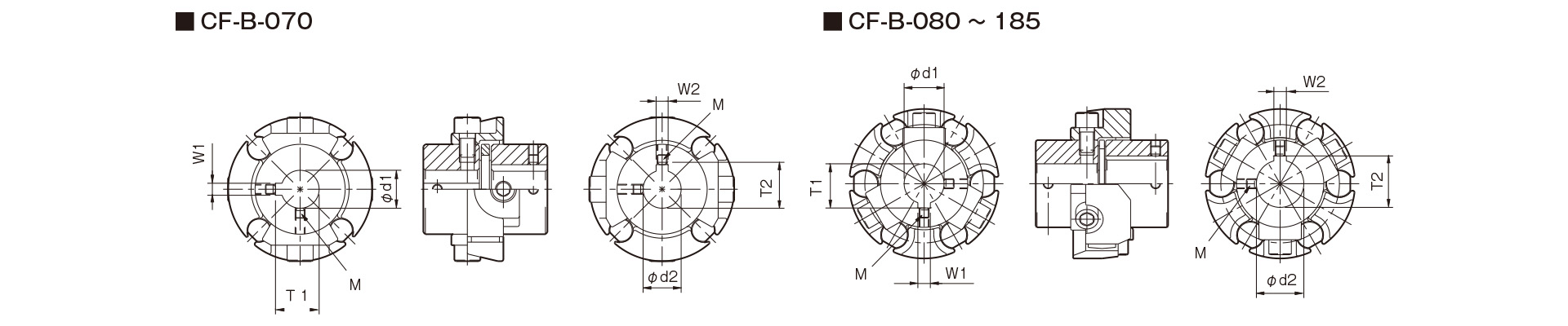
[Standard Hole Drilling Specifications]
| Unit [mm] | ||||||||||||||
|---|---|---|---|---|---|---|---|---|---|---|---|---|---|---|
|
JIS Old Standard Type 2 Compliant with JIS B 1301 1959 |
JIS New Standard H9 Compliant with JIS B 1301 1996 |
Motor Standard Compliant with JIS C 4210 2001 |
||||||||||||
| Nominal Bore Diameter | Bore Diameter (d1, d2) |
Keyway width (W1, W2) |
Keyway depth (T1, T2) |
Set screw hole (M) |
Nominal hole diameter | Hole diameter (d1, d2) |
Keyway width (W1, W2) |
Keyway depth (T1, T2) |
Set screw hole (M) |
Nominal hole diameter | Hole diameter (d1, d2) |
Keyway width (W1, W2) |
Keyway depth (T1, T2) |
Set screw hole (M) |
| Tolerance H7, H8 | Tolerance E9 | +0.30 | ― | Tolerance H7 | Tolerance H9 | ― | Tolerance G7, F7 | Tolerance H9 | ― | |||||
| 10 | 10 +0.022 0 | ― | ― | 2-M4 | ― | ― | ― | ― | ― | ― | ― | ― | ― | ― |
| 11 | 11 +0.018 0 | ― | ― | 2-M4 | ― | ― | ― | ― | ― | ― | ― | ― | ― | ― |
| 12 | 12 +0.018 0 | 4 +0.050 +0.020 | 13.5 +0.30 | 2-M4 | 12H | 12 +0.018 0 | 4 +0.030 0 | 13.8 +0.30 | 2-M4 | ― | ― | ― | ― | ― |
| 14 | 14 +0.018 0 | 5 +0.050 +0.020 | 16.0 +0.30 | 2-M4 | 14H | 14 +0.018 0 | 5 +0.030 0 | 16.3 +0.30 | 2-M4 | 14N | 14 +0.024 +0.006 | 5 +0.030 0 | 16.3 +0.30 | 2-M4 |
| 15 | 15+0.0180 | 5+0.050+0.020 | 17.0+0.30 | 2-M4 | 15H | 15+0.0180 | 5+0.0300 | 17.3+0.30 | 2-M4 | ― | ― | ― | ― | ― |
| 16 | 16+0.0180 | 5+0.050+0.020 | 18.0+0.30 | 2-M4 | 16H | 16+0.0180 | 5+0.0300 | 18.3+0.30 | 2-M4 | ― | ― | ― | ― | ― |
| 17 | 17+0.0180 | 5+0.050+0.020 | 19.0+0.30 | 2-M4 | 17H | 17+0.0180 | 5+0.0300 | 19.3+0.30 | 2-M4 | ― | ― | ― | ― | ― |
| 18 | 18+0.0180 | 5+0.050+0.020 | 20.0+0.30 | 2-M4 | 18H | 18+0.0180 | 6+0.0300 | 20.8+0.30 | 2-M5 | ― | ― | ― | ― | ― |
| 19 | 19+0.0210 | 5+0.050+0.020 | 21.0+0.30 | 2-M4 | 19H | 19+0.0210 | 6+0.0300 | 21.8+0.30 | 2-M5 | 19N | 19+0.028+0.007 | 6+0.0300 | 21.8+0.30 | 2-M5 |
| 20 | 20+0.0210 | 5+0.050+0.020 | 22.0+0.30 | 2-M4 | 20H | 20+0.0210 | 6+0.0300 | 22.8+0.30 | 2-M5 | ― | ― | ― | ― | ― |
| 22 | 22.8+0.0210 | 7+0.061+0.025 | 25.0+0.30 | 2-M6 | 22H | 22+0.0210 | 6+0.0300 | 24.8+0.30 | 2-M5 | ― | ― | ― | ― | ― |
| 24 | 24.8+0.0210 | 7+0.06 1+0.025 | 27.0+0.30 | 2-M6 | 24H | 24+0.0210 | 8+0.0360 | 27.3+0.30 | 2-M6 | 24N | 24+0.028+0.007 | 8+0.0360 | 27.3+0.30 | 2-M6 |
| 25 | 25+0.0210 | 7+0.061+0.025 | 28.0+0.30 | 2-M6 | 25H | 25+0.0210 | 8+0.0360 | 28.3+0.30 | 2-M6 | ― | ― | ― | ― | ― |
| 28 | 28.3+0.0210 | 7+0.061+0.025 | 31.0+0.30 | 2-M6 | 28H | 28+0.0210 | 8+0.0360 | 31.3+0.30 | 2-M6 | 28N | 28+0.028+0.007 | 8+0.0360 | 31.3+0.30 | 2-M6 |
| 30 | 30+0.0210 | 7+0.061+0.025 | 33.0+0.30 | 2-M6 | 30H | 30+0.0210 | 8+0.0360 | 33.3+0.30 | 2-M6 | ― | ― | ― | ― | ― |
| 32 | 32+0.0250 | 10+0.061+0.025 | 35.5+0.30 | 2-M8 | 32H | 32+0.0250 | 10+0.0360 | 35.3+0.30 | 2-M8 | ― | ― | ― | ― | ― |
| 35 | 35+0.0250 | 10+0.061+0.025 | 38.5+0.30 | 2-M8 | 35H | 35+0.0250 | 10+0.0360 | 38.3+0.30 | 2-M8 | ― | ― | ― | ― | ― |
| 38 | 38+0.0250 | 10+0.061+0.025 | 41.5+0.30 | 2-M8 | 38H | 38+0.0250 | 10+0.0360 | 41.3+0.30 | 2-M8 | 38N | 38+0.050+0.025 | 10+0.0360 | 41.3+0.30 | 2-M8 |
| 40 | 40+0.0250 | 10+0.061+0.025 | 43.5+0.30 | 2-M8 | 40H | 40+0.0250 | 12+0.0430 | 43.3+0.30 | 2-M8 | ― | ― | ― | ― | ― |
| 42 | 42+0.0250 | 12+0.075+0.032 | 45.5+0.30 | 2-M8 | 42H | 42+0.0250 | 12+0.0430 | 45.3+0.30 | 2-M8 | 42N | 42+0.050+0.025 | 12+0.0430 | 45.3+0.30 | 2-M8 |
| 45 | 45.3+0.0250 | 12+0.075+0.032 | 48.5+0.30 | 2-M8 | 45H | 45+0.0250 | 14+0.0430 | 48.8+0.30 | 2-M10 | ― | ― | ― | ― | ― |
| 48 | 48.8+0.0250 | 12+0.075+0.032 | 51.5+0.30 | 2-M8 | 48H | 48+0.0250 | 14+0.0430 | 51.8+0.30 | 2-M10 | 48N | 48+0.050+0.025 | 14+0.0430 | 51.8+0.30 | 2-M10 |
| 50 | 50+0.0250 | 12+0.075+0.032 | 53.5+0.30 | 2-M8 | 50H | 50+0.0250 | 14+0.0430 | 53.8+0.30 | 2-M10 | ― | ― | ― | ― | ― |
| 55 | 55+0.0300 | 15+0.075+0.032 | 60.0+0.30 | 2-M10 | 55H | 55+0.0300 | 16+0.0430 | 59.3+0.30 | 2-M10 | 55N | 55+0.060+0.030 | 16+0.0430 | 59.3+0.30 | 2-M10 |
| 56 | 56+0.0300 | 15+0.075+0.032 | 61.0+0.30 | 2-M10 | 56H | 56+0.0300 | 16+0.0430 | 60.3+0.30 | 2-M10 | ― | ― | ― | ― | ― |
| 60 | 60+0.0300 | 15+0.075+0.032 | 65.0+0.30 | 2-M10 | 60H | 60+0.0300 | 18+0.0430 | 64.4+0.30 | 2-M10 | 60N | 60+0.060+0.030 | 18+0.0430 | 64.4+0.30 | 2-M10 |
| 63 | 63+0.0300 | 18+0.075+0.032 | 69.0+0.30 | 2-M10 | 63H | 63+0.0300 | 18+0.0430 | 67.4+0.30 | 2-M10 | ― | ― | ― | ― | ― |
| 65 | 65+0.0300 | 18+0.075+0.032 | 71.0+0.30 | 2-M10 | 65H | 65+0.0300 | 18+0.0430 | 69.4+0.30 | 2-M10 | 65N | 65+0.060+0.030 | 18+0.0430 | 69.4+0.30 | 2-M10 |
- All specifications for diameters of 11 mm or less are identical to those listed in the "Old JIS Standards" column.
- The set screw and the keyway will not be on the same plane.
- The set screw is included with the product.
- The positional accuracy of keyway machining is checked visually.
- Please contact us if you require positional accuracy for the keyway relative to each hub.
- For standard dimensions of hole machining other than those listed here, please refer to the technical documentation.

[Location of the set screw]
| Model | Distance from End Face [mm] |
|---|---|
| CF-B-070 | 7 |
| CF-B-080 | 8 |
| CF-B-100 | 10 |
| CF-B-120 | 10 |
| CF-B-140 | 10 |
| CF-B-165 | 15 |
| CF-B-185 | 15 |