CF-H [O1] Type

Power is transmitted using a polyester resin with elastic properties comparable to those of rubber.In addition to excellent vibration and shock absorption, this coupling offers superior environmental resistance—including heat, cold, and oil resistance—that cannot be achieved with natural rubber. The O1 type includes a resin element, aluminum insert, cylindrical hub, bolts, and spring pins.
[Specifications]
| Model | Torque | Tolerance | Maximum Rotational Speed | Dynamic torsional spring constant | Moment of inertia | Mass | |||
|---|---|---|---|---|---|---|---|---|---|
| Standard | Maximum | Eccentricity | Angular | Axial | |||||
| [N·m] | [N·m] | [mm] | [°] | [mm] | [min⁻¹] | [N·m/rad] | [kg·m²] | [kg] | |
| CF-H-008-O1 | 100 | 200 | 0.3 | 0.5 | ±3 | 6500 | 1.27 × 10⁴ | 1.8 × 10⁻³ | 1.3 |
| CF-H-016-O1 | 200 | 400 | 0.3 | 0.5 | ±3 | 5500 | 2.46 × 10⁴ | 4.9 × 10⁻³ | 2.5 |
| CF-H-030-O1 | 400 | 800 | 0.4 | 0.5 | ±3 | 4000 | 5.91 × 10⁴ | 1.9 × 10⁻² | 6.0 |
| CF-H-040-O1 | 600 | 1200 | 0.4 | 0.5 | ±3 | 4000 | 1.87 × 10⁵ | 1.3 × 10⁻² | 4.4 |
| CF-H-050-O1 | 800 | 1600 | 0.4 | 0.5 | ±3 | 4000 | 1.91 × 10⁵ | 2.3 × 10⁻² | 6.5 |
| CF-H-090-O1 | 950 | 1900 | 0.4 | 0.5 | ±3 | 4000 | 2.69 × 10⁵ | 2.6×10⁻² | 6.9 |
| CF-H-110-O1 | 1100 | 2200 | 0.4 | 0.5 | ±3 | 4000 | 2.79 × 10⁵ | 3.7 × 10⁻² | 9.7 |
| CF-H-160-O1 | 1600 | 3200 | 0.4 | 0.5 | ±3 | 3600 | 5.11 × 10⁵ | 7.0 × 10⁻² | 11.9 |
| CF-H-240-O1 | 2500 | 5000 | 0.4 | 0.5 | ±3 | 3000 | 5.10 × 10⁵ | 0.18 | 20.9 |
- The maximum rotational speed does not take dynamic balance into account.
- Since the dynamic torsional spring characteristics are nonlinear, the dynamic torsional spring constant is applicable at approximately 20% or more of the rated torque.
- As a general rule, the dynamic torsional spring constant is approximately 1.3 times the static torsional spring constant.
- The values for moment of inertia and mass apply to cylindrical hubs and flanged hubs with a bottom bore.
[Dimensions]
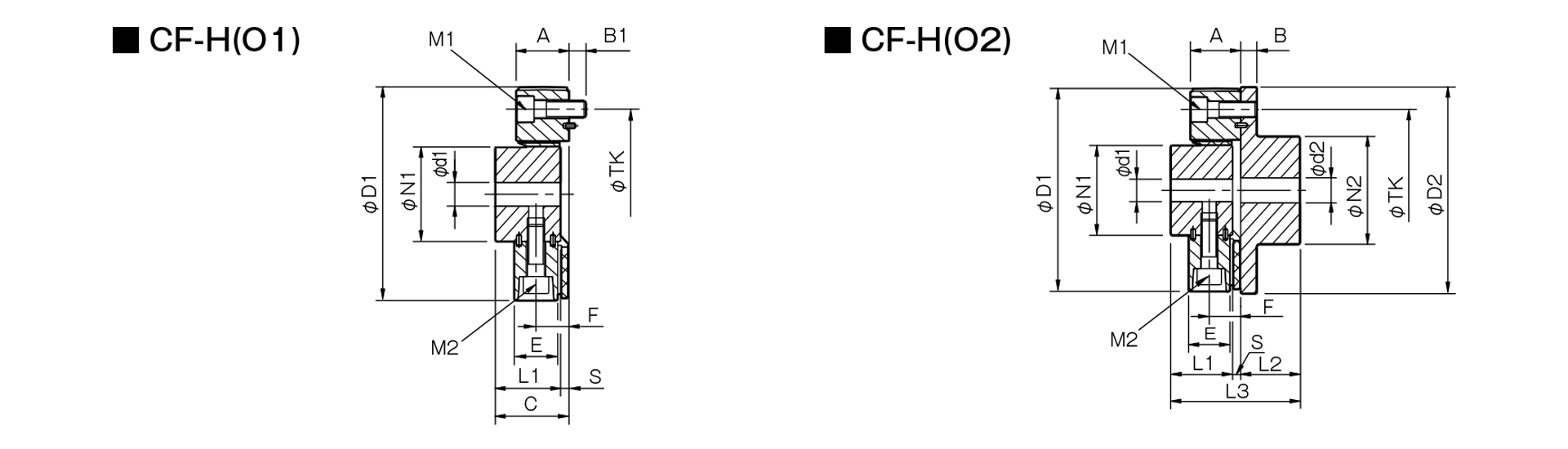
Unit [mm]
| Model | d1 | d2 | D1 | D2 | N1 | N2 | L1 | L2 | L3 | A | B | B1 | C | E | F | S | TK | M1 | M2 | ||||
|---|---|---|---|---|---|---|---|---|---|---|---|---|---|---|---|---|---|---|---|---|---|---|---|
| Pilot hole | Minimum | Max | Pilot hole | Minimum | Max | ||||||||||||||||||
| CF-H-008 | 12 | 14 | 38 | 15 | 16 | 46 | 125 | 120 | 60 | 70 | 40 | 42 | 88 | 32 | 10 | 10 | 46 | 25 | 20 | 6 | 100 | 3-M10 | 3-M10 |
| CF-H-016 | 15 | 16 | 48 | 19 | 20 | 56 | 155 | 150 | 70 | 85 | 52 | 50 | 110 | 41 | 12 | 12 | 60 | 34 | 26 | 8 | 125 | 3-M12 | 3-M12 |
| CF-H-030 | 20 | 22 | 65 | 28 | 30 | 80 | 205 | 200 | 100 | 120 | 68 | 66 | 144 | 56 | 16 | 15 | 78 | 46 | 35 | 10 | 165 | 3-M16 | 3-M16 |
| CF-H-040 | 22 | 24 | 50 | 22 | 24 | 65 | 175 | 180 | 85 | 100 | 58 | 56 | 124 | 50 | 16 | 16 | 68 | 42 | 31 | 10 | 140 | 4-M16 | 4-M16 |
| CF-H-050 | 20 | 22 | 65 | 28 | 30 | 80 | 205 | 200 | 100 | 120 | 68 | 66 | 144 | 56 | 16 | 15 | 78 | 46 | 35 | 10 | 165 | 4-M16 | 4-M16 |
| CF-H-090 | 20 | 22 | 65 | 28 | 30 | 80 | 215 | 200 | 100 | 120 | 68 | 66 | 144 | 56 | 16 | 15 | 78 | 46 | 35 | 10 | 165 | 4-M16 | 4-M16 |
| CF-H-110 | 25 | 28 | 63 | 28 | 30 | 80 | 225 | 230 | 100 | 120 | 68 | 66 | 144 | 56 | 18 | 18 | 78 | 46 | 35 | 10 | 180 | 4-M18 | 4-M18 |
| CF-H-160 | 30 | 32 | 85 | 30 | 32 | 95 | 270 | 260 | 125 | 140 | 84 | 80 | 177 | 59 | 19 | 20 | 97 | 48 | 37 | 13 | 215 | 4-M20 | 4-M20 |
| CF-H-240 | 40 | 42 | 115 | 40 | 42 | 120 | 330 | 320 | 160 | 180 | 100 | 100 | 213 | 65 | 19 | 20 | 113 | 54 | 40 | 13 | 260 | 4-M20 | 4-M20 |
- The pilot hole is a drill hole. The minimum values for d1 and d2 indicate the minimum hole diameters specified in our standard hole machining specifications, while the maximum values indicate the largest hole diameters that can be machined.
- The TK dimension refers to the bolt mounting pitch diameter of the flange hub or mating mounting surface.
[Standard Hole Machining Specifications]

Unit [mm]
| Compatible with Old JIS (Type 2) Standards | Compatible with New JIS Standards | Compatible with New Standard Motors | ||||||||||||
|---|---|---|---|---|---|---|---|---|---|---|---|---|---|---|
| Nominal Bore Diameter | Bore diameter (d1, d2) |
Keyway width (W1, W2) |
Keyway height (T1, T2) |
Set screw hole (M) |
Nominal hole diameter | Hole diameter (d1, d2) |
Keyway width (W1, W2) |
Keyway depth (T1, T2) |
Set screw hole (M) |
Nominal hole diameter | Hole diameter (d1, d2) |
Keyway width (W1, W2) |
Keyway depth (T1, T2) |
Set screw hole (M) |
| Tolerance | H7 | E9 | +0.30 | ― | Tolerance | H7 | H9 | +0.30 | ― | Tolerance | G7, F7 | H9 | +0.30 | ― |
| 14 | 14 +0.0180 0 | 5 +0.050 +0.020 | 16.0 | 2-M4 | 14H | 14 +0.0180 0 | 5 +0.0300 0 | 16.3 | 2-M4 | 14N | 14 +0.024 +0.006 | 5 +0.0300 0 | 16.3 | 2-M4 |
| 15 | 15 +0.0180 0 | 5 +0.050 +0.020 | 17.0 | 2-M4 | 15H | 15 +0.0180 0 | 5 +0.0300 0 | 17.3 | 2-M4 | - | - | - | - | - |
| 16 | 16 +0.0180 0 | 5 +0.050 +0.020 | 18.0 | 2-M4 | 16H | 16 +0.0180 0 | 5 +0.0300 0 | 18.3 | 2-M4 | - | - | - | - | - |
| 17 | 17 +0.0180 0 | 5 +0.050 +0.020 | 19.0 | 2-M4 | 17H | 17 +0.0180 0 | 5 +0.0300 0 | 19.3 | 2-M4 | - | - | - | - | - |
| 18 | 18 +0.0180 0 | 5 +0.050 +0.020 | 20.0 | 2-M4 | 18H | 18 +0.0180 0 | 6 +0.0300 0 | 20.8 | 2-M5 | - | - | - | - | - |
| 19 | 19 +0.0210 0 | 5 +0.050 +0.020 | 21.0 | 2-M4 | 19H | 19 +0.0210 0 | 6 +0.0300 0 | 21.8 | 2-M5 | 19N | 19 +0.028 +0.007 | 6 +0.0300 0 | 21.8 | 2-M5 |
| 20 | 20 +0.0210 0 | 5 +0.050 +0.020 | 22.0 | 2-M4 | 20H | 20 +0.0210 0 | 6 +0.0300 0 | 22.8 | 2-M5 | - | - | - | - | - |
| 22 | 22 +0.0210 0 | 7 +0.061 +0.025 | 25.0 | 2-M6 | 22H | 22 +0.0210 0 | 6 +0.0300 0 | 24.8 | 2-M5 | - | - | - | - | - |
| 24 | 24 +0.0210 0 | 7 +0.061 +0.025 | 27.0 | 2-M6 | 24H | 24 +0.0210 0 | 8 +0.0360 0 | 27.3 | 2-M6 | 24N | 24 +0.028 +0.007 | 8 +0.0360 0 | 27.3 | 2-M6 |
| 25 | 25 +0.0210 0 | 7 +0.061 +0.025 | 28.0 | 2-M6 | 25H | 25 +0.0210 0 | 8 +0.0360 0 | 28.3 | 2-M6 | - | - | - | - | - |
| 28 | 28 +0.0210 0 | 7 +0.061 +0.025 | 31.0 | 2-M6 | 28H | 28 +0.0210 0 | 8 +0.0360 0 | 31.3 | 2-M6 | 28N | 28 +0.028 +0.007 | 8 +0.0360 0 | 31.3 | 2-M6 |
| 30 | 30 +0.0210 0 | 7 +0.061 +0.025 | 33.0 | 2-M6 | 30H | 30 +0.0210 0 | 8 +0.0360 0 | 33.3 | 2-M6 | - | - | - | - | - |
| 32 | 32 +0.0250 0 | 10 +0.061 +0.025 | 35.5 | 2-M8 | 32H | 32 +0.0250 0 | 10 +0.0360 0 | 35.3 | 2-M8 | - | - | - | - | - |
| 35 | 35 +0.0250 0 | 10 +0.061 +0.025 | 38.5 | 2-M8 | 35H | 35 +0.0250 0 | 10 +0.0360 0 | 38.3 | 2-M8 | - | - | - | - | - |
| 38 | 38 +0.0250 0 | 10 +0.061 +0.025 | 41.5 | 2-M8 | 38H | 38 +0.0250 0 | 10 +0.0360 0 | 41.3 | 2-M8 | 38N | 38 +0.050 +0.025 | 10 +0.0360 0 | 41.3 | 2-M8 |
| 40 | 40 +0.0250 0 | 10 +0.061 +0.025 | 43.5 | 2-M8 | 40H | 40 +0.0250 0 | 12 +0.0430 0 | 43.3 | 2-M8 | - | - | - | - | - |
| 42 | 42 +0.0250 0 | 12 +0.075 +0.032 | 45.5 | 2-M8 | 42H | 42 +0.0250 0 | 12 +0.0430 0 | 45.3 | 2-M8 | 42N | 42 +0.050 +0.025 | 12 +0.0430 0 | 45.3 | 2-M8 |
| 45 | 45 +0.0250 0 | 12 +0.075 +0.032 | 48.5 | 2-M8 | 45H | 45 +0.0250 0 | 14 +0.0430 0 | 48.8 | 2-M10 | - | - | - | - | - |
| 48 | 48 +0.0250 0 | 12 +0.075 +0.032 | 51.5 | 2-M8 | 48H | 48 +0.0250 0 | 14 +0.0430 0 | 51.8 | 2-M10 | 48N | 48 +0.050 +0.025 | 14 +0.0430 0 | 51.8 | 2-M10 |
| 50 | 50 +0.0250 0 | 12 +0.075 +0.032 | 53.5 | 2-M8 | 50H | 50 +0.0250 0 | 14 +0.0430 0 | 53.8 | 2-M10 | - | - | - | - | - |
| 55 | 55 +0.0300 0 | 15 +0.075 +0.032 | 60.0 | 2-M10 | 55H | 55 +0.0300 0 | 16 +0.0430 0 | 59.3 | 2-M10 | 55N | 55 +0.060 +0.030 | 16 +0.0430 0 | 59.3 | 2-M10 |
| 56 | 56 +0.0300 0 | 15 +0.075 +0.032 | 61.0 | 2-M10 | 56H | 56 +0.0300 0 | 16 +0.0430 0 | 60.3 | 2-M10 | - | - | - | - | - |
| 60 | 60 +0.0300 0 | 15 +0.075 +0.032 | 65.0 | 2-M10 | 60H | 60 +0.0300 0 | 18 +0.0430 0 | 64.4 | 2-M10 | 60N | 60 +0.060 +0.030 | 18 +0.0430 0 | 64.4 | 2-M10 |
| 63 | 63 +0.0300 0 | 18 +0.075 +0.032 | 69.0 | 2-M10 | 63H | 63 +0.0300 0 | 18 +0.0430 0 | 67.4 | 2-M10 | - | - | - | - | - |
| 65 | 65 +0.0300 0 | 18 +0.075 +0.032 | 71.0 | 2-M10 | 65H | 65 +0.0300 0 | 18 +0.0430 0 | 69.4 | 2-M10 | 65N | 65 +0.060 +0.030 | 18 +0.0430 0 | 69.4 | 2-M10 |

[Location of the set screw (cylindrical hub)]
| Cylindrical Hub Side Coupling Size | Distance from end face [mm] |
|---|---|
| 008 | 7 |
| 016 | 10 |
| 030 | 11 |
| 040 | 10 |
| 050, 090, 110 | 11 |
| 160・240 | 15 |