BXH Model

This is the H-type holding brake from the BXW series, which offers three load torque variations in the same size. It is part of a compact lineup known as the "micro size" among non-excitation holding brakes. Designed to maintain the machine in a stopped state, this brake keeps the equipment stationary.
[Specifications]
| Model | Size | Static friction torque Ts [N·m] | Coil (at 20°C) | Temperature Rating | Lead Wires | Maximum rotational speed [min⁻¹] | Rotating mass moment of inertia J [kg·m²] | Allowable braking work Ebaℓ [J] | Total braking work ET [J] | Armature deceleration time ta [s] | Armature release time tar [s] | Mass [kg] | ||||
|---|---|---|---|---|---|---|---|---|---|---|---|---|---|---|---|---|
| Voltage [V] | Power [W] | Current [A] | Resistance [Ω] | UL Style | Size | |||||||||||
| BXH-06-10 | 06 | 4 | DC24 | 15 | 0.63 | 38.4 | F | UL3398 | AWG 22 | 5000 | 3.25×10⁻⁵ | 700 | 2.0×10⁶ | 0.040 | 0.020 | 0.9 |
| 0.6 | 4 | DC45 | 12 | 0.27 | 169 | F | UL3398 | AWG 22 | 5000 | 3.25×10⁻⁵ | 700 | 2.0×10⁶ | 0.040 | 0.020 | 0.9 | |
| 0.6 | 4 | DC90 | 12 | 0.13 | 677 | F | UL3398 | AWG 22 | 5000 | 3.25×10⁻⁵ | 700 | 2.0×10⁶ | 0.040 | 0.020 | 0.9 | |
| BXH-08-10 | 08 | 8 | DC24 | 22.5 | 0.94 | 25.6 | F | UL3398 | AWG 18 | 5000 | 5.75×10⁻⁵ | 1100 | 3.5×10⁶ | 0.045 | 0.020 | 1.3 |
| 0.08 | 8 | DC45 | 19 | 0.41 | 110 | F | UL3398 | AWG 18 | 5000 | 5.75×10⁻⁵ | 1100 | 3.5×10⁶ | 0.045 | 0.020 | 1.3 | |
| 0.08 | 8 | DC90 | 19 | 0.21 | 440 | F | UL3398 | AWG 18 | 5000 | 5.75×10⁻⁵ | 1100 | 3.5×10⁶ | 0.045 | 0.020 | 1.3 | |
| BXH-10-10 | 10 | 16 | DC24 | 28 | 1.14 | 21.1 | F | UL3398 | AWG 18 | 4000 | 1.30×10⁻⁴ | 1300 | 6.2×10⁶ | 0.070 | 0.025 | 2.3 |
| 10 | 16 | DC45 | 25 | 0.54 | 83 | F | UL3398 | AWG 18 | 4000 | 1.30×10⁻⁴ | 1300 | 6.2×10⁶ | 0.070 | 0.025 | 2.3 | |
| 10 | 16 | DC90 | 25 | 0.27 | 331 | F | UL3398 | AWG 18 | 4000 | 1.30×10⁻⁴ | 1300 | 6.2×10⁶ | 0.070 | 0.025 | 2.3 | |
| BXH-12-10 | 12 | 32 | DC24 | 35 | 1.46 | 16.5 | F | UL3398 | AWG 18 | 3600 | 3.20×10⁻⁴ | 1600 | 9.0×10⁶ | 0.090 | 0.025 | 3.4 |
| 12 | 32 | DC90 | 30 | 0.33 | 271 | F | UL3398 | AWG 18 | 3600 | 3.20×10⁻⁴ | 1600 | 9.0×10⁶ | 0.090 | 0.025 | 3.4 | |
| BXH-16-10 | 16 | 44 | DC24 | 39 | 1.64 | 14.6 | F | UL3398 | AWG 18 | 3000 | 6.93×10⁻⁴ | 2200 | 11.4×10⁶ | 0.125 | 0.030 | 5.4 |
| 16 | 44 | DC90 | 39 | 0.43 | 207 | F | UL3398 | AWG 18 | 3000 | 6.93×10⁻⁴ | 2200 | 11.4×10⁶ | 0.125 | 0.030 | 5.4 | |
- The armature pull-in time and armature release time are values measured during DC-side switching.
- For the armature pull-in and release times during AC-side switching (half-wave rectification), please refer to the operating characteristics page in the catalog.
[Dimensions]
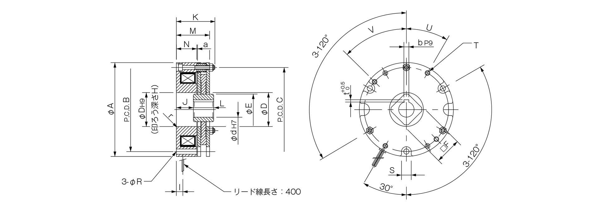
Unit [mm]
| Size | A | B | C | D | r | E | F | H | I | J | K | L | M | N | R | S | T | U | V | a | d | b | t | CAD File No. |
|---|---|---|---|---|---|---|---|---|---|---|---|---|---|---|---|---|---|---|---|---|---|---|---|---|
| 06 | 83 | 73 | 73 | 28 | R1 | 26.5 | 22 | 3 | 10 | 20.5 | 39.5 | 14 | 33.6 | 20 | 4.5 | 9 | 2–M5 | 30° | - | 0.15 | 11 | 4 | 1.5 | BXH1 |
| 08 | 96 | 86 | 86 | 35 | R1 | 32 | 25 | 3 | 12 | 20 | 41 | 17 | 35 | 20.8 | 5.5 | 10.5 | 2–M5 | 30° | - | 0.15 | 14 | 5 | 2 | BXH2 |
| 10 | 116 | 104 | 104 | 42 | R1 | 38 | 30 | 3 | 9.5 | 21 | 47.5 | 25 | 41 | 25.3 | 6.5 | 12.5 | 2–M6 | 30° | - | 0.2 | 19 | 6 | 2.5 | BXH3 |
| 12 | 138 | 124 | 124 | 50 | R1 | 45 | 35 | 4 | 12 | 19 | 49.8 | 30 | 43.5 | 23.3 | 6.5 | 12.5 | 4–M6 | 30° | 45° | 0.2 | 24 | 8 | 3 | BXH4 |
| 16 | 158 | 142 | 143 | 59 | R1 | 55 | 45 | 4 | 14 | 22.5 | 57.5 | 35 | 51 | 27.7 | 9 | 15.5 | 4–M8 | 40° | 40° | 0.25 | 28 | 8 | 3 | BXH5 |
- 3. Unordered List (Asterisk) - 2