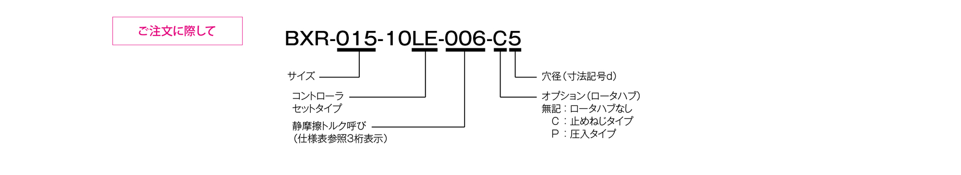
BXR [LE] Model
![三木プーリの無励磁作動形ブレーキ BXR[LE]タイプ 製品画像(無励磁作動 保持用・低発塵仕様・電磁ブレーキ)](/media/cb_of_hld_0le_0l.jpg)
This is a non-excitation-type holding brake designed to be used in conjunction with a dedicated controller that regulates both the electrical energy required to overcome the spring force during the initial phase of brake release and the electrical energy needed to maintain the released state. This design achieves energy savings, low heat generation, and a compact profile.
[Brake System Specifications]
| Model | Size | Static friction torque Ts [N·m] |
Coil (at 20°C) | Temperature Class | Lead Wires | Maximum rotational speed [min⁻¹] |
Rotating mass moment of inertia J [kg·m²] |
Permissible braking work Ebaℓ [J] |
Total Braking Work ET [J] |
Armature hold-in time (24 V DC) ta [s] |
Armature release time (DC 7 V) tar [s] |
Mass [kg] |
||||||||
|---|---|---|---|---|---|---|---|---|---|---|---|---|---|---|---|---|---|---|---|---|
| Over-excitation output | Steady-state excitation output | |||||||||||||||||||
| Voltage [V] |
Power [W] |
Current [A] |
Resistance [Ω] |
Voltage [V] |
Power [W] |
Current [A] |
Resistance [Ω] |
UL Style | Size | |||||||||||
| BXR-015-10LE | 015 | 0.06 | 24 | 16.5 | 0.688 | 35 | 7 | 1.4 | 0.200 | 35 | F | UL3398 | AWG 26 | 6000 | 3.24×10⁻⁸ | 5 | 1000 | 0.020 | 0.020 | 0.03 |
| BXR-020-10LE | 020 | 0.14 | 24 | 16.5 | 0.688 | 35 | 7 | 1.4 | 0.200 | 35 | F | UL3398 | AWG 26 | 6000 | 7.01×10⁻⁸ | 15 | 3000 | 0.035 | 0.020 | 0.06 |
| BXR-025-10LE | 025 | 0.32 | 24 | 16.5 | 0.688 | 35 | 7 | 1.4 | 0.200 | 35 | F | UL3398 | AWG 26 | 6000 | 1.96×10⁻⁷ | 15 | 3000 | 0.035 | 0.020 | 0.08 |
| BXR-035-10LE | 035 | 0.62 | 24 | 16.5 | 0.688 | 35 | 7 | 1.4 | 0.200 | 35 | F | UL3398 | AWG 26 | 6000 | 6.20×10⁻⁷ | 87 | 17,000 | 0.050 | 0.020 | 0.12 |
| BXR-040-10LE | 040 | 1.32 | 24 | 16.5 | 0.688 | 35 | 7 | 1.4 | 0.200 | 35 | F | UL3398 | AWG 26 | 6000 | 1.29×10⁻⁶ | 87 | 17,000 | 0.060 | 0.020 | 0.16 |
| BXR-050-10LE | 050 | 3.20 | 24 | 16.5 | 0.688 | 35 | 7 | 1.4 | 0.200 | 35 | F | UL3398 | AWG 26 | 6000 | 2.57×10⁻⁶ | 200 | 40,000 | 0.060 | 0.020 | 0.40 |
[Brake Assembly Dimensions]
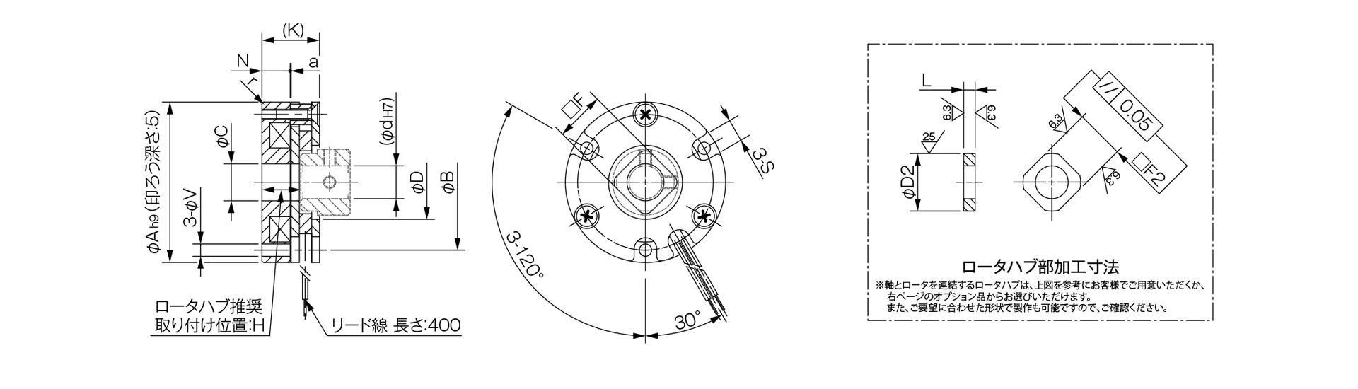
Unit [mm]
| Model | Size | Radial Dimensions | Axial Dimensions | Rotor Hub Machining Dimensions | |||||||||||||
|---|---|---|---|---|---|---|---|---|---|---|---|---|---|---|---|---|---|
| A | r | B | C | D | d max. | □F | S | V | H | K | N | a | L | D2 | □F2 | ||
| BXR-015-10LE | 015 | 26 | R0.5 | 22 | 7 | 12 | 6 | 8 | 4.3 | 2.3 | 9.5–10.0 | 14.0 | 7.0 | 0.1 | 4 or higher | 100⁻⁰.¹ | 80⁻⁰.⁰⁷ |
| BXR-020-10LE | 020 | 32 | R0.5 | 28 | 9 | 16 | 8 | 12 | 5.0 | 2.3 | 9.5–10.0 | 14.0 | 7.0 | 0.1 | 4 or higher | 140^(-0.1) | 120⁻⁰.⁰⁷ |
| BXR-025-10LE | 025 | 39 | R0.5 | 33 | 9 | 18 | 8 | 12 | 5.5 | 3.0 | 9.5–10.0 | 14.0 | 7.0 | 0.1 | 4 or higher | 140^(-0.1) | 120⁻⁰.⁰⁷ |
| BXR-035-10LE | 035 | 48 | R0.5 | 42 | 15 | 28 | 14 | 19 | 5.5 | 3.0 | 9.5–10.0 | 14.0 | 7.0 | 0.1 | 4 or higher | 230⁻⁰.¹ | 190⁻⁰.⁰⁷ |
| BXR-040-10LE | 040 | 56 | R0.5 | 50 | 15 | 27 | 14 | 19 | 6.5 | 3.4 | 9.9–10.4 | 14.5 | 7.4 | 0.1 | 4 or higher | 230 - 0.1 | 190⁻⁰.⁰⁷ |
| BXR-050-10LE | 050 | 71 | R0.5 | 65 | 22 | 37 | 20 | 25 | 8.0 | 4.4 | 14.0–14.4 | 19.0 | 10.5 | 0.1 | 4.5 or higher | 310⁻⁰.¹ | 250⁻⁰.⁰⁷ |
[Controller Specifications]
| Model | BEM-24ESN7-120N |
|---|---|
| Input Voltage | 24 VDC ±10% smoothed power supply |
| Output Voltage | Inrush: DC 24 V (0.2 s); Steady-state: DC 7 V (±10%)・PWM control *Output voltage is cut off when input voltage is 21 V DC or lower |
| Maximum output current | 1.0 A DC (ambient temperature 20°C) / 0.8 A DC (ambient temperature 60°C) |
| Rated duration | Continuous |
| Insulation resistance | 100 MΩ (between input/output and case) at 500 V DC |
| Dielectric strength | AC 1000 V, 50/60 Hz, 1 min (between input/output and case) |
| Ambient Environment | -20 to 60°C, 5 to 95% RH; no condensation or freezing |
[Controller Unit Dimensions]
[Controller Unit Structure]
[Timeline]