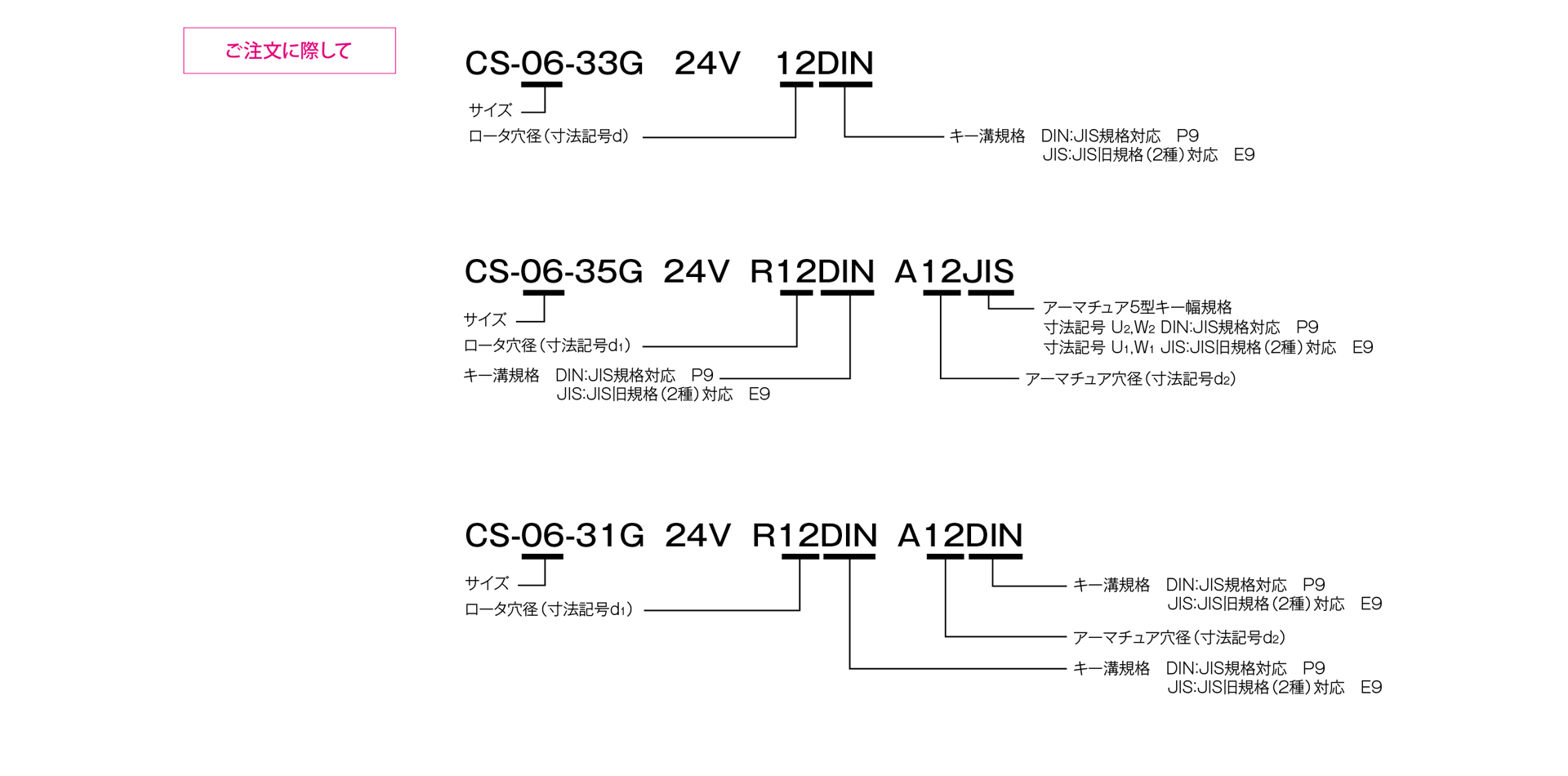
CS Model

This is a standard-size lineup of electromagnetically operated clutches that activate when an electric current is applied to the coil. Featuring a bearing-mounted design that allows for installation without worrying about alignment or centering, the series offers three types of armature assemblies with different mounting configurations, enabling you to select the one that best suits your installation requirements.
[Specifications]
| Model | Size | Dynamic friction torque Td [N·m] | Static friction torque Ts [N·m] | Coil (at 20°C) | Temperature Rating | Lead wire | Maximum rotational speed [min⁻¹] | Rotating part moment of inertia J | Total work until air gap readjustment ET [J] | Armature suction time ta [s] | Torque rise time tp [s] | Torque decay time td [s] | Mass [kg] | |||||
|---|---|---|---|---|---|---|---|---|---|---|---|---|---|---|---|---|---|---|
| Voltage [V] | Power [W] | Current [A] | Resistance [Ω] | UL Style | Size | Rotor [kg·m²] | Armature [kg·m²] | |||||||||||
| CS-06-33G | 06 | 5 | 5.5 | DC24 | 11 | 0.46 | 52 | B | UL3398 | AWG 22 | 3000 | 7.35×10⁻⁵ | 4.23×10⁻⁵ | 36×10⁶ | 0.020 | 0.041 | 0.020 | 0.50 |
| CS-06-35G | 06 | 5 | 5.5 | DC24 | 11 | 0.46 | 52 | B | UL3398 | AWG 22 | 3000 | 7.35×10⁻⁵ | 1.05×10⁻⁴ | 36×10⁶ | 0.020 | 0.041 | 0.020 | 0.70 |
| CS-06-31G | 06 | 5 | 5.5 | DC24 | 11 | 0.46 | 52 | B | UL3398 | AWG 22 | 3000 | 7.35×10⁻⁵ | 6.03×10⁻⁵ | 36×10⁶ | 0.020 | 0.041 | 0.020 | 0.54 |
| CS-08-33G | 08 | 10 | 11 | DC24 | 15 | 0.63 | 38 | B | UL3398 | AWG 18 | 3000 | 2.24×10⁻⁴ | 1.18×10⁻⁴ | 60×10⁶ | 0.023 | 0.051 | 0.030 | 0.87 |
| CS-08-35G | 08 | 10 | 11 | DC24 | 15 | 0.63 | 38 | B | UL3398 | AWG 18 | 3000 | 2.24×10⁻⁴ | 3.00×10⁻⁴ | 60×10⁶ | 0.023 | 0.051 | 0.030 | 1.23 |
| CS-08-31G | 08 | 10 | 11 | DC24 | 15 | 0.63 | 38 | B | UL3398 | AWG 18 | 3000 | 2.24×10⁻⁴ | 1.71×10⁻⁴ | 60×10⁶ | 0.023 | 0.051 | 0.030 | 0.95 |
| CS-10-33G | 10 | 20 | 22 | DC24 | 20 | 0.83 | 29 | B | UL3398 | AWG 18 | 3000 | 6.78×10⁻⁴ | 4.78×10⁻⁴ | 130×10⁶ | 0.025 | 0.063 | 0.050 | 1.57 |
| CS-10-35G | 10 | 20 | 22 | 24 V DC | 20 | 0.83 | 29 | B | UL3398 | AWG 18 | 3000 | 6.78×10⁻⁴ | 9.45×10⁻⁴ | 130×10⁶ | 0.025 | 0.063 | 0.050 | 2.18 |
| CS-10-31G | 10 | 20 | 22 | DC24 | 20 | 0.83 | 29 | B | UL3398 | AWG 18 | 3000 | 6.78×10⁻⁴ | 6.63×10⁻⁴ | 130×10⁶ | 0.025 | 0.063 | 0.050 | 1.73 |
| CS-12-33G | 12 | 40 | 45 | DC24 | 25 | 1.04 | 23 | B | UL3398 | AWG 18 | 2000 | 2.14×10⁻³ | 1.31×10⁻³ | 250×10⁶ | 0.040 | 0.115 | 0.065 | 2.89 |
| CS-12-35G | 12 | 40 | 45 | 24 V DC | 25 | 1.04 | 23 | B | UL3398 | AWG 18 | 2000 | 2.14×10⁻³ | 2.75×10⁻³ | 250×10⁶ | 0.040 | 0.115 | 0.065 | 3.93 |
| CS-12-31G | 12 | 40 | 45 | DC24 | 25 | 1.04 | 23 | B | UL3398 | AWG 18 | 2000 | 2.14×10⁻³ | 1.81×10⁻³ | 250×10⁶ | 0.040 | 0.115 | 0.065 | 3.18 |
| CS-16-33G | 16 | 80 | 90 | 24 V DC | 35 | 1.46 | 16 | B | UL3398 | AWG 18 | 2000 | 6.30×10⁻³ | 4.80×10⁻³ | 470×10⁶ | 0.050 | 0.160 | 0.085 | 5.3 |
| CS-16-35G | 16 | 80 | 90 | 24 V DC | 35 | 1.46 | 16 | B | UL3398 | AWG 18 | 2000 | 6.30×10⁻³ | 9.05×10⁻³ | 470×10⁶ | 0.050 | 0.160 | 0.085 | 7.1 |
| CS-16-31G | 16 | 80 | 90 | 24 V DC | 35 | 1.46 | 16 | B | UL3398 | AWG 18 | 2000 | 6.30×10⁻³ | 6.35×10⁻³ | 470×10⁶ | 0.050 | 0.160 | 0.085 | 5.6 |
| CS-20-33G | 20 | 160 | 175 | DC24 | 45 | 1.88 | 13 | B | UL3398 | AWG 16 | 1500 | 1.93×10⁻² | 1.37×10⁻² | 10×10⁸ | 0.090 | 0.250 | 0.130 | 9.8 |
| CS-25-33G | 25 | 320 | 350 | DC24 | 72 | 3.00 | 8 | B | UL3398 | AWG 16 | 1500 | 4.48×10⁻² | 3.58×10⁻² | 20×10⁸ | 0.115 | 0.335 | 0.210 | 17.5 |
- The dynamic friction torque Td is the value at a relative speed of 100 min⁻¹. Additionally, depending on the initial torque characteristics, a break-in period may be required.
- The moment of inertia and mass of the rotating section are based on the maximum bore diameter.
[Dimensions] For direct installation
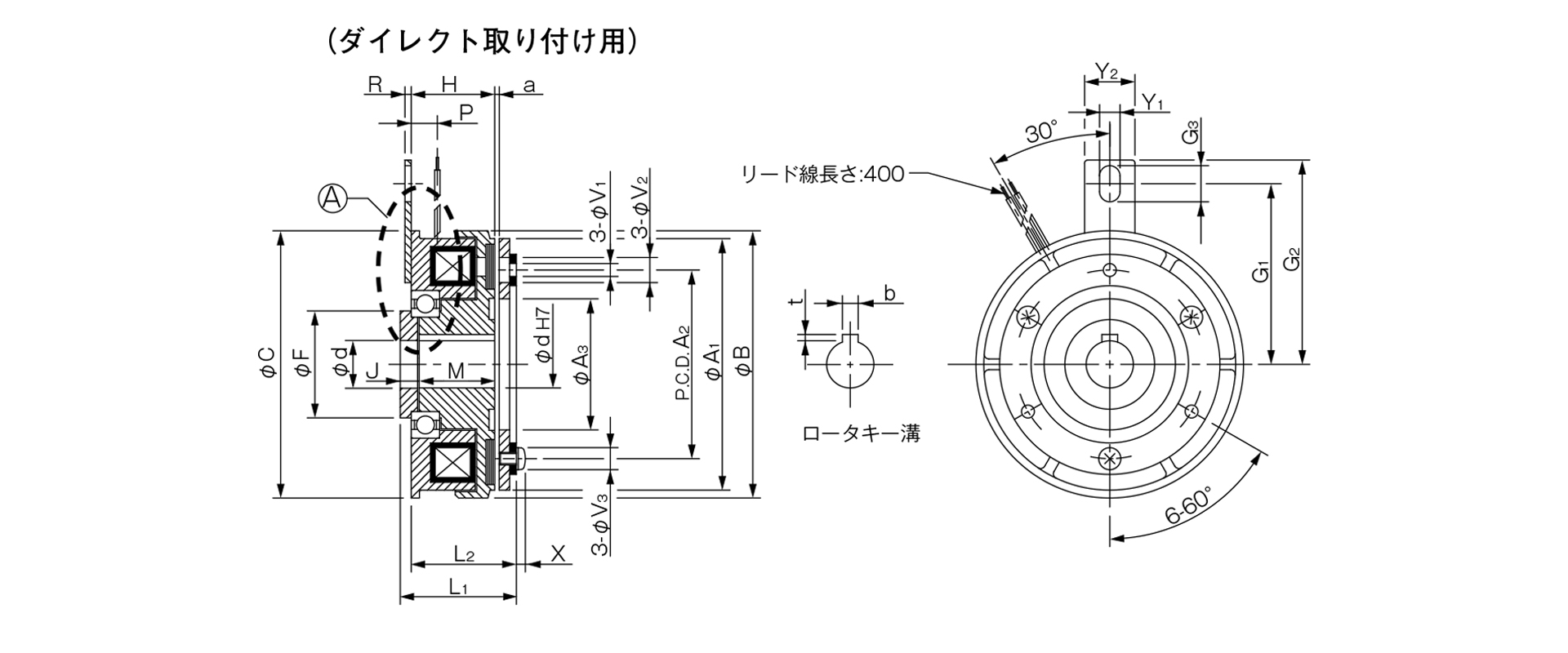
Unit [mm]
| Size | Radial dimensions | Axial dimensions | |||||||||||||||||||||
|---|---|---|---|---|---|---|---|---|---|---|---|---|---|---|---|---|---|---|---|---|---|---|---|
| A1 | A2 | A3 | B | C | F | G1 | G2 | G3 | V1 | V2 | V3 | Y1 | Y2 | H | L1 | L2 | M | J | P | R | X | a | |
| 06 | 63 | 46 | 34.5 | 67.5 | 67.5 | 24 | 42.5 | 50 | 9.5 | 3–3.1 | 3–6.3 | 3–5.5 | 4.5 | 14 | 24 | 31 | 28 | 22 | 5 | 7.3 | 2 | 2.5 | 0.2–±0.05 |
| 08 | 80 | 60 | 41.7 | 85 | 85 | 34 | 57.5 | 65 | 11.5 | 3-4.1 | 3-8 | 3-7 | 6.5 | 16 | 26.5 | 34.5 | 31 | 24 | 6 | 8.3 | 2 | 2.85 | 0.2–±0.05 |
| 10 | 100 | 76 | 51.5 | 106 | 106 | 40 | 62.5 | 70 | 11.5 | 3-5.1 | 3-11 | 3-9 | 6.5 | 16 | 30 | 39.6 | 36.1 | 27 | 6.5 | 9 | 2 | 3.3 | 0.2–±0.05 |
| 12 | 125 | 95 | 61.5 | 133 | 133 | 45 | 77.5 | 85 | 11.5 | 3-6.1 | 3-12 | 3-11 | 6.5 | 16 | 33.5 | 44.5 | 40.5 | 30 | 7.5 | 9.3 | 2 | 3.3 | 0.3 + 0.05 - 0.1 |
| 16 | 160 | 120 | 79.5 | 169 | 169 | 58 | 100 | 112 | 18.5 | 3–8.2 | 3-15 | 3-14 | 8.5 | 25 | 37.5 | 50.5 | 46.5 | 34 | 7.5 | 11.7 | 3.2 | 3.5 | 0.3 + 0.05 - 0.1 |
| 20 | 200 | 158 | 99.5 | 212.5 | 212 | 75 | 125 | 138 | 18.5 | 3–10.2 | 3-18 | 3–16.2 | 8.5 | 25 | 44 | 60.4 | 55.4 | 40 | 9 | 13.4 | 3 | 4.9 | 0.50–0.2 |
| 25 | 250 | 210 | 124.5 | 264 | 250 | 100 | 155 | 173 | 24 | 4-12.2 | 4-22 | 4-20 | 12 | 30 | 53 | 68.9 | 65.9 | 47 | 9 | 18 | 6 | 5.5 | 0.50–0.2 |
Unit [mm]
| Size | Shaft Bore Dimensions | ||||
|---|---|---|---|---|---|
| dH7 | Compliant with JIS standards | Compatible with Old JIS Standards | |||
| dH7 | bP9 | t | bE9 | t | |
| 6 | 12 | 4–0.012–0.042 | 1.5 + 0.50 | 4 + 0.050 + 0.020 | 1.5 + 0.50 |
| 8 | 15 | 5–0.012–0.042 | 2 + 0.50 | 5 + 0.050 + 0.020 | 2 + 0.50 |
| 10 | 20 | 6–0.012–0.042 | 2.5 + 0.50 | 5 + 0.050 + 0.020 | 2 + 0.50 |
| 12 | 25 | 8–0.015–0.051 | 3 + 0.50 | 7 + 0.061 + 0.025 | 3 + 0.50 |
| 16 | 30 | 8 - 0.015 - 0.051 | 3 + 0.50 | 7 + 0.061 + 0.025 | 3 + 0.50 |
| 20 | 40 | 12–0.018–0.061 | 3 + 0.50 | 10 + 0.061 + 0.025 | 3.5 + 0.50 |
| 25 | 50 | 14–0.018–0.061 | 3.5 + 0.50 | 12 + 0.075 + 0.032 | 3.5 + 0.50 |
- For information regarding installation methods and other details, please refer to the design specifications.
[Dimensions] For through-shafts
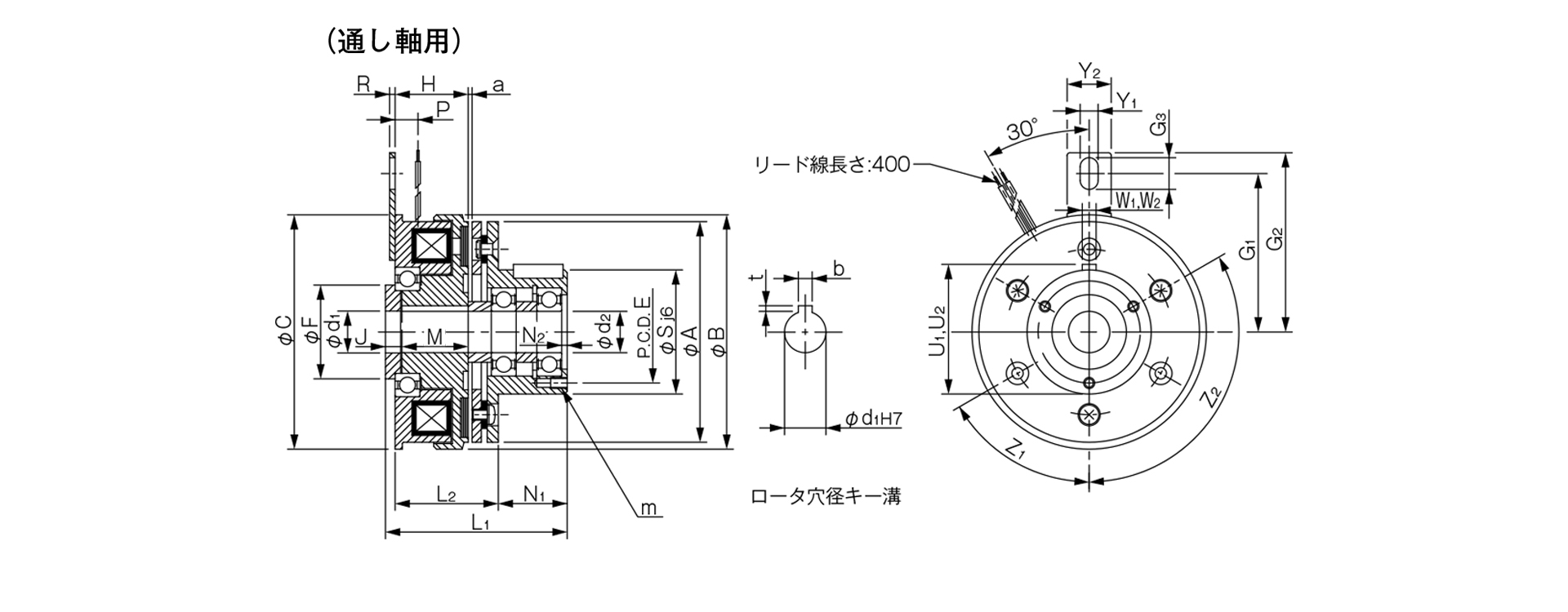
Unit [mm]
| Size | Radial dimensions | Axial dimensions | ||||||||||||||||||||||||||
|---|---|---|---|---|---|---|---|---|---|---|---|---|---|---|---|---|---|---|---|---|---|---|---|---|---|---|---|---|
| A | B | C | E | F | G1 | G2 | G3 | S | Y1 | Y2 | Z1 | Z2 | H | L1 | L2 | M | J | N1 | N2 | P | R | U1 | W1 | U2 | W2 | a | m | |
| 06 | 63 | 67.5 | 67.5 | 33 | 24 | 42.5 | 50 | 9.5 | 38 | 4.5 | 14 | 3–120° | 0° | 24 | 54.5 | 31.5 | 22 | 5 | 20 | 2 | 7.3 | 2 | 39.5 | 4 | 39.5 | 4 | 0.2–±0.05 | 3-M4×0.7, depth 4 |
| 08 | 80 | 85 | 85 | 37 | 34 | 57.5 | 65 | 11.5 | 45 | 6.5 | 16 | 3–120° | 0° | 26.5 | 63.5 | 35 | 24 | 6 | 25 | 2 | 8.3 | 2 | 47 | 5 | 47 | 5 | 0.2–±0.05 | 3-M4×0.7, depth 6 |
| 10 | 100 | 106 | 106 | 47 | 40 | 62.5 | 70 | 11.5 | 55 | 6.5 | 16 | 4–90° | 45° | 30 | 74.6 | 41.1 | 27 | 6.5 | 30 | 3 | 9 | 2 | 57 | 5 | 57.5 | 6 | 0.2–±0.05 | 4-M4×0.7, depth 8 |
| 12 | 125 | 133 | 133 | 52 | 45 | 77.5 | 85 | 11.5 | 64 | 6.5 | 16 | 4–90° | 45° | 33.5 | 90.5 | 46.5 | 30 | 7.5 | 40 | 2.2 | 9.3 | 2 | 67 | 7 | 67 | 8 | 0.3 + 0.05 – 0.1 | 4-M4×0.7, depth 8 |
| 16 | 160 | 169 | 169 | 62 | 58 | 100 | 112 | 18.5 | 75 | 8.5 | 25 | 6–60° | 30° | 37.5 | 107.5 | 53.5 | 34 | 7.5 | 50 | 3 | 11.7 | 3.2 | 78 | 7 | 78 | 8 | 0.3 + 0.05 – 0.1 | 6-M5×0.8, depth 8 |
Unit [mm]
| Size | Shaft hole dimensions | |||||
|---|---|---|---|---|---|---|
| d1 H7 | d2 | Compliant with JIS standards | Compatible with old JIS standards | |||
| d1H7 | bP9 | t | bE9 | t | ||
| 6 | 12 | 12 | 4–0.012–0.042 | 1.5 + 0.50 | 4 + 0.050 + 0.020 | 1.5 + 0.50 |
| 8 | 15 | 15 | 5–0.012–0.042 | 2 + 0.50 | 5 + 0.050 + 0.020 | 2 + 0.50 |
| 10 | 20 | 20 | 6–0.012–0.042 | 2.5 + 0.50 | 5 + 0.050 + 0.020 | 2 + 0.50 |
| 12 | 25 | 25 | 8–0.015–0.051 | 3 + 0.50 | 7 + 0.061 + 0.025 | 3 + 0.50 |
| 16 | 30 | 30 | 8–0.015–0.051 | 3 + 0.50 | 7 + 0.061 + 0.025 | 3 + 0.50 |
- For information regarding installation methods, please refer to the design specifications.
[Dimensions] For butt-joint shafts
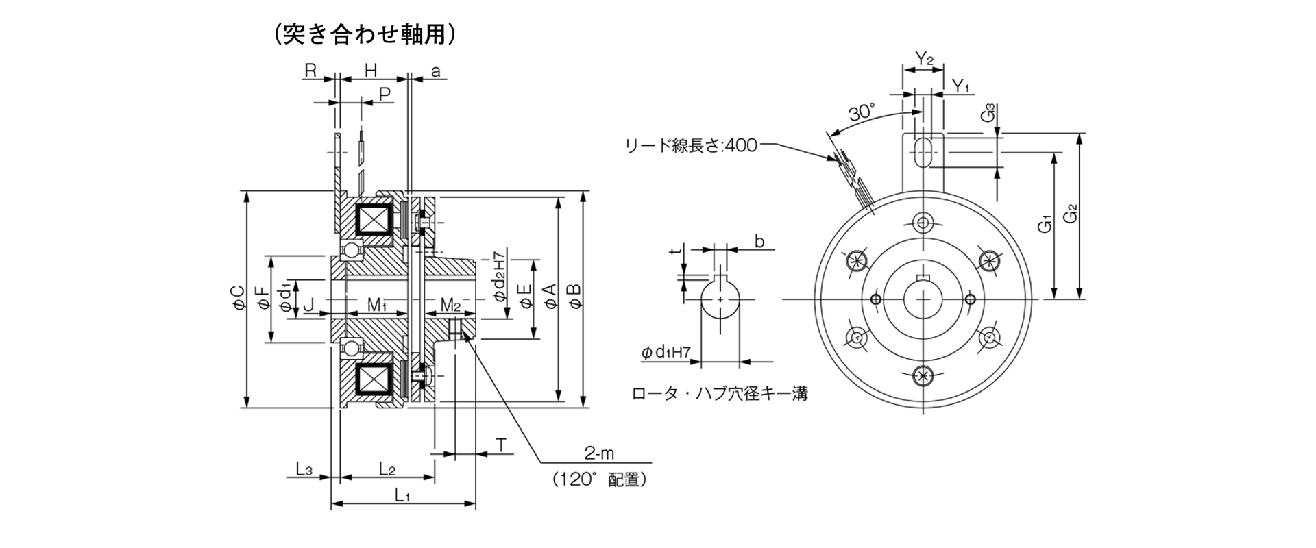
Unit [mm]
| Size | Radial dimensions | Axial dimensions | ||||||||||||||||||||
|---|---|---|---|---|---|---|---|---|---|---|---|---|---|---|---|---|---|---|---|---|---|---|
| A | B | C | E | F | G1 | G2 | G3 | Y1 | Y2 | m | H | L1 | L2 | L3 | M1 | M2 | J | P | R | T | a | |
| 06 | 63 | 67.5 | 67.5 | 26 | 24 | 42.5 | 50 | 9.5 | 4.5 | 14 | M4 | 24 | 46 | 31.5 | 3 | 22 | 15 | 5 | 7.3 | 2 | 6 | 0.2–±0.05 |
| 08 | 80 | 85 | 85 | 31 | 34 | 57.5 | 65 | 11.5 | 6.5 | 16 | M5 | 26.5 | 54.5 | 35 | 3.5 | 24 | 20 | 6 | 8.3 | 2 | 8 | 0.2–±0.05 |
| 10 | 100 | 106 | 106 | 41 | 40 | 62.5 | 70 | 11.5 | 6.5 | 16 | M5 | 30 | 64.6 | 41.1 | 3.5 | 27 | 25 | 6.5 | 9 | 2 | 10 | 0.2–±0.05 |
| 12 | 125 | 133 | 133 | 49 | 45 | 77.5 | 85 | 11.5 | 6.5 | 16 | M6 | 33.5 | 74.5 | 46.5 | 4 | 30 | 30 | 7.5 | 9.3 | 2 | 12 | 0.3 + 0.05 - 0.1 |
| 16 | 160 | 169 | 169 | 65 | 58 | 100 | 112 | 18.5 | 8.5 | 25 | M8 | 37.5 | 88.5 | 53.5 | 4 | 34 | 38 | 7.5 | 11.7 | 3.2 | 15 | 0.3 + 0.05 – 0.1 |
Unit [mm]
| Size | Shaft bore dimensions | |||||
|---|---|---|---|---|---|---|
| d1H7 | d2H7 | Compliant with JIS standards | Compatible with old JIS standards | |||
| d1H7 | bP9 | t | bE9 | t | ||
| 6 | 12 | 12 | 4–0.012–0.042 | 1.5 + 0.50 | 4 + 0.050 + 0.020 | 1.5 + 0.50 |
| 8 | 15 | 15 | 5–0.012–0.042 | 2 + 0.50 | 5 + 0.050 + 0.020 | 2 + 0.50 |
| 10 | 20 | 20 | 6–0.012–0.042 | 2.5 + 0.50 | 5 + 0.050 + 0.020 | 2 + 0.50 |
| 12 | 25 | 25 | 8–0.015–0.051 | 3 + 0.50 | 7 + 0.061 + 0.025 | 3 + 0.50 |
| 16 | 30 | 30 | 8–0.015–0.051 | 3 + 0.50 | 7 + 0.061 + 0.025 | 3 + 0.50 |
- For information regarding installation methods and other details, please refer to the design specifications.