CYT Model
![三木プーリの励磁作動形クラッチ CYT[33B]タイプ フランジ取り付け形製品画像(壁面取り付け用・電磁クラッチ・産業用駆動制御)](/media/cb_cl_clf_cyt_0l.jpg)
This is a compact, custom-designed electromagnetically operated clutch that activates when an electric current is applied to the coil. It features a bearing-mounted design that allows for installation without worrying about alignment or centering. Three types of armature assemblies with different mounting configurations are available, so you can select the one that best suits your installation requirements.
[Specifications]
| Model | Size | Dynamic friction torque Td [N·m] | Coil (at 20°C) | Temperature Rating | Lead Wires | Maximum rotational speed [min⁻¹] | Rotating mass moment of inertia J | Allowable connected work Eeaℓ [J] | Total work ET [J] | Armature attraction time ta [s] | Torque rise time tp [s] | Torque decay time td [s] | Mass [kg] | |||||
|---|---|---|---|---|---|---|---|---|---|---|---|---|---|---|---|---|---|---|
| Voltage [V] | Power [W] | Current [A] | Resistance [Ω] | UL Style | Size | Armature [kg·m²] | Rotor [kg·m²] | |||||||||||
| CYT-025-33B | 025 | 0.4 | DC24 | 4.5 | 0.188 | 128 | B | UL3398 | AWG 26 | 3600 | 1.00×10⁻⁶ | 1.43×10⁻⁶ | 800 | 1.0×10⁶ | 0.014 | 0.028 | 0.030 | 0.07 |
| CYT-03-33B | 03 | 0.5 | DC24 | 5.5 | 0.23 | 105 | B | UL3398 | AWG 26 | 3600 | 1.30×10⁻⁶ | 1.85×10⁻⁶ | 900 | 1.5×10⁶ | 0.015 | 0.030 | 0.040 | 0.13 |
| CYT-04-33B | 04 | 1.0 | DC24 | 5.9 | 0.25 | 98 | B | UL3398 | AWG 26 | 3600 | 5.15×10⁻⁶ | 1.00×10⁻⁵ | 1900 | 2.0×10⁶ | 0.030 | 0.040 | 0.040 | 0.26 |
- The dynamic friction torque Td is the value at a relative speed of 100 min⁻¹. Additionally, depending on the initial torque characteristics, a break-in period may be required.
- Keep fluctuations in the supply voltage within ±10% of the coil voltage. Also, ensure that the duty cycle does not exceed 50%.
- The moment of inertia and mass of the rotating section are based on the maximum bore diameter.
[Dimensions] Bearing Mounting Type
CYT-025-33B (top row) CYT-□-33B (bottom row)
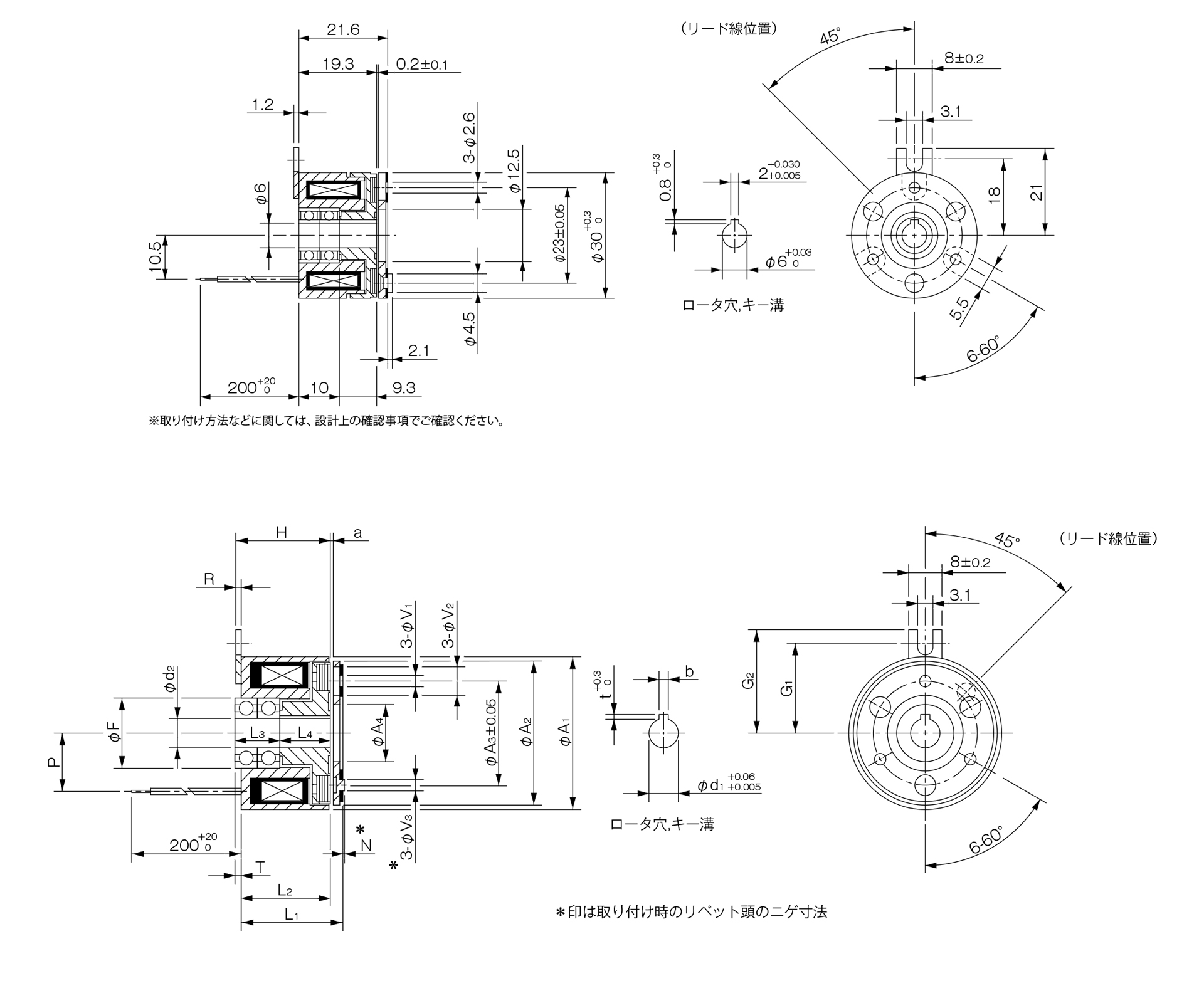
| Size | Nominal Diameter | Radial dimensions | Axial dimensions | Bore dimensions | |||||||||||||||||||||
|---|---|---|---|---|---|---|---|---|---|---|---|---|---|---|---|---|---|---|---|---|---|---|---|---|---|
| Nominal diameter | A1 | A2 | A3 | A4 | F | V1 | V2 | V3 | G1 | G2 | H | R | L1 | L2 | L3 | L4 | P | N | T | a | d2 | d1 | b | t | |
| 03 | 6 | 34 | 32 | 23 | 12.5 | 15 | 3–2.6 | 3–5.5 | 3-6 | 20 | 23 | 21 | 1.2 | 22.2 | 19.8 | 10 | 11.3 | 13 | 3 | 1.5 | 0.2 ± 0.05 | 6 | 6 | 2 + 0.030 – 0.005 | 0.8 + 0.30 |
| 8 | 34 | 32 | 23 | 12.5 | 16 | 3–2.6 | 3–5.5 | 3-6 | 20 | 23 | 21 | 1.2 | 22.2 | 19.8 | 10 | 11.3 | 13 | 3 | 1.5 | 0.2 ± 0.05 | 8 | 8 | 2 + 0.030 – 0.005 | 0.8 + 0.30 | |
| 04 | 8 | 45 | 42 | 30 | 18.5 | 19 | 3-3.1 | 3-6 | 3-6 | 25 | 28 | 25.3 | 1.2 | 26.8 | 24.1 | 12 | 13 | 17.5 | 3.5 | 0.9 | 0.2 + 0.05 - 0.1 | 8 | 8 | 2 + 0.030 – 0.005 | 0.8 + 0.30 |
| 10 | 45 | 42 | 30 | 18.5 | 19 | 3-3.1 | 3-6 | 3-6 | 25 | 28 | 25.3 | 1.2 | 26.8 | 24.1 | 14 | 11 | 17.5 | 3.5 | 0.9 | 0.2 + 0.05 - 0.1 | 10 | 10 | 3 + 0.025 – 0 | 1.2 + 0.30 | |
- The dimensional symbols N and V3 indicate the clearance dimensions of the rivet head during installation.
- For information regarding installation methods and other details, please refer to the design specifications.